Table des Matières
Publicité
Les langues disponibles
Les langues disponibles
Liens rapides
LOV TO ELECTRIC S.P. .
24020 GORLE (BERG MO) IT LI
VI DON E. M ZZ , 12
TEL. 035 4282111
F X (Nazionale): 035 4282200
F X (International): +39 035 4282400
L
E
E-mail info@
ovato
lectric.com
L
E
Web
www.
ovato
lectric.com
GB
DMG800
D
vailable in German at www.LovatoElectric.com/I272D.pdf
PL
vailable in Polish at www.LovatoElectric.com/I272PL.pdf
W RNING!
- Carefully read the manual before the installation or use.
- This equipment is to be installed by qualified personnel, complying with current standards, to avoid damages or safety hazards.
- Before any maintenance operation on the device, remove all the voltages from supply and measuring inputs and short-circuit the CT input terminals.
- The manufacturer cannot be held responsible for electrical safety in case of improper use of the equipment.
- Products illustrated herein are subject to alteration and changes without prior notice. Technical data and descriptions in the documentation are accurate, to
the best of our knowledge, but no liabilities for errors, omissions or contingencies arising therefrom are accepted.
-
circuit breaker must be included in the electrical installation of the building. It must be installed close by the equipment and within easy reach of the
operator. It must be marked as the disconnecting device of the equipment: IEC /EN 61010-1 § 6.11.2.
- Clean the instrument with a soft dry cloth; do not use abrasives, liquid detergents or solvents.
INDEX
Introduction . . . . . . . . . . . . . . . . . . . . . . . . . . . . . . . . . . . . . . . . . . . . . . . . . . . . . . . . . . . . . . . . . . . . . . . . . . . . . . . . . . . . . . . . . . . . . . . . . . . . . . . . . . . . . . . . .
Description . . . . . . . . . . . . . . . . . . . . . . . . . . . . . . . . . . . . . . . . . . . . . . . . . . . . . . . . . . . . . . . . . . . . . . . . . . . . . . . . . . . . . . . . . . . . . . . . . . . . . . . . . . . . . . . . . .
Keyboard functions . . . . . . . . . . . . . . . . . . . . . . . . . . . . . . . . . . . . . . . . . . . . . . . . . . . . . . . . . . . . . . . . . . . . . . . . . . . . . . . . . . . . . . . . . . . . . . . . . . . . . . . . . . .
Measurement viewing . . . . . . . . . . . . . . . . . . . . . . . . . . . . . . . . . . . . . . . . . . . . . . . . . . . . . . . . . . . . . . . . . . . . . . . . . . . . . . . . . . . . . . . . . . . . . . . . . . . . . . . . .
Table of display pages . . . . . . . . . . . . . . . . . . . . . . . . . . . . . . . . . . . . . . . . . . . . . . . . . . . . . . . . . . . . . . . . . . . . . . . . . . . . . . . . . . . . . . . . . . . . . . . . . . . . . . . . .
Display page navigation . . . . . . . . . . . . . . . . . . . . . . . . . . . . . . . . . . . . . . . . . . . . . . . . . . . . . . . . . . . . . . . . . . . . . . . . . . . . . . . . . . . . . . . . . . . . . . . . . . . . . . . .
Harmonic analysis page . . . . . . . . . . . . . . . . . . . . . . . . . . . . . . . . . . . . . . . . . . . . . . . . . . . . . . . . . . . . . . . . . . . . . . . . . . . . . . . . . . . . . . . . . . . . . . . . . . . . . . . .
Waveform page . . . . . . . . . . . . . . . . . . . . . . . . . . . . . . . . . . . . . . . . . . . . . . . . . . . . . . . . . . . . . . . . . . . . . . . . . . . . . . . . . . . . . . . . . . . . . . . . . . . . . . . . . . . . . .
Energy meters page . . . . . . . . . . . . . . . . . . . . . . . . . . . . . . . . . . . . . . . . . . . . . . . . . . . . . . . . . . . . . . . . . . . . . . . . . . . . . . . . . . . . . . . . . . . . . . . . . . . . . . . . . . .
Hour counters page . . . . . . . . . . . . . . . . . . . . . . . . . . . . . . . . . . . . . . . . . . . . . . . . . . . . . . . . . . . . . . . . . . . . . . . . . . . . . . . . . . . . . . . . . . . . . . . . . . . . . . . . . . .
Trend graph page . . . . . . . . . . . . . . . . . . . . . . . . . . . . . . . . . . . . . . . . . . . . . . . . . . . . . . . . . . . . . . . . . . . . . . . . . . . . . . . . . . . . . . . . . . . . . . . . . . . . . . . . . . . . .
Counters page . . . . . . . . . . . . . . . . . . . . . . . . . . . . . . . . . . . . . . . . . . . . . . . . . . . . . . . . . . . . . . . . . . . . . . . . . . . . . . . . . . . . . . . . . . . . . . . . . . . . . . . . . . . . . . .
User pages . . . . . . . . . . . . . . . . . . . . . . . . . . . . . . . . . . . . . . . . . . . . . . . . . . . . . . . . . . . . . . . . . . . . . . . . . . . . . . . . . . . . . . . . . . . . . . . . . . . . . . . . . . . . . . . . . .
Main menu . . . . . . . . . . . . . . . . . . . . . . . . . . . . . . . . . . . . . . . . . . . . . . . . . . . . . . . . . . . . . . . . . . . . . . . . . . . . . . . . . . . . . . . . . . . . . . . . . . . . . . . . . . . . . . . . . .
Password access . . . . . . . . . . . . . . . . . . . . . . . . . . . . . . . . . . . . . . . . . . . . . . . . . . . . . . . . . . . . . . . . . . . . . . . . . . . . . . . . . . . . . . . . . . . . . . . . . . . . . . . . . . . . .
Settings lock. . . . . . . . . . . . . . . . . . . . . . . . . . . . . . . . . . . . . . . . . . . . . . . . . . . . . . . . . . . . . . . . . . . . . . . . . . . . . . . . . . . . . . . . . . . . . . . . . . . . . . . . . . . . . . . . .
Expandability . . . . . . . . . . . . . . . . . . . . . . . . . . . . . . . . . . . . . . . . . . . . . . . . . . . . . . . . . . . . . . . . . . . . . . . . . . . . . . . . . . . . . . . . . . . . . . . . . . . . . . . . . . . . . . . .
dditional resources. . . . . . . . . . . . . . . . . . . . . . . . . . . . . . . . . . . . . . . . . . . . . . . . . . . . . . . . . . . . . . . . . . . . . . . . . . . . . . . . . . . . . . . . . . . . . . . . . . . . . . . . . . .
Communication channels . . . . . . . . . . . . . . . . . . . . . . . . . . . . . . . . . . . . . . . . . . . . . . . . . . . . . . . . . . . . . . . . . . . . . . . . . . . . . . . . . . . . . . . . . . . . . . . . . . . . . . .
Inputs, outputs, internal variables, counters . . . . . . . . . . . . . . . . . . . . . . . . . . . . . . . . . . . . . . . . . . . . . . . . . . . . . . . . . . . . . . . . . . . . . . . . . . . . . . . . . . . . . . . .
Limit thresholds . . . . . . . . . . . . . . . . . . . . . . . . . . . . . . . . . . . . . . . . . . . . . . . . . . . . . . . . . . . . . . . . . . . . . . . . . . . . . . . . . . . . . . . . . . . . . . . . . . . . . . . . . . . . . .
Boolean logic . . . . . . . . . . . . . . . . . . . . . . . . . . . . . . . . . . . . . . . . . . . . . . . . . . . . . . . . . . . . . . . . . . . . . . . . . . . . . . . . . . . . . . . . . . . . . . . . . . . . . . . . . . . . . . . .
Remote-controlled variables. . . . . . . . . . . . . . . . . . . . . . . . . . . . . . . . . . . . . . . . . . . . . . . . . . . . . . . . . . . . . . . . . . . . . . . . . . . . . . . . . . . . . . . . . . . . . . . . . . . . .
larms . . . . . . . . . . . . . . . . . . . . . . . . . . . . . . . . . . . . . . . . . . . . . . . . . . . . . . . . . . . . . . . . . . . . . . . . . . . . . . . . . . . . . . . . . . . . . . . . . . . . . . . . . . . . . . . . . . . . .
Tariffs . . . . . . . . . . . . . . . . . . . . . . . . . . . . . . . . . . . . . . . . . . . . . . . . . . . . . . . . . . . . . . . . . . . . . . . . . . . . . . . . . . . . . . . . . . . . . . . . . . . . . . . . . . . . . . . . . . . . . .
Data logger function. . . . . . . . . . . . . . . . . . . . . . . . . . . . . . . . . . . . . . . . . . . . . . . . . . . . . . . . . . . . . . . . . . . . . . . . . . . . . . . . . . . . . . . . . . . . . . . . . . . . . . . . . . .
Setting of parameters (setup) . . . . . . . . . . . . . . . . . . . . . . . . . . . . . . . . . . . . . . . . . . . . . . . . . . . . . . . . . . . . . . . . . . . . . . . . . . . . . . . . . . . . . . . . . . . . . . . . . . .
Table of parameters . . . . . . . . . . . . . . . . . . . . . . . . . . . . . . . . . . . . . . . . . . . . . . . . . . . . . . . . . . . . . . . . . . . . . . . . . . . . . . . . . . . . . . . . . . . . . . . . . . . . . . . . . . .
Commands menu . . . . . . . . . . . . . . . . . . . . . . . . . . . . . . . . . . . . . . . . . . . . . . . . . . . . . . . . . . . . . . . . . . . . . . . . . . . . . . . . . . . . . . . . . . . . . . . . . . . . . . . . . . . . .
Wiring test . . . . . . . . . . . . . . . . . . . . . . . . . . . . . . . . . . . . . . . . . . . . . . . . . . . . . . . . . . . . . . . . . . . . . . . . . . . . . . . . . . . . . . . . . . . . . . . . . . . . . . . . . . . . . . . . . .
Terminal arrangement. . . . . . . . . . . . . . . . . . . . . . . . . . . . . . . . . . . . . . . . . . . . . . . . . . . . . . . . . . . . . . . . . . . . . . . . . . . . . . . . . . . . . . . . . . . . . . . . . . . . . . . . . .
Mechanical dimensions . . . . . . . . . . . . . . . . . . . . . . . . . . . . . . . . . . . . . . . . . . . . . . . . . . . . . . . . . . . . . . . . . . . . . . . . . . . . . . . . . . . . . . . . . . . . . . . . . . . . . . . .
Technical characteristics. . . . . . . . . . . . . . . . . . . . . . . . . . . . . . . . . . . . . . . . . . . . . . . . . . . . . . . . . . . . . . . . . . . . . . . . . . . . . . . . . . . . . . . . . . . . . . . . . . . . . . . .
Installation . . . . . . . . . . . . . . . . . . . . . . . . . . . . . . . . . . . . . . . . . . . . . . . . . . . . . . . . . . . . . . . . . . . . . . . . . . . . . . . . . . . . . . . . . . . . . . . . . . . . . . . . . . . . . . . . . .
Wiring diagrams. . . . . . . . . . . . . . . . . . . . . . . . . . . . . . . . . . . . . . . . . . . . . . . . . . . . . . . . . . . . . . . . . . . . . . . . . . . . . . . . . . . . . . . . . . . . . . . . . . . . . . . . . . . . . .
INTRODUCTION
The DMG800 multimeter has been designed to combine the maximum possible easiness of operation together with a wide choice of advanced functions. Thanks
to its flush-mount 96x96mm housing, the DMG800 joins the modern design of the front panel with the tool-less mounting of the device body and the expansion
capability of the rear panel, where it is possible to mount plug-in modules of EXP... series. The graphic LCD graphic display offers a user-friendly interface.
The rich variety of functions, makes the DMG series multimeters the ideal choice for a wide range of applications.
Digital multimeter
Instructions manual
CZ
vailable in Czech at www.LovatoElectric.com/I272CZ.pdf
RU
vailable in Russian at www.LovatoElectric.com/I272RU.pdf
G
B
Page
1
2
2
2
3
3
4
4
4
4
4
5
5
5
5
6
6
7
7
8
8
8
9
9
9
9
10
11
15
16
16
16
17
18
19
1
Publicité
Chapitres
Table des Matières

Manuels Connexes pour LOVATO ELECTRIC DMG800


Sommaire des Matières pour LOVATO ELECTRIC DMG800
-
Page 1: Table Des Matières
The DMG800 multimeter has been designed to combine the maximum possible easiness of operation together with a wide choice of advanced functions. Thanks to its flush-mount 96x96mm housing, the DMG800 joins the modern design of the front panel with the tool-less mounting of the device body and the expansion capability of the rear panel, where it is possible to mount plug-in modules of EXP…... -
Page 2: Description
DESCRIPTION – Flush-mount housing, 96x96mm – Graphic LCD display, 128x80 pixels, white backlight, 4 grey levels. – Keyboard with 4 keys for visualization and setting. – Easy and fast navigation. – Compatible with LV, MV, HV applications. – Texts for measures, setup and messages in 5 languages. -
Page 3: Table Of Display
T BLE OF DISPL Y P GES Selection with s and t Selection with N° P GE SUB P GES PH SE-TO-PH SE VOLT GES - V(L1-L2), V(L2-L3), V(L3-L1), V(LL)EQV PH SE-TO-NEUTR L VOLT GES - V(L1-N), V(L2-N), V(L3-N), V(L-N)EQV PH SE ND NEUTR L CURRENTS - I(L1), I(L2), I(L3), I(N) CTIVE POWER - P(L1), P(L2), P(L3), P(TOT) RE CTIVE POWER - Q(L1), Q(L2), Q(L3), Q(TOT) -
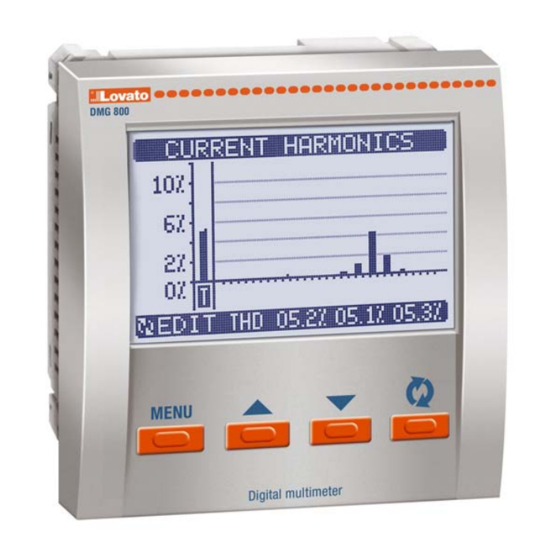
Page 4: Harmonic Analysis Page
1 - Numeric values of the selected order ENERGY METERS P GE – This page graphically views the waveform of the voltage and current signals read by the DMG800. – It is possible to see one phase at a time, selecting it with key. -
Page 5: Counters Page
– Each of these pages can view 4 measurements, freely chosen among the available readings of the DMG800. – The title of the page can be freely programmed by the user, allowing, for instance, indicating the part of the plant supervised by the multimeter. -
Page 6: Settings Lock
SETTINGS LOCK – On the DMG800 there are two DIP switches that are used to lock the access to parameter settings and / or to reset operations (commands menu). – This DIP switches are placed in a way that they become unaccessible once the sealable terminal cover is mounted. -
Page 7: Dditional Resources
– ctivating the Gateway function it is possible to use a DMG800 with both an Ethernet port and a RS485 port, that acts as a bridge over other DMGs equipped with RS-485 only, in order to achieve a more economic configuration (only one Ethernet port). -
Page 8: Inputs, Outputs, Internal Variables, Counters
INP2, INP3 and so on. – The DMG800 supports a maximum of 8 digital inputs and 8 outputs that will thus be numbered INP1…8 and OUT1…8. For every I/O, there is a dedicated setting menu that allows to specify functionality and properties. -
Page 9: Remote-Controlled Variables
T RIFFS – For the Energy billing, the DMG800 can manage 4 different tariffs in addition to the total and partial Energy meters. – The tariff selection is made by external digital inputs, and is thus conditioned by the use of an EXP expansion module provided with digital inputs. To select among the 4 tariffs, the two input functions T R- and T R-B must be used. -
Page 10: Setting Of Parameters (Setup)
– Data recorded by the DMG can be downloaded to the PC disk through a serial interface module. – For detailed information about the setting of datalogger function see the manual of the DMK-DMG data logger software. – Note: The memory module mandatory position is slot 1 of the DMG expansion bus (leftmost). P R METER SETTING (SET-UP) –... -
Page 11: Table Of Parameters
P R METER T BLE M01 - GENER L Default Range P01.01 CT primary 1-10000 P01.02 CT secondary P01.03 Rated voltage ut / 50-500000 P01.04 VT usage OFF-ON P01.05 VT primary 50-500000 P01.06 VT secondary 50-500 P01.07 Type of wiring L1-L2-L3-N L1-L2-L3-N L1-L2-L3... - Page 12 M05 - HOUR COUNTER Default Range P05.01 Hour meter counter enable OFF-ON P05.02 Partial hour counter enable OFF-ON- INPx- LIMx-BOOx P05.03 Channel number (x) P05.01 – If set to OFF the hour meter s are disabled and the hour meter page is not shown. P05.02 –...
- Page 13 M08 - LIMIT TRESHOLDS Default Range P08.n.01 Reference measure OFF- (measures) P08.n.02 Function Max - Min - Min+Max P08.n.03 Upper threshold -9999 - +9999 P08.n.04 Multiplier /100 - x10k P08.n.05 Delay 0.0 - 600.0 P08.n.06 Lower threshold -9999 - +9999 P08.n.07 Multiplier /100 - x10k P08.n.08 Delay...
- Page 14 M12 - BOOLE N LOGIC Default Range P12.n.01 Operand 1 OFF-LIMx-INPx-OUTx-REMx-BOOx P12.n.02 Channel number (x) 1 - 8 P12.n.03 Logic operator 1 - - - - - - - ND - OR - EXOR - ND NOT - OR NOT - EXOR NOT P12.n.04 Operand 2 OFF-LIMx-INPx-OUTx-REMx-BOOx P12.n.05 Channel number (x)
-
Page 15: Commands Menu
M16 - N LOG INPUTS Default Range P16.n.01 Input type 0..20m 4….20m 0…10V -5V…+5V PT100 P16.n.02 Start of scale value -9999 - +9999 P16.n.03 Multiplier /100 – x1k P16.n.04 Full scale value -9999 - +9999 P16.n.05 Multiplier /100 – x1k P16.n.06 Description (Text –... -
Page 16: Wiring Test
WIRING TEST – The wiring test allows to verify if the connection of the DMG device has been executed properly. – To be able to execute the test, the device must be connected to an active plant, with the following conditions: •... -
Page 17: Technical Characteristics
TECHNIC L CH R CTERISTICS uxiliary supply mbient conditions Rated voltage Us ∂ 100 - 440V Operating temperature -20...+60°C 110 - 250V Storage temperature -30...+80°C Operating voltage range 90 - 484V Relative humidity <80% (IEC/EN 60068-2-70) 93,5 - 300V Maximum pollution degree Frequency 45 - 66Hz Measurement category... -
Page 18: Installation
INST LL TION – DMG800 is designed for flush-mount installation according to IEC 61554. – Insert the device into the panel hole, making sure that the gasket is properly positioned between the panel and the device front frame. – From inside the panel, for each four of the fixing clips, position the clip in one of the two sliding guide, then press on the clip corner until the second guide snaps in. -
Page 19: Wiring Diagrams
V1 V2 V3 S1 S2 S1 S2 S1 S2 AUX SUPPLY VOLTAGE CURRENT AUX SUPPLY VOLTAGE CURRENT NOTES 1. Recommended fuses: ux supply and measure inputs voltage: F1 (fast) DMG800 D048 aux supply: T2 (timed) 2. S2 terminals are internally jumpered. -
Page 20: Introduzione
INTRODUZIONE Il multimetro DMG800 è stato progettato per unire la massima semplicità di utilizzo con una ampia scelta di funzioni avanzate. In esecuzione per montaggio a pannello con dimensioni standard 96x96mm, il DMG800 unisce il moderno design del frontale alla praticità di montaggio e alla possibilità di espansione sul retro, dove è... -
Page 21: Descrizione
DESCRIZIONE – Esecuzione da incasso 96x96mm. – Display LCD grafico 128x80 pixel, retroilluminato, 4 livelli di grigio. – 4 tasti per visualizzazione ed impostazione. – Navigazione rapida e semplice. – Compatibile con reti BT, MT e T. – Testi per misure, impostazioni e messaggi in 5 lingue. -
Page 22: Tabella Delle Pagine Del Display
T BELL DELLE P GINE DEL DISPL Y Selezione con s e t Selezione con N° P GINE SOTTOP GINE TENSIONI CONC TEN TE - V(L1-L2), V(L2-L3), V(L3-L1), V(LL)EQV TENSIONI DI F SE - V(L1-N), V(L2-N), V(L3-N), V(L-N)EQV CORRENTI DI F SE E DI NEUTRO - I(L1), I(L2), I(L3), I(N) POTENZ TTIV - P(L1), P(L2), P(L3), P(TOT) POTENZ RE TTIV - Q(L1), Q(L2), Q(L3), Q(TOT) -
Page 23: P Gin Forme D'ond
1 - Valori numerici dell’ordine selezionato P GIN FORME D’OND – Questa pagina rappresenta graficamente la forma d’onda dei segnali di tensione e di correnti letti dal DMG800. – E’ possibile vedere una fase per volta, selezionandola con il tasto –... -
Page 24: Pagina Contatori
– L’utente ha la possibilità di creare un numero massimo di 4 pagine personalizzate. – Queste pagine possono contenere 4 misure ciascuna scelte liberamente fra quelle disponibili sul DMG800. – Il titolo della pagina utente può essere specificato liberamente dall’utente, dando ad esempio indicazione della parte di impianto servita dal multimetro. -
Page 25: Blocco Impostazioni
BLOCCO IMPOST ZIONI – Sul DMG800 sono disponibili due dip-switch che consentono di bloccare l’accesso alle impostazioni e alle operazioni di reset (menu comandi). – Questi dip-switch sono posizionati in modo da diventare inaccessibili una volta montati i coprimorsetti piombabili. -
Page 26: Risorse Aggiuntive
– I canali di comunicazione possono funzionare contemporaneamente. – ttivando la funzione Gateway, è possibile avere un DMG800 equipaggiato con una porta Ethernet ed una porta RS485, che fa da ‘ponte’ verso altri DMG dotati della sola porta RS-485, in modo da ottenere un risparmio (1 solo punto di accesso Ethernet). -
Page 27: Ingressi, Uscite, Variabili Interne, Contatori
Le grandezze lette attraverso gli ingressi analogici sono visualizzate sulla apposita pagina. Su di esse possono essere applicate delle soglie limite LIMx. – Di seguito una tabella che raccoglie tutti gli I/O e le variabili interne gestiti dal DMG800. Cod. -
Page 28: Variabili Da Remoto
– Esempio: usando una variabile remota (REMx) come sorgente di una uscita (OUTx) sarà possibile attivare e disattivare liberamente un relè tramite il software di supervisione. Questo consentirebbe di utilizzare i relè di uscita del DMG800 per comandare dei carichi ad esempio illuminazione o altro. -
Page 29: Impostazione Dei Parametri (Setup)
– I dati registrati dal DMG possono essere scaricati sul disco fisso del PC tramite un modulo di interfaccia seriale. – Per le istruzioni dettagliate sulla programmazione della funzione data logger, fare riferimento al manuale del software DMK-DMG data logger. –... -
Page 30: Tabella Dei Parametri
T BELL P R METRI M01 - GENER LE Default Range P01.01 Primario T 1-10000 P01.02 Secondario T P01.03 Tensione nominale ut / 50-500000 P01.04 Utilizzo TV OFF-ON P01.05 Primario TV 50-500000 P01.06 Secondario TV 50-500 P01.07 Tipo di collegamento L1-L2-L3-N L1-L2-L3-N L1-L2-L3... - Page 31 M05 - CONT ORE Default Range P05.01 bilitazione generale contaore OFF-ON P05.02 bilitazione contaore parziale OFF-ON- INPx- LIMx-BOOx P05.03 Numero canale (x) P05.01 – Se OFF i contaore sono disabilitati e la pagina di misura dei contaore non viene visualizzata. P05.02 –...
- Page 32 M08 - SOGLIE LIMITE Default Range P08.n.01 Misura di riferimento OFF- (misure) P08.n.02 Funzione Max - Min - Min+Max P08.n.03 Soglia superiore -9999 - +9999 P08.n.04 Moltiplicatore /100 - x10k P08.n.05 Ritardo 0.0 - 600.0 P08.n.06 Soglia inferiore -9999 - +9999 P08.n.07 Moltiplicatore /100 - x10k P08.n.08 Ritardo...
- Page 33 M12 - LOGIC BOOLE N Default Range P12.n.01 Operando 1 OFF-LIMx-INPx-OUTx-REMx-BOOx P12.n.02 Numero canale (x) 1 - 8 P12.n.03 Operazione logica 1 - - - - - - - ND - OR - EXOR - ND NOT - OR NOT - EXOR NOT P12.n.04 Operando 2 OFF-LIMx-INPx-OUTx-REMx-BOOx P12.n.05 Numero canale (x)
-
Page 34: Menu Comandi
M16 -INGRESSI N LOGICI Default Range P16.n.01 Tipo di ingresso 0..20m 4….20m 0…10V -5V…+5V PT100 P16.n.02 Valore inizio scala -9999 - +9999 P16.n.03 Moltiplicatore /100 – x1k P16.n.04 Valore fondo scala -9999 - +9999 P16.n.05 Moltiplicatore /100 – x1k P16.n.06 Descrizione (Testo –... -
Page 35: Test Di Collegamento
TEST DI COLLEG MENTO – Il test di collegamento consente di verificare se l’installazione del multimetro è stata effettuata correttamente. – Per poter eseguire il test, il multimetro deve essere inserito in un impianto attivo con le seguenti condizioni: • sistema trifase con presenza di tutte le fasi (V > 50V C L-N) •... -
Page 36: Caratteristiche Tecniche
C R TTERISTICHE TECNICHE limentazione ausiliaria Condizioni ambientali Tensione nominale Us ∂ 100 - 440V Temperatura d’impiego -20...+60°C 110 - 250V Temperatura di stoccaggio -30...+80°C Limiti di funzionamento 90 - 484V Umidità relativa <80% (IEC/EN 60068-2-70) 93,5 - 300V Grado di inquinamento ambiente massimo Frequenza 45 - 66Hz Categoria di misura... -
Page 37: Installazione
INST LL ZIONE – DMG800 è destinato al montaggio da incasso secondo IEC61554. – Inserire il multimetro nel foro del pannello, accertandosi che la guarnizione sia posizionata correttamente fra il pannello e la cornice dello strumento. – Dall’interno del quadro, per ciascuna delle quattro clips di fissaggio, posizionare la clip in una delle due guide laterali, premendo successivamente sullo spigolo della clip in modo da agganciare a scatto anche la seconda guida. -
Page 38: Schemi Di Connessione
S1 S2 S1 S2 AUX SUPPLY VOLTAGE CURRENT AUX SUPPLY VOLTAGE CURRENT NOTE 1. Fusibili raccomandati: limentazione ausiliaria e ingresso misura tensione: F1 (rapido). limentazione ausiliaria DMG800 D048: T2 (ritardato) 2. I morsetti S2 sono internamente connessi fra di loro. -
Page 39: Introduction
Le multimètre DMG800 a été projeté pour unir la plus grande simplicité d’emploi à un large choix de fonctions avancées. En exécution pour montage sur panneau de taille standard 96x96mm, le DMG800 associe le design moderne de la partie avant à la praticité de montage et à la possibilité d’extension à l’arrière où... -
Page 40: Description
DESCRIPTION – Exécution à encastrer 96x96mm. – fficheur LCD graphique, 128x80 pixels, rétroéclairé, 4 niveaux de gris – 4 touches d’affichage et de paramétrage. – Navigation rapide et simple. – Compatible avec les réseaux BT, MT et T. – Textes pour mesures, paramétrages et messages dans 5 langues. –... -
Page 41: Tableau Des Pages De L'afficheur
T BLE DES P GES DE L’ FFICHEUR Selection avec s et t Selection avec N° P GE SOUS-P GE TENSIONS PH SE-PH SE - V(L1-L2), V(L2-L3), V(L3-L1), V(LL)EQV TENSIONS DE PH SE - V(L1-N), V(L2-N), V(L3-N), V(L-N)EQV COUR NTS DE PH SE ET DE NEUTRE - I(L1), I(L2), I(L3), I(N) PUISS NCE CTIVE - P(L1), P(L2), P(L3), P(TOT) PUISS NCE RE CTIVE - Q(L1), Q(L2), Q(L3), Q(TOT) PUISS NCE PP RENTE - S(L1), S(L2), S(L3), S(TOT) -
Page 42: P Ge N Lyse H Rmonique
P GE FORMES D’ONDE – Cette page représente graphiquement la forme d’onde des signaux de tension et de courant lus par le DMG800. – Vous pouvez voir une phase à la fois en la sélectionnant à l’aide de la touche –... -
Page 43: Page Compteurs
– Vous pouvez créer un nombre maximum de 4 pages personnalisées. – Ces pages peuvent contenir 4 mesures chacune choisies librement parmi celles disponibles sur le DMG800. – Vous pouvez librement nommer la page en indiquant par exemple la partie de l’installation servie par le multimètre. -
Page 44: Verrouill Ge Des P R Métr Ges
VERROUILL GE DES P R MÉTR GES – Le DMG800 est pourvu de deux micro-interrupteurs permettant de bloquer l’accès aux paramétrages et aux opérations de réinitialisation (menu Commandes). – Ces micro-interrupteurs sont positionnés de sorte à être inaccessibles quand les couvre-bornes plombables sont montés. -
Page 45: Ressources Additionnelles
– Les canaux de communication peuvent fonctionner simultanément. – En activant la fonction Gateway (Passerelle), vous pouvez avoir un DMG800 équipé d’un port Ethernet et d’un port RS485 qui sert de pont vers d’autres DMG pourvus d’un seul port RS-485 pour avoir une configuration plus économique (un seul point d’accès Ethernet). -
Page 46: Entrées, Sorties, V Ri Bles Internes, Compteurs, Entrées N Logiques
Les grandeurs lues à travers les entrées analogiques sont affichées dans la page adéquate. Vous pouvez y appliquer des seuils limite LIMx. – Le tableau ci-dessous montre toutes les E/S et les variables internes gérées par le DMG800. Cod. -
Page 47: Variable À Distance
– Exemple : si vous utilisez une variable à distance (REMx) comme source de sortie (OUTx), vous pourrez activer et désactiver librement un relais à l’aide du logiciel de supervision. Vous pourrez ainsi utiliser les relais de sortie du DMG800 pour commander des charges par exemple éclairage ou autre. -
Page 48: Définition Des P R Mètres (Setup)
– Les données enregistrées par le DMG peuvent être transférées sur le disque dur de l’ordinateur à travers un module d’interface série. – Pour les instructions détaillées sur la programmation de la fonction enregistreur de données, voir le manuel du logiciel DMK-DMG data logger. –... -
Page 49: Tableau Des Paramètres
T BLE DES P R METRES M01 - GENER L Default Range P01.01 Primaire TI 1-10000 P01.02 Secondaire TI P01.03 Tension assignée ut / 50-500000 P01.04 Utilisation TP OFF-ON P01.05 Primaire TP 50-500000 P01.06 Secondaire TP 50-500 P01.07 Type de connexion L1-L2-L3-N L1-L2-L3-N L1-L2-L3... - Page 50 M05 - COMPTEUR HOR IRE Default Range P05.01 ctivation générale compteur d’heures OFF-ON P05.02 ctivation compteur d’heures partiel OFF-ON- INPx- LIMx-BOOx P05.03 Numéro canal (x) P05.01 – S’il est sur OFF, les compteurs d’heures sont désactivés et la page de mesure des compteurs d’heures n’est pas affichée. P05.02 –...
- Page 51 M08 - SEUILS DE LIMITE Default Range P08.n.01 Mesure de référence OFF- (mesures) P08.n.02 Fonction Max - Min - Min+Max P08.n.03 Seuil supérieur -9999 - +9999 P08.n.04 Multiplicateur /100 - x10k P08.n.05 Retard 0.0 - 600.0 P08.n.06 Seuil inférieur -9999 - +9999 P08.n.07 Multiplicateur /100 - x10k P08.n.08 Retard...
- Page 52 M12 - LOGIQUE BOOLE Default Range P12.n.01 Opérande 1 OFF-LIMx-INPx-OUTx-REMx-BOOx P12.n.02 Numéro canal (x) 1 - 8 P12.n.03 Opérateur logique 1 - - - - - - - ND - OR - EXOR - ND NOT - OR NOT - EXOR NOT P12.n.04 Opérande 2 OFF-LIMx-INPx-OUTx-REMx-BOOx P12.n.05 Numéro canal (x)
-
Page 53: Menu Commandes
M16 - ENTRÉES N LOGIQUES Default Range P16.n.01 Type d’entrée 0..20m 4….20m 0…10V -5V…+5V PT100 P16.n.02 Valeur début d’échelle -9999 - +9999 P16.n.03 Multiplicateur /100 – x1k P16.n.04 Valeur fond d’échelle -9999 - +9999 P16.n.05 Multiplicateur /100 – x1k P16.n.06 Description (texte –... -
Page 54: Test De Connexion
TEST DE CONNEXION – Le test de connexion permet de vérifier si l’installation du multimètre a été effectuée correctement. – Pour pouvoir exécuter le test, le multimètre doit être inséré dans une installation active avec les conditions suivantes : • système triphasé, présence de toutes les phases (V > 50V C L-N) •... -
Page 55: C R Cteristiques Techniques
C R CTERISTIQUES TECHNIQUES limentation auxiliaire Conditions ambiantes Tension assignée Us ∂ 100 - 440V Température de service -20...+60°C 110 - 250V Température de stockage -30...+80°C Limites de fonctionnement 90 - 484V Humidité relative <80% (IEC/EN 60068-2-70) 93,5 - 300V Pollution max milieu Degré... -
Page 56: Installation
INST LL TION – Le DMG800 est destiné au montage à encastrer selon IEC 61554. – Insérez le multimètre dans le trou du panneau en veillant à ce que le joint soit positionné correctement entre le panneau et le cadre de l’appareil. -
Page 57: Schem S De Connexion
S1 S2 S1 S2 AUX SUPPLY VOLTAGE CURRENT AUX SUPPLY VOLTAGE CURRENT 1. Fusibles recommandées : limentation auxiliaire et entrée mesure tension : F1 (rapide). limentation auxiliaire DMG800 D048 : T2 (retardée) 2. Les bornes S2 sont liés internement ensemble. -
Page 58: Introducción
INTRODUCCIÓN El multímetro DMG800 ha sido diseñado para combinar la máxima simplicidad de uso con una amplia selección de funciones avanzadas. En la versión para montaje en panel de tamaño estándar 96x96mm, DMG800 combina el diseño moderno del frente con la practicidad de colocación y la posibilidad de expansión trasera, donde es posible colocar los módulos de la serie EXP.. -
Page 59: Descripción
DESCRIPCIÓN – Versión empotrable 96x96mm. – Pantalla gráfica LCD de 128x80 pixeles, retroiluminada, con 4 tonalidades de gris. – 4 teclas para la visualización y configuración. – Navegación rápida y simple. – Compatible con redes BT, MT y T. – Textos para medidas, configuración y mensajes en 5 idiomas. –... -
Page 60: Tabla De Las Páginas De La Pantalla
T BL DE L S PÁGIN S DE L P NT LL Selección con s y t Selección con N° PÁGIN S SUBPÁGIN S TENSIONES ENTRE F SES - V(L1-L2), V(L2-L3), V(L3-L1), V(LL)EQV TENSIONES DE F SE - V(L1-N), V(L2-N), V(L3-N), V(L-N)EQV CORRIENTE DE F SE Y NEUTRO - I(L1), I(L2), I(L3), I(N) POTENCI CTIV - P(L1), P(L2), P(L3), P(TOT) -
Page 61: Página Análisis Armónico
1 - Valores numéricos del orden seleccionado PÁGIN FORM S DE OND – Esta página representa gráficamente la forma de onda de las señales de tensión y de corriente leídas por DMG800. – Es posible leer una fase a la vez seleccionándola con la tecla –... -
Page 62: Página Contadores
– El usuario tiene la posibilidad de crear una cantidad máxima de 4 páginas personalizadas. – Estas páginas pueden contener 4 parámetros cada una, seleccionados libremente entre los disponibles en DMG800. – El título de la página usuario puede elegirse libremente, por ejemplo indicando la parte de instalación servida por el multímetro. -
Page 63: Bloqueo Configuración
BLOQUEO CONFIGUR CIÓN – DMG800 presenta dos microinterruptores que permiten impedir el acceso a las configuraciones y a las operaciones de reajuste (menú mandos). – Estos microinterruptores están colocados de manera que no pueda accederse a los mismos tras haber montado los cubrebornes precintables. -
Page 64: Recursos Adicionales
– ctivando la función Gateway, es posible ahorrar instalando un DMG800 equipado con un puerto Ethernet y un puerto RS485 a modo de puente entre otros DMG dotados únicamente de un puerto RS485, obteniendo 1 solo punto de acceso Ethernet. -
Page 65: Entradas, Salidas, Variables Internas, Contadores
INP2, INP3, etc. – Para DMG800 se ha previsto un máximo de 8 entradas digitales y de 8 salidas, que entonces se denominarán INP1…INP8 y OUT1…OUT8. Para cada I/O hay un menú de configuración que permite especificar su función y propiedades. -
Page 66: Variables De Remoto
– Ejemplo: Si se usa una variable remota (REMx) como fuente de una salida (OUTx), es posible activar y desactivar un relé libremente mediante el software de supervisión. Esto da la posibilidad de utilizar los relés de salida de DMG800 para controlar algunas cargas como por ejemplo la iluminación. -
Page 67: Configuración De Los Parámetros (Setup)
– Los datos registrados por DMG pueden descargarse en el disco duro del ordenador mediante un módulo de interfaz serial. – Para más detalles sobre la programación de la función registro de datos, rogamos remitirse al manual del programa DMK-DMG Data-logger. –... -
Page 68: Tabla De Los Parámetros
T BL DE P RÁMETROS M01 - GENER L Default Range P01.01 Primario TC 1-10000 P01.02 Secundario TC P01.03 Tensión nominal ut / 50-500000 P01.04 Uso TT OFF-ON P01.05 Primario TT 50-500000 P01.06 Secundario TT 50-500 P01.07 Tipo de conexión L1-L2-L3-N L1-L2-L3-N L1-L2-L3... - Page 69 M05 - CUENT HOR S Default Range P05.01 Habilitación general cuentahoras OFF-ON P05.02 Habilitación cuentahoras parcial OFF-ON- INPx- LIMx-BOOx P05.03 Número canal (x) P05.01 – Con este parámetro en OFF, los cuentahoras están inhabilitados y no se visualiza la página de los cuentahoras. P05.02 –...
- Page 70 M08 - V LORES DE UMBR L Default Range P08.n.01 Medida de referencia OFF- (misure) P08.n.02 Función Max - Min - Min+Max P08.n.03 Umbral superior -9999 - +9999 P08.n.04 Multiplicador /100 - x10k P08.n.05 Retardo 0.0 - 600.0 P08.n.06 Umbral inferior -9999 - +9999 P08.n.07 Multiplicador /100 - x10k...
- Page 71 M12 - LÓGIC BOOLE N Default Range P12.n.01 Operando 1 OFF-LIMx-INPx-OUTx-REMx-BOOx P12.n.02 Número canal (X) 1 - 8 P12.n.03 Operación lógica 1 - - - - - - - ND - OR - EXOR - ND NOT - OR NOT - EXOR NOT P12.n.04 Operando 2 OFF-LIMx-INPx-OUTx-REMx-BOOx P12.n.05 Número canal (X)
-
Page 72: Menú Mandos
M16 - ENTR D S N LÓGIC S Default Range P16.n.01 Tipo de entrada 0..20m 4….20m 0…10V -5V…+5V PT100 P16.n.02 Valor inicial de escala -9999 - +9999 P16.n.03 Multiplicador /100 – x1k P16.n.04 Valor de fondo de escala -9999 - +9999 P16.n.05 Multiplicador /100 –... -
Page 73: Test De Conexión
TEST DE CONEXIÓN – El test de conexión permite comprobar si la instalación del multímetro ha sido efectuada correctamente. – Para poder efectuar el test, el multímetro tiene que colocarse en una instalación activa con las siguientes condiciones: • sistema trifásico con todas las fases presentes (V > 50V C L-N) •... -
Page 74: Características Técnicas
C R CTERÍSTIC S TÉCNIC S limentación auxiliar Condiciones ambientales Tensión nominal Us ∂ 100 - 440V Temperatura de funcionamiento -20...+60°C 110 - 250V Temperatura de almacenamiento -30...+80°C Límites de funcionamiento 90 - 484V Humedad relativa <80% (IEC/EN 60068-2-70) 93,5 - 300V Contaminación ambiental máxima Grado 2 Frecuencia... -
Page 75: Instalación
INST L CIÓN – DMG800 se instala mediante empotramiento, de conformidad con IEC61554. – Introducir el multímetro en el agujero del panel, cerciorándose de que la junta quede bien colocada entre el panel y el marco del instrumento. – Desde el interior del cuadro, colocar cada una de las pinzas de fijación en una de las dos guías laterales, presionando luego sobre la arista de la pinza de manera que se enganche a presión también la segunda guía. -
Page 76: Esquemas De Conexión
S1 S2 S1 S2 S1 S2 AUX SUPPLY VOLTAGE CURRENT AUX SUPPLY VOLTAGE CURRENT 1. Fusibles aconsejados: limentación auxiliar y entrada medida tensión: F1 (rápida). limentación auxiliar DMG800 D048: T2 (retardada) 2. Los terminales S2 están conectados internamente entre sí...