Table des Matières
Publicité
Les langues disponibles
Les langues disponibles
Liens rapides
TEST REPORT
SCOPE: EMISSIONS, EFFICIENCY AND OUTPUT
FUEL: CORDWOOD
TEST STANDARD: EPA
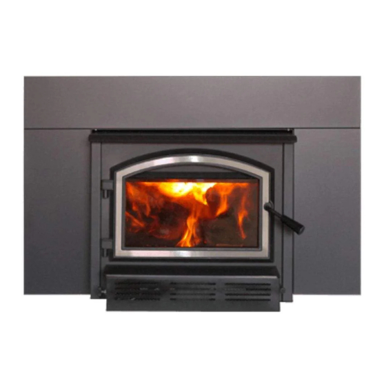
MODEL: Archway 1700 WOOD INSERT
Notice to reader: Our Archway 1700 wood insert was tested
as part of our 1.7 Series (Blackcomb II) firebox. Therefore, the
1.7 Series (Blackcomb II) is referenced throughout the
attached test report.
Publicité
Chapitres
Table des Matières

Manuels Connexes pour Empire Comfort Systems Archway 1700


Sommaire des Matières pour Empire Comfort Systems Archway 1700
- Page 1 FUEL: CORDWOOD TEST STANDARD: EPA MODEL: Archway 1700 WOOD INSERT Notice to reader: Our Archway 1700 wood insert was tested as part of our 1.7 Series (Blackcomb II) firebox. Therefore, the 1.7 Series (Blackcomb II) is referenced throughout the attached test report.
- Page 2 Subject: Comparative evaluation of the Escape 1500 Stove, Harmony 1.7 Stove, Solution 1.7 Stove, Destination 1.7-I Insert, Osburn 1700 Stove, Matrix 1700-I Insert, Inspire 1700 Stove, Inspire 1700-I Insert, Gateway 1700 Stove and Archway 1700 Insert with the previously recognized Blackcomb II Stove wood burning Stove. ...
- Page 3 Intertek Testing Services Na Ltd. Tel +1 514‐6313100 1829, 32 Avenue Fax +1 (514)631‐1133 Lachine, Quebec intertek.com In conclusion, all models evaluated respect the components of the k-list as per U.S. Environmental Protection Agency 40 CFR Part 60 Standards of Performance for New Residential Wood Heaters; Final Rule, SECTION 60.533(k). Changes made are only aesthetical and do not alter particulate emission limit.
- Page 6 Certificate Number: 132-18 Certificate Expiration Date: July 31, 2023 6. Submitting wood heaters for audit testing if selected by the EPA under §60.533(n)(l )(i) and (2)(i). Failure to comply with these requirements may result in a revocation of this approval and an enforcement action, including penalties as specified under the Clean Air Act.
- Page 7 LISTING REPORT FOR APPLICANT ISSUED: Apr 27 2018 2:35PM INSPECTION TESTS AND EVALUATION OF SBI - Series 1.7 (Blackcomb) Emissions and Efficiency - EPA (43615) RENDERED TO Stove Builder International Inc. 250, rue de Copenhague St-Augustin-de-Desmaures, QC G3A 2H3 Canada GENERAL: This report gives the results of the inspection, tests and evaluation of the above for compliance with applicable requirements of the following standards: CSA B415.1 (2010), ASTM E2515 Ed.
- Page 8 Report prepared for: Guillaume Thibodeau-Fortin (Stove Builder International Inc.) on 4/30/2018 7:18:14 AM CORRELATION FOR MULTIPLE LISTEES Applicant/Basic Listee: Stove Builder International Inc. 250, rue de Copenhague St-Augustin-de-Desmaures, QC G3A 2H3 Canada Applicant/Manufacturer(s): Stove Builder International Inc. (Laguadeloupe) Contact: Claude Pare Phone: 418-878-3040 ext 255 Fax: 418-878-3001 Email: cpare@sbi-international.com...
-
Page 9: Product Description
Report prepared for: Guillaume Thibodeau-Fortin (Stove Builder International Inc.) on 4/30/2018 7:18:14 AM PRODUCT DESCRIPTION Product Covered: SBI - Series 1.7 (Blackcomb) Emissions and Efficiency - EPA Product Description: Product covered Series 1.7 Wood Fuel Room Heaters Final emission results are as follows: Series 1.7 Model Units... - Page 10 Report prepared for: Guillaume Thibodeau-Fortin (Stove Builder International Inc.) on 4/30/2018 7:18:14 AM DRAWING INDEX Certificate of Conformity SBI - Series 1.7 (Blackcomb) Emissions and Efficiency - EPA Stove Builder International Inc. | 43615 | Rev: Apr 27 2018 2:35PM | Uncontrolled Copy Page 4 of 195...
-
Page 11: Certificate Of Conformity
Report prepared for: Guillaume Thibodeau-Fortin (Stove Builder International Inc.) on 4/30/2018 7:18:14 AM Certificate of Conformity SBI - Series 1.7 (Blackcomb) Emissions and Efficiency - EPA Certificate of Conformity Emissions – Adjustable Burn Rate Wood Burning Heater EPA 40CFR Part 60, subpart AAA, ASTM E2515 2011, CSA B415.1 2010 Certificate number: WHI18 –... -
Page 12: Manufacturing Information
Report prepared for: Guillaume Thibodeau-Fortin (Stove Builder International Inc.) on 4/30/2018 7:18:14 AM MANUFACTURING INFORMATION Product Covered The model 1.7 Series Wood Fuel Room Heater is constructed of sheet steel. The outer dimensions are 23 19/32- inches deep, 29 3/8-inches high, and 22 1/2-inches wide. The unit has a door located on the front with a viewing glass. - Page 13 Report prepared for: Guillaume Thibodeau-Fortin (Stove Builder International Inc.) on 4/30/2018 7:18:14 AM SIGNATURE PAGE Reported By: Reviewed By: Stove Builder International Inc. | 43615 | Rev: Apr 27 2018 2:35PM | Uncontrolled Copy Page 7 of 195...
- Page 14 Report prepared for: Guillaume Thibodeau-Fortin (Stove Builder International Inc.) on 4/30/2018 7:18:14 AM DRAWING INDEX 1.3 - Installation and Operation Manual English 1.5 - Installation and Operation Manual French 2 - Label Blackcomb 3 - Drawings Stove Builder International Inc. | 43615 | Rev: Apr 27 2018 2:35PM | Uncontrolled Copy Page 8 of 195...
- Page 15 Installation and Operation Manual ARCHWAY 1700 INSERT (Model WB17IN) Safety tested according to ULC S628, UL 1482 and UL 737 by an accredited laboratory. US Environmental Protection Agency phase II certified 2020 cord wood insert. CONTACT LOCAL BUILDING OR FIRE OFFICIALS ABOUT RESTRICTIONS AND INSTALLATION INSPECTION REQUIREMENTS IN THE AREA.
- Page 16 THANK YOU FOR CHOOSING THIS WOOD INSERT. The following pages provide Contact local building or fire general advice on wood officials about restrictions heating, detailed instructions and installation inspection If this insert is not for safe and effective requirements in the area. installed properly, installation, and guidance combustible materials...
-
Page 17: Table Des Matières
TABLE OF CONTENTS PART A - OPERATION AND MAINTENANCE ................7 1. Safety Information ....................... 7 2. General Information ......................8 2.1 Performances ......................8 2.2 Specifications ......................9 2.3 Dimensions ......................10 2.4 Materials ........................12 2.5 Zone Heating ......................12 2.6 Emissions and Efficiency ....................13 3. - Page 18 8. Safety Information and Standards ................... 29 8.1 Regulations Covering Insert Installation ...............29 8.2 Certification Label ......................29 9. Clearances to Combustible Material ................30 9.1 Installation of a Combustible Mantel Shelf ..............30 9.2 Floor Protection ......................30 9.3 Minimum Masonry Opening and Clearances to Combustibles ........33 10.
- Page 19 CERTIFICATION PLATE Page 6...
-
Page 20: Part A - Operation And Maintenance
PART A - OPERATION AND MAINTENANCE 1. Safety Information • This insert has been tested for use with an open door in conjunction with a fire screen, sold separately. The door may be opened, or fire screen removed only during lighting procedures or reloading. -
Page 21: General Information
2. General Information Performances Values are as measured per test method, except for the recommended heating area, firebox volume, maximum burn time and maximum heat output. Models Archway 1700 Combustion technology Non-catalytic Fuel Type Dry Cordwood Recommended heating area (sq. ft. -
Page 22: Specifications
Specifications Maximum log length 18 in (457 mm) east-west Flue outlet diameter 6 in (150 mm) Recommended connector pipe diameter 6 in (150 mm) Type of chimney ULC S635, CAN/ULC-S640, UL 1777 Baffle material C-Cast Approved for alcove installation Not applicable Approved for mobile home installation Type of door Simple, glass with cast iron frame... -
Page 23: Dimensions
Dimensions 2 3/4" 14 1/4" 70mm 361mm 26 7/8" 683mm 25 1/2" 648mm 12 3/4" 5 3/4" 324mm 145mm 6" Ø 150mm 24 5/8" 624mm Figure 1: Top View Figure 2: Side View - Minimum Insert Projection 4" 12 7/8" 103mm 328mm 9 3/8"... - Page 24 8 3/4" 221mm 17 1/4" 438mm Figure 5: Door Opening 3/16" 5/16" 19 5/8" 12" 498mm 305mm 13 3/4" 349mm Figure 6: Front View - Combustion Chamber Figure 7: Side View - Combustion Chamber Page 11...
-
Page 25: Materials
Materials The body of this insert, which is most of its weight, is carbon steel. Should it ever become necessary many years in the future, almost the entire insert can be recycled into new products, thus eliminating the need to mine new materials. The paint coating on the insert is very thin. -
Page 26: Emissions And Efficiency
The success of zone heating will depend on several factors, including the correct sizing and location of the insert, the size, layout and age of the home and the climate zone. Three-season vacation homes can usually be heated with smaller inserts than houses that are heated all winter. Emissions and Efficiency The low smoke emissions produced by the special features inside this insert firebox means that the household will release up to 90% less smoke into the outside environment than if an... -
Page 27: Log Length
Homeowners with access to both hardwood and softwood use both types for different purposes. Softer woods make good fuel for mild weather in spring and fall because they light quickly and produce less heat. Softwoods are not as dense as hardwoods so a given volume of wood contains less energy. - Page 28 Firewood with a moisture content between 15% and 20% will allow the insert to produce its highest possible efficiency. Here are some facts to consider in estimating drying time: − Firewood bought from a dealer is rarely dry enough to burn, so it is advisable to buy the wood in spring and dry it yourself;...
-
Page 29: Operating The Insert
4. Operating the Insert This wood heater has a manufacturer-set minimum low burn rate that must not be altered. It is against federal regulations to alter this setting or otherwise operate this wood heater in a manner inconsistent with operating instructions in this manual. Before using the insert, the following steps should be completed : •... -
Page 30: Blower
Blower A blower is already installed on this insert. It is located underneath the ash lip, in front of the insert. Its function is to increase airflow through the heat exchanger and improve hot air circulation in the room. When used regularly, the blower can provide a small increase in efficiency, up to 2%. -
Page 31: Lighting Fires
When lighting the heater for the first few times, it may be wise to open doors and windows to ventilate the house. Burn two or three small fires to begin the curing and conditioning process. Then build bigger and hotter fires until there is no longer paint smell from the insert. As hotter and hotter fires are burned, more of the painted surfaces reach the curing temperature of the paint. -
Page 32: Combustion Cycles
5.2.3 Two Parallel Logs Method Two spit logs are placed in the firebox with a few sheets of twisted newspapers in between the logs. Fine kindling is added across the two logs and some larger kindling across those, log cabin style. -
Page 33: Removing Ashes
Raking the coals is useful for two reasons. First, it brings them near where most of the combustion air enters the firebox. This will ignite the new load quickly. Secondly, the charcoal will not be smothered by the new load of wood. When the embers are simply spread inside the combustion chamber, the new load smoulder for a long time before igniting. -
Page 34: Fire Types
As the air intake is reduced, the burn rate decreases. This has the effect of distributing the thermal energy of the fuel over a longer period of time. In addition, the flow rate of exhaust through the appliance and flue pipe slows down, which increases the duration of the energy transfer of the exhaust gases. -
Page 35: Carbon Monoxide
5.7.4 Maximum Burn Cycle Times The burn cycle time is the period between loading wood on a coal bed and the consumption of that wood back to a coal bed of the same size. The flaming phase of the fire lasts for roughly the first half of the burn cycle and the second half is the coal bed phase during which there is little or no flame. -
Page 36: Maintenance
6. Maintenance This heater will give many years of reliable service if used and maintained properly. Internal components of the firebox such as firebricks or refractory panels, baffle and air tubes will wear over time. Defective parts should always be replaced with original parts see «Appendix 8: Exploded Diagram and Parts List». - Page 37 6.2.2 Replacement The glass used is a ceramic glass, 5/32" (4 mm) thick tested to reach temperatures up to 1400º F. If the glass breaks, it must be replaced with one having the same specification. Tempered glass or ordinary glass will not withstand the high temperatures of this unit. To remove or replace the glass (D): Remove the door from its hinges and lay it on a soft, flat surface.
-
Page 38: Door
Door In order for the insert to burn at its best efficiency, the door must provide a perfect seal with the firebox. Therefore, the gasket should be inspected periodically to check for a good seal. The tightness of the door seal can be verified by closing and latching the door on a strip of paper. The test must be performed all around the door. -
Page 39: Exhaust System
6.3.2 Gasket It is important to replace the gasket with another having the same diameter and density to maintain a good seal. Remove the door and place it face-down on something soft like a cushion of rags or a piece of carpet. Remove the old gasket from the door. -
Page 40: Sweeping The Chimney
Establish a routine for the fuel, wood burner and firing technique. Check daily for creosote build-up until experience shows how often you need to clean to be safe. Be aware that the hotter the fire, the less creosote is deposited and weekly cleaning may be necessary in mild weather even though monthly cleaning may be enough in the coldest months. -
Page 41: Part B - Installation
PART B - INSTALLATION 7. Masonry Fireplace Requirements The masonry fireplace must meet the minimum requirements found in the building code enforced locally, or the equivalent, for a safe installation. Contact the local building inspector for requirements in the area. An inspection of the fireplace should include the following: Fireplace and Chimney Condition The masonry fireplace and chimney should be inspected prior to installation, to confirm that they are free from cracks, loose mortar, creosote deposits, blockage, or other signs of deterioration. -
Page 42: Safety Information And Standards
8. Safety Information and Standards • The information given on the certification label affixed to the appliance always overrides the information published, in any other media (owner’s manual, catalogues, flyers, magazines and web sites). • Mixing of appliance components from different sources or modifying components may result in hazardous conditions. -
Page 43: Clearances To Combustible Material
9. Clearances to Combustible Material When the insert is installed so that its surfaces are at or beyond the minimum clearances specified, combustible surfaces will not overheat under normal and even abnormal operating conditions. NO PART OF THE INSERT MAY BE LOCATED CLOSER TO THE COMBUSTIBLE THAN THE MINIMUM CLEARANCE FIGURES GIVEN. - Page 44 To determine the need to add floor protection (D) beyond the hearth extension (A), the following calculation must be done using the data in «Table 4 : Data for Floor Protection Calculation» this section: D = B - G. HEARTH SLAB: HEARTH SLAB: NON-COMBUSTIBLE MATERIAL NON-COMBUSTIBLE MATERIAL...
- Page 45 9.2.3 R Value There are two ways to calculate the R-value of the floor protection. First, by adding the R-values of materials used, or by the conversion if the K factor and thickness of the floor protection are given. To calculate the total R value from R values of the materials used, simply add the R-values of materials. If the result is equal to or greater than the R-value requirements, the combination is acceptable.
-
Page 46: Minimum Masonry Opening And Clearances To Combustibles
Minimum Masonry Opening and Clearances to Combustibles COMBUSTIBLE MANTEL SHELF COMBUSTIBLE TOP SURROUND FLOOR PROTECTION Figure 25: Masonry Opening and Clearances MINIMUM CLEARANCES MAXIMUM THICKNESS 16" (406 mm) 5" (127 mm) 9" (229 mm) 12" (305 mm) 27" (686 mm) 27"... -
Page 47: The Venting System
The Venting System 10.1 General The venting system, made of the chimney and the liner inside the chimney, acts as the engine that drives the wood heating system. Even the best insert will not function safely and efficiently as intended if it is not connected to a suitable chimney and liner system. The heat in the flue gases that pass from the insert into the chimney is not waste heat. -
Page 48: Chimney Liner Installation
10.4 Chimney Liner Installation The use of a chimney liner (rigid or flexible) is RAIN CAP recommended to ensure the best performance. ensure an optimal draft, it is also strongly recommend RIGID LINER adding a minimum of 12" rigid liner between the top of 12"... - Page 49 The dealer may offer a liner fastening system, sold separately. Follow the installation instructions provided with the liner fastening system. Figure 30: Liner fastening system 10.5.2 Liner Offset Adapter A liner offset adapter, sold separately, can also be installed. This should only be installed if no other option is possible and if the total height of the fireplace and chimney is at least 20 feet.
-
Page 50: Minimum Chimney Height
10.6 Minimum Chimney Height The top of the chimney should be tall enough to be above the air turbulence caused when wind blows against the house and its roof. The chimney must extend at least 3 ft. (1 m) above the highest point of contact with the roof, and at least 2 ft.(60 cm) higher than any roof line or obstacle within a horizontal distance of 10 ft. -
Page 51: Supply Of Combustion Air
10.8 Supply of Combustion Air In Canada, wood inserts are not required to have a combustion air supply from outside. Research has shown that outside air supply do not compensate for the depressurization of the house and may not be sufficient to provide a supply of combustion air in windy weather. However, to reduce the risks against smoke spillage due to house depressurization, a carbon monoxide (CO) detector is required in the room where the insert is installed. -
Page 52: Appendix 1: Blower And Ash Lip Installation
APPENDIx 1: BLOWER AND ASH LIP INSTALLATION Install the ash lip (A) on the insert with three screws (B). Center the blower on the ash lip and push it against the firebox. Then push it until it clips. Page 39... -
Page 53: Appendix 2: Door Overlay Installation
APPENDIx 2: DOOR OVERLAY INSTALLATION Position the overlay (C) on the door frame and secure it in place from behind using the screws (D). To ease the installation, do not tighten the screws until they are all installed. Note: It is not necessary to remove the glass to install the overlay. Page 40... -
Page 54: Appendix 3: Optional Fresh Air Intake Kit Installation
APPENDIx 3: OPTIONAL FRESH AIR INTAKE KIT INSTALLATION Note : The fresh air intake kit may be installed on the right or left end side of the unit. The unused side must be covered by the plate provided in the user manual kit. Install the fresh air intake adapter (E) with four screws (F) then secure the flexible pipe (H) (not included) to the adapter using one of the pipe clamps (G). -
Page 55: Appendix 4: Optional Faceplate Installation
APPENDIx 4: OPTIONAL FACEPLATE INSTALLATION Remove the faceplate extension (A) secured between the firebox and the convection air jacket. Line up the holes of panels B, C and D and secure them together using the bolts (E) and nuts (F) provided. Page 42... - Page 56 Align the holes of the faceplate extension (A) with the holes in the faceplate panels B, C and D. Screw them using bolts (G) and nuts (H) provided. Center the insert into the fireplace opening. If necessary, adjust the height of the insert using the levelling bolts (M) on each side of the insert until the faceplate is properly seated on the floor of the hearth extension.
-
Page 57: Appendix 5: Optional Fire Screen Installation
APPENDIx 5: OPTIONAL FIRE SCREEN INSTALLATION Open the door. Hold the fire screen by the two handles and bring it close to the door opening. Lean the upper part of the fire screen against the top door opening making sure to insert the top fire screen brackets behind the primary air deflector. -
Page 58: Appendix 6: Air Tubes And Baffle Installation
APPENDIx 6: AIR TUBES AND BAFFLE INSTALLATION Starting with the rear tube, lean and insert the right end of the secondary air tube into the rear right channel hole. Then lift and insert the left end of the tube into the rear left channel. Align the notch in the left end of the tube with the key of the left air channel hole. - Page 59 Note that secondary air tubes (A) can be replaced without removing the baffle board (B) and that all tubes are identical. Page 46...
-
Page 60: Appendix 7: Removal Instructions
APPENDIx 7: REMOVAL INSTRUCTIONS For inspecting purposes, the insert may need to be removed. To remove the insert, follow these instructions: Unscrew the faceplate fastener (B) holding the faceplate (C) on the insert. Remove faceplate (C) by pulling on it. Remove the blower assembly (D). -
Page 61: Appendix 8: Exploded Diagram And Parts List
APPENDIx 8: ExPLODED DIAGRAM AND PARTS LIST 43 44 DETAIL A Page 48... - Page 62 BLACK TORX SCREW WITH FLAT HEAD TYPE F 1/4-20 X 3/4" SE70579 ASH LIP ASSEMBLY SE70576 LEFT DECORATIVE PANEL ASSEMBLY PL70587 FACEPLATE EXTENSION PL34052 LINER FIXATION BRACKET SE45977 ARCHWAY 1700 INSTRUCTIONS MANUAL KIT 44080 RHEOSTAT WITHOUT NUT (MODEL KBMS-13BV) Page 49...
- Page 63 Item Description 44087 RHEOSTAT NUT 44085 RHEOSTAT KNOB SE70580 BLOWER ASSEMBLY 60013 POWER CORD 96" X 18-3 type SJT (50 pcs per carton) 44028 CERAMIC THERMODISC F110-20F 44089 DOUBLE CAGE BLOWER 144 CFM 115V - 60Hz - 1.1A WS1744BL 29" X 44" SURROUND FOR 1700 WS1750BL 32"...
-
Page 64: Empire Limited Lifetime Warranty
EMPIRE LIMITED LIFETIME WARRANTY EMPIRE LIMITED LIFETIME WARRANTY The warranty of the manufacturer extends only to the original retail purchaser and is not transferable. This warranty covers brand new products only, which have not been altered, modified nor repaired since shipment from factory. Proof of purchase (dated bill of sale), model name and serial number must be supplied when making any warranty claim to the EMPIRE dealer. - Page 65 Empire Comfort Systems, Inc. 918 Freeburg Avenue Belleville, IL 62220 618 233.7420 www.empirecomfort.com Manufactured by : Stove Builder International inc., 250, rue de Copenhague, St-Augustin-de-Desmaures, Qc, Canada. G3A 2H3, 418-908-8002...
-
Page 66: Essais De Sécurité Faits Conformément Aux Normes
Manuel d’installation et d’opération ARCHWAY 1700 ENCASTRABLE (Modèle WB17IN) Encastrable à bois approuvé selon les exigences de l’agence de protection de l’environnement américaine EPA 2020 avec bois de corde. Essais de sécurité faits conformément aux normes ULC S628, UL 1482 et UL 737 par un laboratoire accrédité. - Page 67 MERCI D’AVOIR CHOISI CET ENCASTRABLE À BOIS. Dans les pages qui suivent Consulter le code du se trouvent des conseils bâtiment local ou contacter d’ordre général sur le le service des incendies pour Lorsque l’appareil chauffage au bois, des connaître les restrictions et n’est pas installé...
- Page 68 TABLE DES MATIÈRES PARTIE A – UTILISATION ET ENTRETIEN ................... 7 1. Sécurité ........................... 7 2. Informations générales ......................8 Performances ........................ 8 Specifications ....................... 9 Dimensions .........................10 Matériaux ........................12 Chauffage par zone ......................12 Émissions et efficacité ....................13 3. Combustibles ........................13 Essences d’arbres ......................14 Longueur des bûches ....................14 Grosseur des bûches ....................14...
- Page 69 8. Sécurité et normes ........................ 30 Règlements régissant l’installation d’un encastrable ............30 Plaque d’homologation ....................30 9. Dégagements aux matériaux combustibles ................ 31 Installation d’une tablette combustible ................31 Protection de plancher ....................32 Ouverture minimum de l’âtre et dégagements aux combustibles ........35 10.
-
Page 70: Plaque D'homologation
PLAQUE D’HOMOLOGATION Page 6... -
Page 71: Partie A - Utilisation Et Entretien
PARTIE A – UTILISATION ET ENTRETIEN 1. Sécurité • Cet encastrable a été mis à l’essai pour être utilisé la porte ouverte avec un pare-étincelles, vendu séparément. Il faut ouvrir la porte ou retirer le pare-étincelles seulement pour allumer et recharger l’encastrable. -
Page 72: Informations Générales
Performances Valeurs telles qu’obtenues en test, à l’exception de la superficie de chauffage recommandée, le volume de la chambre à combustion, le temps de combustion maximal et la puissance thermique maximale. Archway 1700 Modèle Technologie de combustion Non-catalytique Type de combustible Bûches de bois sec... -
Page 73: Specifications
Spécifications Longueur maximale des bûches 18 po (457 mm) est-ouest Diamètre de la buse de raccordement 6 po (150 mm) Diamètre du tuyau de raccordement recommandé 6 po (150 mm) Type de cheminée ULC-S635, CAN/ULC-S640, UL 1777 Matériau du coupe-feu C-Cast Approuvé... -
Page 74: Dimensions
Dimensions 2 3/4" 14 1/4" 70mm 361mm 26 7/8" 683mm 25 1/2" 648mm 12 3/4" 5 3/4" 324mm 145mm 6" Ø 150mm 24 5/8" 624mm Figure 1: Vue du dessus Figure 2: Vue de côté - Projection minimum 4" 12 7/8" 103mm 328mm 9 3/8"... - Page 75 8 3/4" 221mm 17 1/4" 438mm Figure 5: Ouverture de porte 3/16" 5/16" 19 5/8" 12" 498mm 305mm 13 3/4" 349mm Figure 6: Vue de face - Chambre à combustion Figure 7: Vue de côté - Chambre à combustion Page 11...
-
Page 76: Matériaux
Matériaux Le caisson de l’encastrable, qui représente la plus grande partie de son poids, est fait d’acier. Si cela devenait nécessaire dans plusieurs années, presque tout l’encastrable peut être recyclé en nouveaux produits, ce qui évite d’avoir à extraire du nouveau minerai. La couche de peinture de l’encastrable est très mince. -
Page 77: Émissions Et Efficacité
Bien que cet encastrable soit capable de chauffer les secteurs principaux de la maison à une température adéquate, il est fortement recommandé d’avoir aussi un système de chauffage conventionnel au mazout, au gaz ou à l’électricité comme source de chauffage complémentaire. Plusieurs facteurs feront en sorte que le chauffage par zone réussira, y compris le bon emplacement et la bonne grosseur de l’encastrable, la dimension, la disposition et l’âge de la résidence, de même que la zone climatique. -
Page 78: Essences D'arbres
• DES PRODUITS DU PAPIER, DU CARTON, DU CONTREPLAQUÉ OU DES PANNEAUX DE PARTICULES. L’INTERDICTION DE BRÛLER CES MATÉRIAUX N’INTERDIT PAS L’UTILISATION D’ALLUME FEU FABRIQUÉ À PARTIR DE PAPIER, DE CARTON, DE SCIURE DE BOIS, DE CIRE ET DE SUBSTANCES SIMILAIRES POUR ALLUMER UN FEU. BRÛLER CES MATÉRIAUX POURRAIT PRODUIRE UNE ÉMANATION DE FUMÉE TOXIQUE, RENDRE L’APPAREIL INEFFICACE ET CAUSER DE LA FUMÉE. -
Page 79: Bûches Densifiées
Bûches densifiées Les bûches densifiées faites à 100 % de sciure comprimée peuvent être brûlées, à condition de ne pas brûler trop de ces bûches à la fois. Ne pas brûler de bûches densifiées contenant de la sciure imprégnée de cire ou de bûches contenant des additifs chimiques. Suivre les instructions et les mises en garde du fabricant. -
Page 80: Utilisation De L'encastrable
4. Utilisation de l’encastrable Le taux de combustion minimum de cet appareil à bois a été défini par le fabricant et ne doit pas être modifié. Il est contre la réglementation fédérale de modifier ce réglage ou d’utiliser cet encastrable à bois d’une manière non conforme aux instructions d’utilisation de ce manuel. -
Page 81: Fonctionnement Du Ventilateur
Fonctionnement du ventilateur Un ventilateur est déjà installé sur cet encastrable. Il est situé à l’avant, sous la tablette à cendres. Le ventilateur accroît la circulation d’air dans l’échangeur de chaleur et améliore la circulation d’air chaud dans la pièce. S’il est utilisé sur une base régulière, le ventilateur peut accroître le rendement jusqu’à... -
Page 82: Combustion Efficace Du Bois
5. Combustion efficace du bois Première utilisation Deux choses se produisent lors des premières attisées: la peinture durcit et les composantes intérieures se conditionnent. Au fur et à mesure que la peinture durcit, certains éléments chimiques se vaporisent. Les vapeurs ne sont pas nocives, mais elles sentent mauvais. Les vapeurs de peinture fraîche peuvent aussi déclencher de fausses alarmes dans les détecteurs de fumée. -
Page 83: Utilisation Des Allume-Feu
Placer trois ou quatre petites bûches fendues et sèches dans la chambre à combustion. Disposer le bois d’allumage sur les bûches en deux couches à angles droits et placer une dizaine d’éclats fins sur la deuxième rangée. Il est possible d’utiliser du papier chiffonné, mais il risque de ne pas tenir en place puisqu’il a tendance à... -
Page 84: Raviver Un Feu
En alimentant le feu par cycles, la porte est ouverte moins souvent durant la combustion du bois. Ceci est un avantage puisqu’il évite que de la fumée s’échappe de l’encastrable lors de l’ouverture de la porte durant un cycle de combustion. Ceci est particulièrement vrai si la cheminée est fixée au mur extérieur de la maison. -
Page 85: Contrôle De L'admission D'air
Les cendres contiennent presque toujours des braises qui peuvent rester chaudes pendant des jours et qui libèrent du monoxyde de carbone. Les cendres doivent être placées dans un récipient en métal bien fermé. Le contenant doit être placé sur un plancher non combustible ou sur le sol, à... -
Page 86: Feu De Longue Durée
Ce type de feu est bon pour les températures modérées et devrait fournir suffisamment de chaleur pendant environ quatre heures. C’est le bon moment pour utiliser du bois mou et éviter de surchauffer la maison. 5.7.2 Feu de longue durée Pour avoir un feu qui durera jusqu’à... -
Page 87: Orientation Des Bûches
5.7.5 Orientation des bûches Dans une chambre à combustion relativement carrée, le bois peut être placé droit (extrémité des bûches visible ou nord-sud) ou sur le côté (côté des bûches visible ou est-ouest). Les charges placées droites permettent une plus grande quantité de bois à la fois. Par contre, elles se brisent en petits morceaux plus rapidement. -
Page 88: Vitre
Vitre 6.2.1 Nettoyage Dans des conditions normales, la vitre devrait rester relativement propre. Si le bois de chauffage est suffisamment sec et que les instructions d’utilisation de ce manuel sont suivies, il se formera un dépôt blanchâtre et poussiéreux sur la surface intérieure de la vitre après environ une semaine d’utilisation. -
Page 89: Joint D'étanchéité
Les deux principales causes de bris de vitre sont un placement inégal de la vitre dans la porte et un serrage excessif des vis. 6.2.3 Joint d’étanchéité Le joint est plat, encollé et est fait de fibre de verre tressée. Le joint doit être centré sur l’épaisseur du verre. - Page 90 Ajustement L’étanchéité peut être améliorée avec un ajustement simple du mécanisme de verrouillage : Retirer la goupille de retenue fendue en tirant et tournant à l’aide d’une pince. Tourner la poignée d’un tour dans le sens contraire des aiguilles d’une montre afin d’augmenter la pression entre le cadrage de la porte et la structure de l’encastrable.
-
Page 91: Système D'évacuation
Système d’évacuation La fumée de bois se condense à l’intérieur de la cheminée, formant un dépôt inflammable appelé créosote. Lorsque la créosote s’accumule dans le système d’évacuation, elle peut s’enflammer lorsqu’un feu très chaud est fait dans l’encastrable. Un feu extrêmement chaud peut progresser jusqu’à... -
Page 92: Feu De Cheminée
6.5.3 Feu de cheminée L’entretien et l’inspection régulière du système de cheminée peuvent éviter les feux de cheminée. Si un feu de cheminée se déclare, procéder comme suit : Fermer la porte et le contrôle d’admission d’air de l’encastrable; Alerter les occupants de la maison du danger; Si vous avez besoin d’aide, appeler le service d’incendies;... -
Page 93: Partie B - Installation
PARTIE B - INSTALLATION 7. Exigences pour les foyers de maçonnerie Le foyer de maçonnerie doit répondre aux exigences minimales du code du bâtiment local ou l’équivalent afin d’obtenir une installation sécuritaire. Contacter un inspecteur du bâtiment pour prendre connaissance des exigences en vigueur dans la région. L’inspection du foyer de maçonnerie devrait inclure les détails suivants : Condition du foyer et de la cheminée Avant de commencer l’installation, le foyer de maçonnerie et la cheminée devraient être inspectés... -
Page 94: Sécurité Et Normes
8. Sécurité et normes • Les informations inscrites sur la plaque d’homologation de l’appareil ont toujours préséance sur les informations contenues dans tout autre média publié (manuels, catalogues, circulaires, revues et sites web). • Mélanger des composants provenant de diverses sources ou modifier des composants peut amener des situations dangereuses. -
Page 95: Dégagements Aux Matériaux Combustibles
La plaque d’homologation est généralement située sur le côté de l’encastrable, vers l’avant. Pour y accéder, la façade devra peut-être être retirée. Par conséquent, il est recommandé de noter le numéro de série de l’appareil à la page 5 de ce manuel, car il sera nécessaire pour identifier précisément la version de l’appareil, dans le cas où... -
Page 96: Protection De Plancher
Protection de plancher Il est nécessaire d’avoir une protection de plancher fait de matériaux non combustibles respectant les mesures indiquées dans le «Tableau 3 : Protection de plancher» ci-dessous. Tableau 3 : Protection de plancher PROTECTION DE PLANCHER Canada 18" (457 mm) 16"... -
Page 97: Résistance (R) Par Pouce D'épaiseur
Tableau 4 : Données pour le calcul de la protection de plancher Extension de la chemise voir section De niveau 4" G = (A-C) Saillie Dimension de 7⅛" 9.2.1 et avec la Maximale l’extension de l’âtre (102 mm) D=B-G (181 mm) 9.2.2 façade 1 ⅜"... - Page 98 MATÉRIEL CONDUCTIVITÉ (K) RÉSISTANCE (R) PAR PAR POUCE POUCE D’ÉPAISEUR Wonderboard® 3.23 0.31 Mortier de ciment 5.00 Brique commune 5.00 Brique de parement 9.00 0.11 Marbre 14.3 – 20.00 0.07 – 0.05 Tuile céramique 12.5 0.008 Béton 1.050 0.950 Laine céramique d’isolation 0.320 3.120 Calcaire...
-
Page 99: Ouverture Minimum De L'âtre Et Dégagements Aux Combustibles
Ouverture minimum de l’âtre et dégagements aux combustibles TABLETTE COMBUSTIBLE PAREMENT SUPÉRIEUR COMBUSTIBLE PROTECTION DE PLANCHER Figure 25: Ouverture de l’âtre et dégagements aux combustibles DÉGAGEMENTS PROFONDEUR MINIMUMS MAXIMALE 16" (406 mm) 5" (127 mm) 9" (229 mm) 12" (305 mm) 27"... -
Page 100: Le Système D'évacuation
Le système d’évacuation 10.1 Conseils généraux Le système d’évacuation, composé de la cheminée et de la gaine à l’intérieur de la cheminée, agit comme le moteur qui entraîne le système de chauffage au bois. Même le meilleur des encastrables ne fonctionnera pas de façon aussi sécuritaire et efficace s’il n’est pas raccordé à une cheminée adéquate. -
Page 101: Installation De La Gaine
10.4 Installation de la gaine L’utilisation d’une gaine de cheminée (rigide ou flexible) CHAPEAU est recommandée pour obtenir le meilleur rendement possible. Pour garantir une tire optimale, il est aussi GAINE RIGIDE fortement recommandé d’ajouter une gaine rigide d’une 12" SOLIN 305mm MIN. -
Page 102: Adaptateur Pour Déviation De Gaine
Le détaillant peut fournir un système d’attache pour gaine, vendu séparément. Suivre les instructions d’installation fournies avec l’ensemble. Figure 30: Système d’attache pour gaine 10.5.2 Adaptateur pour déviation de gaine Un adaptateur pour déviation de gaine, vendu séparément, peut être installé. L’adaptateur ne devrait être installé... -
Page 103: Hauteur Minimale De La Cheminée
10.6 Hauteur minimale de la cheminée L’extrémité cheminée doit être suffisamment haute pour dépasser turbulence d’air causée par le vent contre la maison et le toit. La cheminée doit dépasser d’au moins 3 pi. (1 mètre) au-dessus de son point de sortie du toit le plus haut et d’au moins 2 pi. -
Page 104: Apport D'air De Combustion
10.8 Apport d’air de combustion Au Canada, les encastrables à bois n’ont pas à être munis d’un apport d’air de combustion de l’extérieur. Les recherches ont démontré que ces apports ne compensent pas la dépressurisation de la maison et peuvent ne pas suffire à fournir un apport d’air de combustion par temps venteux. Cependant, pour diminuer les risques associés à... -
Page 105: Annexe 1: Installation Du Ventilateur Et De La Tablette À Cendres
ANNExE 1: INSTALLATION DU VENTILATEUR ET DE LA TABLETTE À CENDRES Installer la tablette à cendres (A) avec les vis (B). Centrer le ventilateur sur la tablette à cendres et pousser vers l’encastrable jusqu’à ce qu’un clic se fasse entendre. Page 41... -
Page 106: Annexe 2: Installation Du Revêtement De Porte
ANNExE 2: INSTALLATION DU REVÊTEMENT DE PORTE Positionner le revêtement (C) sur la porte et le visser en place par l’arrière en utilisant les écrous (D). Pour faciliter l’installation, ne pas visser complètement les écrous avant qu’ils ne soient tous installés. Note: Il n’est pas nécessaire de retirer la vitre pour installer le revêtement de porte. -
Page 107: Annexe 3: Installation De L'entrée D'air Optionnel
ANNExE 3: INSTALLATION DE L’ENTRÉE D’AIR OPTIONNEL Note : L’entrée d’air peut être installée du côté gauche ou droit de l’appareil. Le côté non utilisé doit être couvert par la plaque fournie dans l’ensemble de manuel. Installer l’adaptateur d’admission d’air frais (E) avec quatre vis (F), puis fixer le tuyau flexible (non fourni) à... -
Page 108: Annexe 4: Installation De La Façade Optionnelle
ANNExE 4: INSTALLATION DE LA FAÇADE OPTIONNELLE Retirer l’extension de façade (A) qui est fixée entre la chambre à combustion et l’enveloppe de convection. Aligner les trous des panneaux B, C et D et les fixer ensemble à l’aide des boulons (E) et des écrous (F) fournis. - Page 109 Aligner les trous de l’extension de façade (A) avec les trous des panneaux de façade B, C et D. Visser à l’aide des boulons (G) et des écrous (H) fournis. Centrer l’encastrable dans l’ouverture du foyer. Si nécessaire, ajuster la hauteur de l’encastrable à l’aide des boulons élévateurs (M) de chaque côté...
-
Page 110: Annexe 5: Installation Du Pare-Étincelles Optionnel
ANNExE 5: INSTALLATION DU PARE-ÉTINCELLES OPTIONNEL Ouvrir la porte. Tenir le pare-étincelles à l’aide des deux poignées et l’approcher de l’ouverture de la porte. Incliner la partie supérieure du pare-étincelles vers le haut de l’ouverture de porte. Ensuite, insérer les deux crochets au haut du pare-étincelles derrière le déflecteur d’air primaire. Soulever le pare-étincelles et pousser la partie inférieure vers l’encastrable puis laisser descendre jusqu’à... -
Page 111: Annexe 6: Installation Des Tubes D'air Et Du Coupe-Feu
ANNExE 6: INSTALLATION DES TUBES D’AIR ET DU COUPE-FEU En commençant vers l’arrière, incliner et insérer le tube d’air secondaire arrière dans le trou du fond de la canalisation droite. Ensuite, lever et pousser le tube vers la gauche dans le trou correspondant de la canalisation de gauche. - Page 112 Prendre note que n’importe quel tube (A) peut être remplacé sans retirer le coupe-feu (B) et que tous les tubes sont identiques. Page 48...
-
Page 113: Annexe 7: Instructions De Désinstallation
ANNExE 7: INSTRUCTIONS DE DÉSINSTALLATION Pour les besoins d’inspection, il est possible que l’encastrable nécessite d’être retiré de son emplacement. Pour le retirer, suivre les instructions suivantes: • Dévisser la vis (B) attachant la façade (C) à l’encastrable. • Retirer la façade (C) en la tirant. •... -
Page 114: Annexe 8: Vue Explosée Et Liste De Pièces
ANNExE 8: VUE ExPLOSÉE ET LISTE DE PIÈCES 43 44 DETAIL A Page 50... - Page 115 TABLETTE À CENDRE ASSEMBLÉE SE70576 CÔTÉ DÉCORATIF GAUCHE ASSEMBLÉ PL70587 EXTENSION DE FAÇADE PL34052 ÉQUERRE DE FIXATION POUR GAINE SE45977 KIT DE MANUEL D'INSTRUCTIONS ARCHWAY 1700 44080 RHÉOSTAT SANS ÉCROU 44087 ÉCROU DU RHÉOSTAT 44085 BOUTON DE RHÉOSTAT Page 51...
- Page 116 Item Description Qté SE70580 VENTILATEUR ASSEMBLÉ 60013 CORDON D'ALIMENTATION 96" X 18-3 Gaine SJT 44028 THERMODISQUE F110-20F EN CÉRAMIQUE 44089 VENTILATEUR CAGE DOUBLE 144 PCM 115V - 60Hz - 1.1A WS1744BL ENSEMBLE DE FAÇADE 29" X 44" WS1750BL ENSEMBLE DE FAÇADE 32" X 50" PL70640 FAÇADE CÔTÉ...
-
Page 117: Garantie À Vie Limitée Empire
GARANTIE À VIE LIMITÉE EMPIRE GARANTIE À VIE LIMITÉE EMPIRE La garantie du fabricant ne s’applique qu’à l’acheteur au détail original et n’est pas transférable. La présente garantie ne couvre que les produits neufs qui n’ont pas été modifiés, altérés ou réparés depuis leur expédition de l’usine. Il faut fournir une preuve d’achat (facture datée), le nom du modèle et le numéro de série au détaillant lors d’une réclamation sous garantie. - Page 118 Empire Comfort Systems, Inc. 918 Freeburg Avenue Belleville, IL 62220 618 233.7420 www.empirecomfort.com Fabriqué par : Stove Builder International inc., 250, rue de Copenhague, St-Augustin-de-Desmaures, Qc, Canada. G3A 2H3, 418-908-8002...
- Page 119 Report prepared for: Guillaume Thibodeau-Fortin (Stove Builder International Inc.) on 4/30/2018 7:18:14 AM TESTING INFORMATION Test Report 103328128MTL-001 The SBI Model 1.7 Series Wood Fuel Room Heater has been found to be in compliance with the applicable performance requirements of the following criteria: “CSA B415.1-2010(R2015) – Performance Testing of Solid- Fuel-Burning Heating Appliances”, ASTM E2515-2011-Standard test method for determination of particulate matter emissions collected by a dilution tunnel, ASTM E3053-2017- Standard test method for determining particulate matter emissions from wood heaters using cord wood test fuel.
- Page 120 Report prepared for: Guillaume Thibodeau-Fortin (Stove Builder International Inc.) on 4/30/2018 7:18:14 AM SIGNATURE PAGE Reported By: Reviewed By: Stove Builder International Inc. | 43615 | Rev: Apr 27 2018 2:35PM | Uncontrolled Copy Page 136 of 195...
- Page 121 Report prepared for: Guillaume Thibodeau-Fortin (Stove Builder International Inc.) on 4/30/2018 7:18:14 AM DRAWING INDEX Appendix I - EPA Correspondance Test report 103328128MTL-001 Stove Builder International Inc. | 43615 | Rev: Apr 27 2018 2:35PM | Uncontrolled Copy Page 137 of 195...
- Page 122 Report prepared for: Guillaume Thibodeau-Fortin (Stove Builder International Inc.) on 4/30/2018 7:18:14 AM Appendix I - EPA Correspondance Stove Builder International Inc. | 43615 | Rev: Apr 27 2018 2:35PM | Uncontrolled Copy Page 138 of 195...
- Page 123 Report prepared for: Guillaume Thibodeau-Fortin (Stove Builder International Inc.) on 4/30/2018 7:18:14 AM Appendix I - EPA Correspondance (2 of 16) Stove Builder International Inc. | 43615 | Rev: Apr 27 2018 2:35PM | Uncontrolled Copy Page 139 of 195...
- Page 124 Report prepared for: Guillaume Thibodeau-Fortin (Stove Builder International Inc.) on 4/30/2018 7:18:14 AM Appendix I - EPA Correspondance (3 of 16) Stove Builder International Inc. | 43615 | Rev: Apr 27 2018 2:35PM | Uncontrolled Copy Page 140 of 195...
- Page 125 Report prepared for: Guillaume Thibodeau-Fortin (Stove Builder International Inc.) on 4/30/2018 7:18:14 AM Appendix I - EPA Correspondance (4 of 16) Stove Builder International Inc. | 43615 | Rev: Apr 27 2018 2:35PM | Uncontrolled Copy Page 141 of 195...
- Page 126 Report prepared for: Guillaume Thibodeau-Fortin (Stove Builder International Inc.) on 4/30/2018 7:18:14 AM Appendix I - EPA Correspondance (5 of 16) Stove Builder International Inc. | 43615 | Rev: Apr 27 2018 2:35PM | Uncontrolled Copy Page 142 of 195...
- Page 127 Report prepared for: Guillaume Thibodeau-Fortin (Stove Builder International Inc.) on 4/30/2018 7:18:14 AM Appendix I - EPA Correspondance (6 of 16) Stove Builder International Inc. | 43615 | Rev: Apr 27 2018 2:35PM | Uncontrolled Copy Page 143 of 195...
- Page 128 Report prepared for: Guillaume Thibodeau-Fortin (Stove Builder International Inc.) on 4/30/2018 7:18:14 AM Appendix I - EPA Correspondance (7 of 16) Stove Builder International Inc. | 43615 | Rev: Apr 27 2018 2:35PM | Uncontrolled Copy Page 144 of 195...
- Page 129 Report prepared for: Guillaume Thibodeau-Fortin (Stove Builder International Inc.) on 4/30/2018 7:18:14 AM Appendix I - EPA Correspondance (8 of 16) Stove Builder International Inc. | 43615 | Rev: Apr 27 2018 2:35PM | Uncontrolled Copy Page 145 of 195...
- Page 130 Report prepared for: Guillaume Thibodeau-Fortin (Stove Builder International Inc.) on 4/30/2018 7:18:14 AM Appendix I - EPA Correspondance (9 of 16) Stove Builder International Inc. | 43615 | Rev: Apr 27 2018 2:35PM | Uncontrolled Copy Page 146 of 195...
- Page 131 Report prepared for: Guillaume Thibodeau-Fortin (Stove Builder International Inc.) on 4/30/2018 7:18:14 AM Appendix I - EPA Correspondance (10 of 16) Stove Builder International Inc. | 43615 | Rev: Apr 27 2018 2:35PM | Uncontrolled Copy Page 147 of 195...
- Page 132 Report prepared for: Guillaume Thibodeau-Fortin (Stove Builder International Inc.) on 4/30/2018 7:18:14 AM Appendix I - EPA Correspondance (11 of 16) Stove Builder International Inc. | 43615 | Rev: Apr 27 2018 2:35PM | Uncontrolled Copy Page 148 of 195...
- Page 133 Report prepared for: Guillaume Thibodeau-Fortin (Stove Builder International Inc.) on 4/30/2018 7:18:14 AM Appendix I - EPA Correspondance (12 of 16) Stove Builder International Inc. | 43615 | Rev: Apr 27 2018 2:35PM | Uncontrolled Copy Page 149 of 195...
- Page 134 Report prepared for: Guillaume Thibodeau-Fortin (Stove Builder International Inc.) on 4/30/2018 7:18:14 AM Appendix I - EPA Correspondance (13 of 16) Stove Builder International Inc. | 43615 | Rev: Apr 27 2018 2:35PM | Uncontrolled Copy Page 150 of 195...
- Page 135 Report prepared for: Guillaume Thibodeau-Fortin (Stove Builder International Inc.) on 4/30/2018 7:18:14 AM Appendix I - EPA Correspondance (14 of 16) Stove Builder International Inc. | 43615 | Rev: Apr 27 2018 2:35PM | Uncontrolled Copy Page 151 of 195...
- Page 136 Report prepared for: Guillaume Thibodeau-Fortin (Stove Builder International Inc.) on 4/30/2018 7:18:14 AM Appendix I - EPA Correspondance (15 of 16) Stove Builder International Inc. | 43615 | Rev: Apr 27 2018 2:35PM | Uncontrolled Copy Page 152 of 195...
- Page 137 Report prepared for: Guillaume Thibodeau-Fortin (Stove Builder International Inc.) on 4/30/2018 7:18:14 AM Appendix I - EPA Correspondance (16 of 16) Stove Builder International Inc. | 43615 | Rev: Apr 27 2018 2:35PM | Uncontrolled Copy Page 153 of 195...
- Page 138 Report prepared for: Guillaume Thibodeau-Fortin (Stove Builder International Inc.) on 4/30/2018 7:18:14 AM Test report 103328128MTL-001 REPORT NUMBER: 103328128MTL-001 REPORT DATE: December 27, 2017 EVALUATION CENTER Intertek Testing Services NA Inc. 1829 32 Avenue Montreal (Lachine), QC Canada H8T 3J1 RENDERED TO Stove Builder International Inc.
- Page 139 Report prepared for: Guillaume Thibodeau-Fortin (Stove Builder International Inc.) on 4/30/2018 7:18:14 AM Test report 103328128MTL-001 (2 of 18) Stove Builder International Inc. Date: December 27, 2017 Project No. G103328128 Page 2 of 18 Contents INTRODUCTION ........................ 4 PURPOSE OF TEST ..........................4 LABORATORY............................
- Page 140 Report prepared for: Guillaume Thibodeau-Fortin (Stove Builder International Inc.) on 4/30/2018 7:18:14 AM Test report 103328128MTL-001 (3 of 18) Stove Builder International Inc. Date: December 27, 2017 Project No. G103328128 Page 3 of 18 IV. SAMPLING SYSTEMS ......................12 IV.A. SAMPLING LOCATIONS ........................12 IV.A.(1) DILUTION TUNNEL ........................
-
Page 141: Introduction
Report prepared for: Guillaume Thibodeau-Fortin (Stove Builder International Inc.) on 4/30/2018 7:18:14 AM Test report 103328128MTL-001 (4 of 18) Stove Builder International Inc. Date: December 27, 2017 Project No. G103328128 Page 4 of 18 INTRODUCTION Intertek Testing Services NA (Intertek) has conducted testing for Stove Builder International Inc., on model 1.7 Series Wood Burning Room Heater to evaluate all applicable performance requirements included in “Determination of particulate matter emissions from wood heaters.”... -
Page 142: I.dreport Organization
Report prepared for: Guillaume Thibodeau-Fortin (Stove Builder International Inc.) on 4/30/2018 7:18:14 AM Test report 103328128MTL-001 (5 of 18) Stove Builder International Inc. Date: December 27, 2017 Project No. G103328128 Page 5 of 18 REPORT ORGANIZATION This report includes summaries of all data necessary to determine compliance with the regulations. -
Page 143: Ii.binformation Log
Report prepared for: Guillaume Thibodeau-Fortin (Stove Builder International Inc.) on 4/30/2018 7:18:14 AM Test report 103328128MTL-001 (6 of 18) Stove Builder International Inc. Date: December 27, 2017 Project No. G103328128 Page 6 of 18 II.B INFORMATION LOG II.B(1) TEST STANDARD On November 27 to November 30 , the unit was tested for EPA emissions. -
Page 144: Ii.ddescription Of Test Runs
Report prepared for: Guillaume Thibodeau-Fortin (Stove Builder International Inc.) on 4/30/2018 7:18:14 AM Test report 103328128MTL-001 (7 of 18) Stove Builder International Inc. Date: December 27, 2017 Project No. G103328128 Page 7 of 18 II.D DESCRIPTION OF TEST RUNS RUN #1 Low burn rate Stove lighting: 6.5 lbs Split the start-up fuel log into 6 pieces. -
Page 145: Run #3 Medium Burn Rate
Report prepared for: Guillaume Thibodeau-Fortin (Stove Builder International Inc.) on 4/30/2018 7:18:14 AM Test report 103328128MTL-001 (8 of 18) Stove Builder International Inc. Date: December 27, 2017 Project No. G103328128 Page 8 of 18 Pre-load (high burn): 14 lbs When there is coal bed of 1.5 lb left, break ashes and level coal bed, then add pre-load in an East-West configuration divided in 2 columns: 2 logs in the back and 2 logs in the front. -
Page 146: Run #4 Medium Burn Rate
Report prepared for: Guillaume Thibodeau-Fortin (Stove Builder International Inc.) on 4/30/2018 7:18:14 AM Test report 103328128MTL-001 (9 of 18) Stove Builder International Inc. Date: December 27, 2017 Project No. G103328128 Page 9 of 18 RUN #4 Medium burn rate Note: For this test run, according to WK47329-14, the sampling starts as soon as the kindling is ignited (cold start). Stove lighting: 6.5 lbs Split the start-up fuel log into 6 pieces. - Page 147 Report prepared for: Guillaume Thibodeau-Fortin (Stove Builder International Inc.) on 4/30/2018 7:18:14 AM Test report 103328128MTL-001 (10 of 18) Stove Builder International Inc. Date: December 27, 2017 Project No. G103328128 Page 10 of 18 TABLE 2 – WEIGHTED AVERAGE CALCULATION (CO) Heat Test...
- Page 148 Report prepared for: Guillaume Thibodeau-Fortin (Stove Builder International Inc.) on 4/30/2018 7:18:14 AM Test report 103328128MTL-001 (11 of 18) Stove Builder International Inc. Date: December 27, 2017 Project No. G103328128 Page 11 of 18 TABLE 5 - DILUTION TUNNEL DUAL TRAIN PRECISION Sample Ratios Total Emissions (g) g/kg...
-
Page 149: Process Description
Report prepared for: Guillaume Thibodeau-Fortin (Stove Builder International Inc.) on 4/30/2018 7:18:14 AM Test report 103328128MTL-001 (12 of 18) Stove Builder International Inc. Date: December 27, 2017 Project No. G103328128 Page 12 of 18 III. PROCESS DESCRIPTION III.A TEST SET-UP DESCRIPTON A 6”... -
Page 150: Iv.a.(1) Dilution Tunnel
Report prepared for: Guillaume Thibodeau-Fortin (Stove Builder International Inc.) on 4/30/2018 7:18:14 AM Test report 103328128MTL-001 (13 of 18) Stove Builder International Inc. Date: December 27, 2017 Project No. G103328128 Page 13 of 18 IV.A.(1) DILUTION TUNNEL Stove Builder International Inc. | 43615 | Rev: Apr 27 2018 2:35PM | Uncontrolled Copy Page 166 of 195... -
Page 151: Iv.b. Operational Drawings
Report prepared for: Guillaume Thibodeau-Fortin (Stove Builder International Inc.) on 4/30/2018 7:18:14 AM Test report 103328128MTL-001 (14 of 18) Stove Builder International Inc. Date: December 27, 2017 Project No. G103328128 Page 14 of 18 IV.B. OPERATIONAL DRAWINGS IV.B.(1). DILUTION TUNNEL SAMPLE SYSTEMS IV.B. -
Page 152: Particulate Sampling
Report prepared for: Guillaume Thibodeau-Fortin (Stove Builder International Inc.) on 4/30/2018 7:18:14 AM Test report 103328128MTL-001 (15 of 18) Stove Builder International Inc. Date: December 27, 2017 Project No. G103328128 Page 15 of 18 V. SAMPLING METHODS V.A. PARTICULATE SAMPLING Particulates were sampled in strict accordance with ASTM E2515-2011. -
Page 153: Vi.a.(2). Stack Sample Rotameter
Report prepared for: Guillaume Thibodeau-Fortin (Stove Builder International Inc.) on 4/30/2018 7:18:14 AM Test report 103328128MTL-001 (16 of 18) Stove Builder International Inc. Date: December 27, 2017 Project No. G103328128 Page 16 of 18 VI.A.(2). STACK SAMPLE ROTAMETER The stack sample rotameter is checked by running three tests at each flow rate used during the test program. -
Page 154: Conclusion
Report prepared for: Guillaume Thibodeau-Fortin (Stove Builder International Inc.) on 4/30/2018 7:18:14 AM Test report 103328128MTL-001 (17 of 18) Stove Builder International Inc. Date: December 27, 2017 Project No. G103328128 Page 17 of 18 VI.B.(2). TUNNEL VELOCITY/FLOW MEASUREMENT The tunnel velocity is calculated from a center point Pitot tube signal multiplied by an adjustment factor. -
Page 155: Revision Summary
Report prepared for: Guillaume Thibodeau-Fortin (Stove Builder International Inc.) on 4/30/2018 7:18:14 AM Test report 103328128MTL-001 (18 of 18) Stove Builder International Inc. Date: December 27, 2017 Project No. G103328128 Page 18 of 18 REVISION SUMMARY DATE SUMMARY Stove Builder International Inc. | 43615 | Rev: Apr 27 2018 2:35PM | Uncontrolled Copy Page 171 of 195...