Table des Matières
Publicité
Les langues disponibles
Les langues disponibles
Liens rapides
Deutsch
English
Français
ProLine P52000 VPD
1
Betriebsanleitung
Spannungsmelder zur Spannungsüberwachung
37
User Manual
High-Voltage Presence Detectors
73
Manuel utilisateur
Détecteurs de haute tension
Aktuelle Produktinformationen: www.knick.de
Latest Product Information: www.knick.de
Informations produit actualisées : www.knick.de
Publicité
Chapitres
Table des Matières

Sommaire des Matières pour Knick ProLine P52000 VPD
- Page 1 ProLine P52000 VPD Deutsch Betriebsanleitung Spannungsmelder zur Spannungsüberwachung English User Manual High-Voltage Presence Detectors Français Manuel utilisateur Détecteurs de haute tension Aktuelle Produktinformationen: www.knick.de Latest Product Information: www.knick.de Informations produit actualisées : www.knick.de...
-
Page 2: Table Des Matières
Inhalt Sicherheitshinweise ............4 Zu Ihrer Sicherheit beachten! ................4 Symbole, Kennzeichen und Abkürzungen ..........5 Bestimmungsgemäßer Gebrauch ........6 Typische Einsatzgebiete ..................6 Typschilder ......................7 UL-Typschild ......................8 Produktspektrum ............... 9 P52*00 ........................9 Funktionsbeschreibung ........... 10 Spannungsdetektion ..................10 Schaltschwellen ....................11 Weitbereichsnetzteil ..................11 Inbetriebnahme .............. - Page 3 Inhalt Technische Daten.............. 21 Anschlussbeispiele ............26 Maßzeichnungen ..............28 Schaltverhalten Relais-Ausgang ........29 Wartung, Fehlersuche, Entsorgung ........30 Reparatur......................30 Warenrücksendung ..................30 Reinigung ......................30 Erste Maßnahmen zur Fehlersuche ............30 Lagerung ......................30 Normen und Richtlinien ........... 31 EU-Konformitätserklärung ................31 Werksprüfzeugnis ...................
-
Page 4: Sicherheitshinweise
Sicherheitshinweise WARNUNG! Berührungsgefährliche Spannungen! Werden die optionalen Schutzhauben nicht verwendet, ist bei Anwendun- gen mit hohen Arbeitsspannungen auf genügend Abstand bzw. Isolation zu Nebengeräten und auf Berührungsschutz zu achten! VORSICHT! Schutz- und Sicherheitseinrichtungen! Den Spannungsmelder ausschließlich bestimmungsgemäß einsetzen! Andernfalls können die Schutz- und Sicherheitseinrichtungen des Spannungsmelders versagen! VORSICHT! Eignungsprüfung durch Systemhersteller und Betreiber! Die Eignung und die korrekte Verwendung des Spannungsmelders muss... -
Page 5: Symbole, Kennzeichen Und Abkürzungen
Sicherheitshinweise Symbole, Kennzeichen und Abkürzungen Erläuterungen der Symbole und Kennzeichen auf dem Spannungsmelder oder in der Betriebsanleitung: ProLine ® Symbole auf dem Spannungsmelder und in der Betriebsanleitung High-Voltage Transducer LISTE Type P51100K11-M1M/11 Power 24 to 230 V Symbol Bedeutung DC: -30 % / 0000000 ES01 AC: -20 % /... -
Page 6: Bestimmungsgemäßer Gebrauch
Bestimmungsgemäßer Gebrauch Bestimmungsgemäßer Gebrauch Die Spannungsmelder der Produktlinie ProLine P52*00 VPD erfassen Span- nungen auf Schienenfahrzeugen sowie in Bahnunterwerken und Industrie- anlagen. Bei Überschreitung einer Schaltschwelle wird ein Halbleiterschalter ausgelöst und dieser Zustand zusätzlich mittels LED am Produkt angezeigt. Bei Mehrbereichsprodukten können bis zu 10 verschiedene vordefinierte Schwellwerte mittels Drehschalter ausgewählt werden. -
Page 7: Typschilder
Bestimmungsgemäßer Gebrauch Typschilder Folgende Angaben sind unter anderem auf den Typschildern zur Kennzeich- nung angebracht: • Die Kennzeichnung der Schaltschwellen • Die Prüfspannungen • Durch den Drehschalter S1 einstellbare Schaltschwellen (außer Fest- bereichstyp) • Die Informationen zum Anschluss der Hilfsenergie Hinweis: Die Angaben auf dem Typschild des Spannungsmelders sind maß- geblich. -
Page 8: Ul-Typschild
nostics Monitor Output Bestimmungsgemäßer Gebrauch ProLine High-Voltage Transducer Type P52100K11-M6M/11 Power 0000000 ES01 UL-Typschild 14163 Berlin Made in Germany Beispieldarstellung Isolation Routine Test O Operating Tem Additional Input Ratings to UL 347 nnnnn / 0000000 / jjww Types Input Ranges Input Load Rated Isolation*... -
Page 9: Produktspektrum
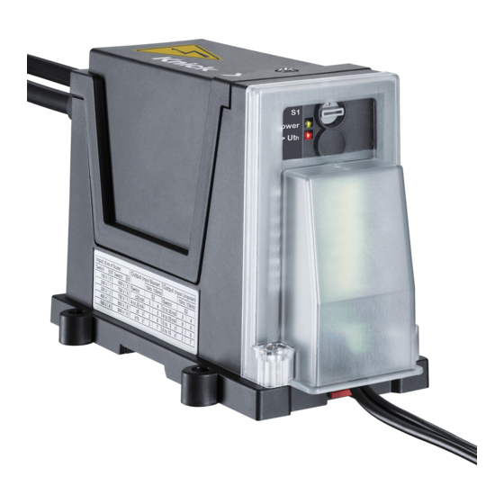
Produktspektrum P52*00 Spannungsmelder für hohe Eingangsspannungen. Die Produktvarianten decken einen Eingangsbereich (Differenz spannung) von ± 50 V bis ± 4200 V ab, bei einer maximalen Arbeitsspannung bis zu 3,6 kV (sichere Trennung durch verstärkte Isolierung) bzw. 4,8 kV (Basisisolierung). ProLine High-Voltage Presence Detector Power Type P52100K11-M00001R/01 Power... -
Page 10: Funktionsbeschreibung
Funktionsbeschreibung Legende: Anschluss der Hilfs energie (Power) (A) Ausgang (B) Drehschalter S1 (C) LEDs zur Signalisierung (D) Eingang (Anschluss der Hoch- spannung) (E) Spannungsdetektion Das Produkt detektiert DC-Spannungen . Der Betrag des Eingangssignals wird mit einem Schwellwert verglichen und die daraus resultierende binäre Information galvanisch getrennt auf den Ausgangskreis übertragen. -
Page 11: Schaltschwellen
Funktionsbeschreibung Das Produkt verfügt über eine 3-Port-Trennung, also eine vollständige galva- nische Trennung zwischen Eingang, Ausgang und Hilfsenergie. Das Gehäu- sematerial besteht aus silikonfreien Gehäusewerkstoffen. Die Isolationsei- genschaften werden u. a. durch Verguss mit einem silikonfreien Polyurethan-Gießharz erreicht. Schaltschwellen Die Schaltschwellen sind bei Mehrbereichstypen mit Hilfe eines Dreh- schalters umschaltbar. -
Page 12: Inbetriebnahme
Bei Unklarheiten vor Beginn der Installation oder Inbetriebnahme kontaktie- ren Sie einen unserer Service-Techniker: telefonisch: +49 30 80191-0 oder per Kontaktformular: www.knick.de > Kontakt > E-Mail an Knick oder direkt per E-Mail an: info@knick.de WARNUNG! Berührungsgefährliche Spannungen! Bei Anwendungen mit hohen Arbeitsspannungen auf genügend Abstand bzw. -
Page 13: Installation
Inbetriebnahme Installation Lieferumfang Die Lieferung auf Transportschäden und Vollständigkeit kontrollieren! • Spannungsmelder in Transportverpackung • Unterlegscheiben und selbstsichernde Muttern (M5) für den Hoch- spannungsanschluss • Steckerteil 2-polig (Push-In) für Hilfsenergie • Steckerteil 8-polig (Push-In) für Ausgang • Dokumentation • Werksprüfzeugnis Bei Spannungsmeldern mit Schutzhauben (ZU 1030): •... - Page 14 Inbetriebnahme WARNUNG! Berührungsgefährliche Spannungen! Werden die optionalen Schutzhauben nicht verwendet, ist bei Anwendun- gen mit hohen Arbeitsspannungen auf genügend Abstand bzw. Isolation zu Nebengeräten und auf Berührungsschutz zu achten! Mit der korrekten Installation aller isolierten Leitungen, Kabeltüllen und Schutzhauben ist ein Berührungsschutz vor gefährlichen Spannungen gegeben.
- Page 15 Inbetriebnahme Montagebeispiel: Spannungsmelder auf Hutschiene TS 35 montiert – Eingang oben, Ausgang unten F F F F F F Unterseite des Spannungsmelders Die Hutschienenklammer (F) mit beiden Daumen in Pfeilrichtung bis zum Einrasten öffnen. Nach dem Aufsetzen des Spannungsmelders auf die Hut- schiene, die Hutschienenklammer wieder schließen.
-
Page 16: Anschluss An Den Messkreis
Inbetriebnahme Anschluss an den Messkreis VORSICHT! Die Montage der Hochspannungsleitung beachten! Die Hochspannungsleitung wie in der Abb. S. 16 gezeigt führen. Die Spezifikation der Hochspannungsleitung: • Reine Kupferleitung • Querschnitt 1,5 mm bis 16 mm z. B. Huber & Suhner RADOX® 9 GKW-AX 3600V M single core Übersicht der Hochspannungseingangsklemmen (HV) Signal Anschluss... - Page 17 Inbetriebnahme 6. Das Gehäuse mit vier M6-Schrauben und jeweils einer Unterleg- scheibe (L) auf einer ebenen Montagefläche befestigen. Das empfohlene Drehmoment von 2 Nm beachten.
-
Page 18: Übersicht Der Klemmen- Und Anschlussbelegung
Inbetriebnahme Übersicht der Klemmen- und Anschlussbelegung Power Power Power Power > Ut Diag Diag > Ut Legende: Drehschalter S1 (C) I/U + I/U + LEDs (D) Do Not Connect – – Ausgang (B) Do Not Connect U – U – Prüfbuchsen 1-10 (Q) Do Not Connect... -
Page 19: Anschluss Der Leitungen Für Ausgang Und Hilfsenergie
Inbetriebnahme Anschluss der Leitungen für Ausgang und Hilfsenergie Die Leitungen entsprechend der Klemmen- und Anschlussbelegung montie- ren. Starre Leitungen bzw. feindrähtige Leitungen mit Aderendhülsen kön- nen direkt eingeschoben werden (Push-In). Bei feindrähtigen Leitungen ohne Ader endhülsen muss beim Einschieben die orangefarbene Verriege- lung mit einem Schraubendreher heruntergedrückt werden. -
Page 20: Schutzhauben
Inbetriebnahme Schutzhauben Das optionale Zubehör ist je nach Produktvariante im Lieferumfang enthal- ten oder kann separat bestellt werden: • Set mit Schutzhauben (Berührungs-, Staub- und Verschmutzungsschutz): – Schutzhaube (P) für die Eingangsklemmen (Hochspannung) – Kabeltüllen (G) für die Hochspannungsleitungen (Hochspannungseingang) –... -
Page 21: Technische Daten
Technische Daten Eingang ProLine P52*00 Schaltschwellen 50 V … 4200 V ProLine P52100 50 V … 1800 V ProLine P52000 Überlastbarkeit ± 1350 V kurzzeitig (1 s) ± 2700 V 50 ... 900 V ProLine P52000 Typen ± 2000 V kurzzeitig (1 s) ±... - Page 22 Technische Daten Schaltfunktion/Ausgang Signalisierung Ein- potentialfreier Halbleiterschalter (P-schaltend, M-schaltend) angelehnt gangssignal über- an EN 61131-2 (SPS), Kompatibilität u. a. mit digitalen SPS- Eingängen schreitet Schalt- Typ 1, Anschluss an P-lesende, M-lesende Eingänge, Anschluss an hoch- schwelle (Betrag ohmige Eingänge von U Schaltspannung 24 V DC Kontakt öffnet bei Überschreiten...
- Page 23 Technische Daten Isolation ProLine P52100 Eingang gegen Ausgang/Hilfsenergie Prüfspannung 18 kV AC Typprüfung 16 kV AC 100 % Stückprüfung Teilentladungsaussetzspannung > 8 kV AC 10 pC Bemessungs-Isolations- Basisisolierung Überspannungskategorie OV3, spannung Verschmutzungsgrad PD3 EN 50124-1, IEC 62497-1, max. Bemessungsstoßspannung: 33 kV EN 50123-1, EN 50178 4800 V AC/DC UL 347...
- Page 24 Technische Daten EN 50124-1, IEC 62497, max. Bemessungsstoßspannung: 20 kV EN 50178 1000 V AC/DC Berührungsschutz max. bei Verwendung der Schutzhauben (Schutz gegen gefährliche 1000 V AC/DC ZU 1030, Kabeltüllen ZU 1031 Körperströme) gemäß EN 50153 Bereich I bis III Luftstrecken min. 60 mm Kriechstrecken min.
- Page 25 Technische Daten Normen und Zulassungen Mechanische EN 61373 Kategorie 1, Klasse B Belastung (Schwingen und Schocken) zertifiziert durch unabhängiges Prüf labor EN 50121-1, EN 50121-3-2 (Bahnanwendungen) EN 61326-1 (Produktfamiliennorm) Hilfsenergie AC: Störaussendung gemäß Klasse B Hilfsenergie AC und DC: Störaussendung gemäß Klasse A zertifiziert durch unabhängiges Prüf labor Brandschutz EN 45545-2...
-
Page 26: Anschlussbeispiele
Anschlussbeispiele Signalisierung einer Spannungsdetektion an eine SPS SPS-Digitaleingang P-lesend (sinking input) Analogeingang Power Good – optionale Nutzung: A/D- 10 V < U > 14 V Power-Good-Signal Wandler Digitaleingang - Sinking - < U max. 15 mA 24 V DC IN –... - Page 27 Anschlussbeispiele Verwendung von externen Relais (Keine zusätzliche Stromversorgung nötig) Power > Ut – Power Good Do Not Connect Do Not Connect Do Not Connect – < U z. B. 24 V DC a) Relais 12 V, 15 mA z. B. Finder FIN 38.51 12 V...
-
Page 28: Maßzeichnungen
Maßzeichnungen 15,5 mm 166,5 mm 100 mm 65 mm 35 mm HV – 31,5 mm HV + 49 mm... -
Page 29: Schaltverhalten Relais-Ausgang
Schaltverhalten Relais-Ausgang... -
Page 30: Wartung, Fehlersuche, Entsorgung
Fa. Knick nur eingeschränkt möglich. Warenrücksendung Spannungsmelder nicht öffnen! Bei Beanstandungen kontaktieren Sie vor der Rücksendung des Spannungsmelders die Fa. Knick und beachten Sie die Angaben zum Rücksendeverfahren auf der Webseite: www.knick.de > Service > Reparaturen Reinigung Der Spannungsmelder kann mit ölfreier Druckluft gereinigt werden. -
Page 31: Normen Und Richtlinien
IP-Schutz des Gehäuses mit IP 54 Hochspannungsseite; IP 33 Niederspan- nungsseite) Isolationskoordination für Bahn und EN 50124-1, EN 50123-1, Industrie EN 50178 a) siehe Materialbewertung auf der Seite 32 EU-Konformitätserklärung Die EU-Konformitätserklärung finden Sie zum Herunterladen auf unserer Webseite www.knick.de>Produkte>Inter face-Technik. -
Page 32: Werksprüfzeugnis
Normen und Richtlinien Werksprüfzeugnis Jeder Spannungsmelder wird einer umfassenden Endprüfung unterzogen, deren Bestehen durch ein individuelles Werksprüfzeugnis gemäß EN 10204 be- scheinigt wird. Materialbewertung Der Spannungsmelder ProLine P52*00K ... mit seinen brennbaren Materialien erfüllt die Materialanforderungen gemäß EN 45545-2 für die Gefährdungs- stufe HL 3 bei der Installation im Außenbereich von Schienenfahrzeugen. -
Page 33: Liste Der Entflammbaren Materialien
Normen und Richtlinien Liste der entflammbaren Materialien Bauteil-Bezeichnung brennbare Regel/Anforderung Ergebnis Gefähr- Masse [g] dungsstufe P52*00K Leiterplatte EL9/R24 erfüllt HL 3 Gehäuse P52000 GR2/R24 erfüllt HL 3 Vergussmasse 1 GR1/keine Vergussmasse 2 GR1/keine Haube Eingang GR2/R24 erfüllt HL 3 Haube Ausgang GR1/keine Legende zur Liste der entflammbaren Materialien nach Norm EN 45545-2: gelistete Komponente: Leiterplatte... -
Page 34: Index
Index 3-Port-Trennung 11 Hutschiene, Montage- DC 21 beispiel 15 Demontage 15 Hutschienen- Abkürzungen 5 klammer 15 Diagnosefunktion Abschneidesegment 16 (Power Good) 22 HV-Leitung 16 AC 21 HV-Schutzhaube 20 Allstromnetzteil, Hysterese, technische Einsatzgebiete 6 siehe Weitbereichs- Daten 21 netzteil 11 Elektrofachkraft 4 Anlagenbetreiber 4, 14 Elektrostatische Entla- Anschlussbeispiele 26... - Page 35 Index LV-Anschluss 19 LV-Leitung 19 Verguss 11 Schaltfunktion, techni- LV-Schutzhaube 20 sche Daten 22 Verschmutzungs- Schaltschrank 13 schutz 20 Schaltschwelle, Verwendung, bestim- Maßnahmen zur Fehler- Details 29 mungsgemäß 6 suche 30 Schaltschwellen 11 Maßzeichnungen 28 Schaltverhalten Materialbewertung 32 Warnsymbole auf dem Relais-Ausgang 29 Mehrbereichstyp 9 Gerät 5...
- Page 37 The Art of Measuring. ProLine P52000 VPD User Manual High-Voltage Presence Detectors English Latest Product Information: www.knick.de...
- Page 38 Table of Contents Safety Information ............40 For Your Safety ....................40 Symbols, Markings and Abbreviations ........... 41 Intended Use ..............42 Typical Areas of Application................ 42 Rating Plates ..................... 43 UL Rating Plate ....................44 Product Range ..............45 P52*00 ......................... 45 Function Description ............46 Voltage Detection ...................
- Page 39 Table of Contents Specifications ..............57 Connection Examples ............62 Dimension Drawings ............64 Switching Behavior of Relay Output .......65 Maintenance, Troubleshooting, Disposal ......66 Repair........................66 Return of Goods ....................66 Cleaning ......................66 First Steps for Troubleshooting ..............66 Storage ........................ 66 Standards and Directives ..........
-
Page 40: Safety Information
Safety Information WARNING! Dangerous touch voltages! If the optional protective caps are not used, take measures to prevent accidental contact and make sure that there is sufficient distance or insulation between adjacent devices. CAUTION! Protection and safety functions! Only use the voltage presence detector for the intended purpose. Otherwise, the protection and safety functions of the voltage presence detector may fail. -
Page 41: Symbols, Markings And Abbreviations
Safety Information Symbols, Markings and Abbreviations Explanation of symbols and markings used in this user manual or on the voltage presence detector: ProLine ® Symbols on the Voltage Presence Detector and in this Manual High-Voltage Transducer LISTE Type P51100K11-M1M/11 Power 24 to 230 V Symbol Meaning... -
Page 42: Intended Use
Intended Use Intended Use The voltage presence detectors of the ProLine P50000 product line detect voltages on rail vehicles or in railway substations and industrial plants. When a switching threshold is exceeded, they trigger a solid state relay and also display the state on the device via LED. Multi-range devices provide up to 10 pre-defined threshold values which can be selected via rotary switch. -
Page 43: Rating Plates
Intended Use Rating Plates The rating plates include the following information: • Marking of the switching thresholds • Test voltages • Switching threshold that can be adjusted using rotary switch S1 (except fixed-range models) • Information on power supply connection Note: The specifications on the voltage presence detector’s rating plate take precedence. -
Page 44: Ul Rating Plate
nostics Monitor Output Intended Use ProLine High-Voltage Transducer Type P52100K11-M6M/11 Power 0000000 ES01 UL Rating Plate 14163 Berlin Made in Germany Example Isolation Routine Test O Operating Tem Additional Input Ratings to UL 347 nnnnn / 0000000 / jjww Types Input Ranges Input Load Rated... -
Page 45: Product Range
Product Range P52*00 Voltage presence detector for high input voltages. These product variants cover an input range (differential voltage) from ± 50 V to ± 4200 V with a maximum working voltage of up to 3.6 kV (protective separation through reinforced insulation) or 4.8 kV (basic insulation). ProLine High-Voltage Presence Detector Power... -
Page 46: Function Description
Function Description Legend: Connection of power supply (Power) (A) Output (B) Rotary switch S1 (C) Signal LEDs (D) Input (connection of high voltage) (E) Voltage Detection The device detects DC voltages . The absolute value of the input signal is compared to a threshold value and the resulting binary information is galvanically isolated and transmitted to the output circuit. -
Page 47: Switching Thresholds
Function Description The device features 3-port isolation: complete galvanic isolation between the input, output and power supply. The housing is made from silicone-free materials. Its insulation properties are achieved by potting with a silicone-free polyurethane casting resin. Switching Thresholds Multi-range models provide a rotary switch for selecting the switching threshold. -
Page 48: Commissioning
If you have any questions concerning installation or commissioning, please contact one of our service engineers by telephone: +49 30 80191-0 by contact form: www.knick.de > Contact > Email to Knick or send an email directly to: info@knick.de WARNING! Dangerous touch voltages:... -
Page 49: Installation
Commissioning Installation Package Contents Check the shipment for transport damage and completeness. • Voltage presence detector in transport packaging • Washers and self-locking nuts (M5) for high voltage connection • 2-pin connector (push-in) for power supply • 8-pin connector (push-in) for output •... - Page 50 Commissioning WARNING! Dangerous touch voltages: If the optional protective caps are not used, make sure that there is sufficient distance or insulation between adjacent devices for applications with high working voltages. Correctly install all insulated wires, cable support sleeves, and protective covers to provide reliable protection against dangerous voltages.
- Page 51 Commissioning Mounting example: Voltage presence detector mounted on TS 35 DIN rail – input at top, output at bottom F F F F F F Bottom of voltage presence detector Use your thumbs to push the DIN rail clip (F) in direction of the arrow until it snaps in.
-
Page 52: Connection To Measuring Circuit
Commissioning Connection to Measuring Circuit CAUTION! Ensure that the high-voltage cable is mounted correctly: Route the high-voltage cable as shown in the fig. on page 52. High-voltage cable specifications: • Pure copper wire • Cross-section: 1.5 mm to 16 mm e.g., Huber & Suhner RADOX® 9 GKW-AX 3600V M single core Overview of high-voltage input terminals (HV) Signal Connection... - Page 53 Commissioning 6. Fasten the housing on a plane mounting surface using four M6 screws, each with a washer (L). Tighten the screws to the recommended torque of 2 Nm.
-
Page 54: Overview Of Terminal Assignment And Connection
Commissioning Overview of Terminal Assignment and Connection Power Power Power Power > Ut Diag Diag > Ut Caption: Rotary switch S1 (C) I/U + I/U + LEDs (D) Do Not Connect – – Output (B) Do Not Connect U – U –... -
Page 55: Connecting The Output And Power Supply Cables
Commissioning Connecting the Output and Power Supply Cables The connectors (A and B) can be screwed off for installation. Connect the cables according to the overview of terminal assignments and connection. Solid cables or flexible (stranded) cables with ferrules can be pushed in directly (push-in terminals). -
Page 56: Protective Covers
Commissioning Protective Covers Depending on the product variant, this optional accessory is included in the package or can be ordered separately. • Set with protective covers (protection against contact, dust, and pollution): – Protective cover (P) for the input terminals (high voltage) –... -
Page 57: Specifications
Specifications ProLine P52*00 Input Switching thresholds 50 V … 4200 V ProLine P52100 50 V … 1800 V ProLine P52000 Overload capacity ±1350 V Short-time (1 s) ±2700 V 50 ... 900 V ProLine P 52000 ±2000 V Short-time (1 s) ±3400 V 400 ... - Page 58 Specifications Switching Function / Output Signals that input Floating solid state switch (sourcing output, sinking output) based on signal exceeds EN 61131-2 (PLC), compatible with type 1 digital PLC inputs (among switching threshold others), connection to sourcing or sinking inputs, connection to (absolute value of high-resistance inputs Switching voltage...
- Page 59 Specifications ProLine P5*100 Isolation Across Input and Output/Power Supply Test voltage 18 kV AC Type test 16 kV AC 100 % routine test Partial discharge extinction > 8 kV AC 10 pC voltage Rated isolation voltage Basic insulation Overvoltage category OV3, pollution degree PD3 EN 50124-1, IEC 62497-1, Max.
- Page 60 Specifications EN 50124-1, IEC 62497, Max. Rated impulse voltage: 20 kV EN 50178 1000 V AC/DC Contact protection Max. with ZU 1030 protective covers, (protection against electric 1000 V AC/DC ZU 1031 cable support sleeves shock) acc. to EN 50153 ranges I to III Clearances Min.
- Page 61 Specifications Standards and Approvals Mechanical load EN 61373 Category 1, Class B (shock and vibration) Certified by an independent test laboratory EN 50121-1, EN 50121-3-2 (railway applications) EN 61326-1 (product standard) AC power supply: Emitted interference acc. to Class B AC and DC power supply: Emitted interference acc.
-
Page 62: Connection Examples
Connection Examples Signaling Voltage Presence to a PLC PLC Digital Input ("Sinking Input") Analog input Power Good – Optional usage: 10 V < U > 14 V Power good signal converter Digital input - sinking - < U max. 15 mA 24 V DC IN –... - Page 63 Connection Examples Use of External Relays (no additional power supply required) Power > Ut – Power good Do Not Connect Do Not Connect Do Not Connect max. 15 mA – < U e.g. 24 V DC a) Relays 12 V, 15 mA e.g. Finder FIN 38.51 12 V...
-
Page 64: Dimension Drawings
Dimension Drawings 15.5 mm 166.5 mm 100 mm 65 mm 35 mm HV – 31.5 mm HV + 49 mm... -
Page 65: Switching Behavior Of Relay Output
Switching Behavior of Relay Output... -
Page 66: Maintenance, Troubleshooting, Disposal
Return of Goods DO NOT open the voltage presence detector. Should you have any com- plaints, please contact Knick before returning the voltage presence detector and observe the information on how to return a defective product given on our website: www.knick.de (select your language) > Service > Repairs Cleaning The voltage presence detector may be cleaned with oil-free compressed air. -
Page 67: Standards And Directives
Isolation coordination for railway and industry EN 50124-1, EN 50123-1, EN 50178 a) See material evaluation on page 68 EU Declaration of Conformity The EU Declaration of Conformity is available for download on our website www.knick.de (Select your language) >Products>Interface Technology. -
Page 68: Specific Test Report
Standards and Directives Specific Test Report Every voltage presence detector is subject to comprehensive final inspection and testing. The successful passing of this test is confirmed by a specific test report according to EN 10204. Material Evaluation With their combustible materials, the ProLine P52*00K ... voltage presence detector meet the material requirements for hazard level HL 3 according to EN 45545-2 for installation on the outside of rolling stock. -
Page 69: Flammable Materials List
Standards and Directives Flammable Materials List Designation of Combustible Rule/Requirement Result Hazard level component mass [g] P52*00K Printed circuit board EL9/R24 fulfilled HL 3 P52000 housing GR2/R24 fulfilled HL 3 Potting compound 1 GR1/none Potting compound 2 GR1/none Input cover GR2/R24 fulfilled HL 3... -
Page 70: Index
Index 3-port isolation 47 DIN rail, installation Low-voltage cable 55 example 51 Low Z 65 Disassembly 51 LV connection 55 Abbreviations 41 Disposal 66 LV protective cover 56 AC 57 Drilling plan (dimension Accessories 45 drawings) 64 Ambient conditions 60 Maintenance 66 Dust protection 56 Applications 42 Markings 41 Material evaluation 68 Electrostatic Measuring functions 46 Broad-range power Mounting 49 discharge 48 supply 47 Mounting rail 51... - Page 71 Index Qualified personnel 40 Technical data 57 Terminal assignments 54 Test voltage 59 Range selection 48 Threshold value 46 Rating plates 43 Tolerances 57 Relay, connection 63 Troubleshooting 66 Relay output, switching behavior 65 Repair 66 UL rating plate 44 Return of products 66 Universal power supply Ring cable lug 52 (broad-range power supply) 47 Use as intended 42 Safety alert symbol in the user manual 41 Voltage detection 46...
- Page 73 The Art of Measuring. ProLine P52000 VPD Manuel utilisateur Détecteurs de haute tension Français Informations actuelles : www.knick.de...
- Page 74 Table des matières Consignes de sécurité ............76 Pour votre sécurité ..................76 Symboles, marquages et abréviations ............ 77 Utilisation conforme ............78 Domaines d'application typiques ............. 78 Plaques signalétiques ..................79 Plaque signalétique UL ................. 80 Gamme de produits ............81 P52*00 .........................
- Page 75 Table des matières Caractéristiques techniques ..........93 Exemples de branchement ..........98 Dessins cotés ..............100 Caractéristiques de commutation ......... 101 Réparation .......................102 Retour de marchandises ................102 Nettoyage ......................102 Premières mesures pour la recherche de défauts ......102 Stockage ......................102 Entretien, recherche de défauts, élimination ....102 Normes et directives ............
-
Page 76: Consignes De Sécurité
Consignes de sécurité AVERTISSEMENT ! Tensions dangereuses en cas de contact ! En cas d'utilisation avec des tensions de service élevées et si les capots de protection en option ne sont pas utilisés, veiller à garder une distance ou une isolation suffisante par rapport aux appareils voisins et à installer une protection contre les contacts ! ATTENTION ! Équipements de protection et de sécurité ! N'utiliser le détecteur de haute tension que pour l'usage prévu ! Sinon, ses... -
Page 77: Symboles, Marquages Et Abréviations
Consignes de sécurité Symboles, marquages et abréviations Explication des symboles et marquages sur le détecteur de haute tension ou dans le manuel utilisateur : ProLine ® Symboles sur le détecteur de haute tension High-Voltage Transducer LISTE et dans le manuel utilisateur Type P51100K11-M1M/11 Power 24 to 230 V... -
Page 78: Utilisation Conforme
Utilisation conforme Utilisation conforme Les détecteurs de haute tension de la série ProLine P52*00 VPD mesurent les tensions sur les engins ferroviaires ainsi que dans les sous-stations de trac- tion et les installations industrielles. En cas de dépassement d’un seuil de commutation, un contacteur statique se déclenche et l’état correspondant s’affiche sur l’appareil au moyen d’une LED. -
Page 79: Plaques Signalétiques
Utilisation conforme Plaques signalétiques Les plaques signalétiques comportent les indications suivantes : • le marquage des seuils de commutation • les tensions d'essai • les seuils de commutation réglables (excepté le type à plage fixe) avec le commutateur rotatif S1 • Les informations pour le raccordement de l'alimentation Remarque : Les indications sur la plaque signalétique du détecteur de haute tension sont déterminantes. -
Page 80: Plaque Signalétique Ul
nostics Monitor Output ProLine Utilisation conforme High-Voltage Transducer Type P52100K11-M6M/11 Power 0000000 ES01 Plaque signalétique UL 14163 Berlin Made in Germany Exemple Isolation Routine Test O Operating Tem Additional Input Ratings to UL 347 nnnnn / 0000000 / jjww Types Input Ranges Input Load Rated... -
Page 81: Gamme De Produits
Gamme de produits P52*00 Détecteur de haute tensions d'entrée. Ces variantes couvrent une plage d'entrée (tension différentielle) de ± 50 V à ± 4200 V, pour une tension de service maximale de 3,6 kV (séparation de protection par isolation renfor- cée) ou 4,8 kV (isolation principale). -
Page 82: Description Fonctionnelle
Description fonctionnelle Légendes : Raccordement de l'alimentation (Power) (A) Sortie (B) Commutateur rotatif S1 (C) LED de signalisation (D) Entrée (raccordement de la haute tension) (E) Détection de tension L'appareil détecte les tensions CC . La valeur absolue du signal d'entrée est comparée à... -
Page 83: Seuils De Commutation
Description fonctionnelle L'appareil possède une séparation 3 ports, autrement dit une isolation galva- nique complète entre l'entrée, la sortie et l'alimentation. Le boîtier se com- pose de matériaux sans silicone. Les propriétés d'isolation sont obtenues entre autres par coulée avec une résine polyuréthane sans silicone. Seuils de commutation Avec des types à... -
Page 84: Mise En Service
+49 30 80191-0 ou en utilisant le formulaire de contact : www.knick.de > Contact > Envoyer un e-mail à Knick ou directement par e-mail à : info@knick.de AVERTISSEMENT ! Tensions dangereuses en cas de contact ! Dans le cas d'applications avec des tensions de service élevées, observer... -
Page 85: Installation
Mise en service Installation Contenu Vérifier si la livraison est en bon état (dommages durant le transport) et complète ! • Détecteur de haute tension dans l'emballage de transport • Rondelles et écrous autobloquants (M5) pour branchement haute tension • Élément enfichable 2 pôles (Push-In) pour alimentation •... - Page 86 Mise en service AVERTISSEMENT ! Tensions dangereuses en cas de contact ! En cas d'utilisation avec des tensions de service élevées et si les capots de protection en option ne sont pas utilisés, veiller à garder une distance ou une isolation suffisante par rapport aux appareils voisins et à installer une protection contre les contacts ! L'installation correcte de tous les câbles iso- lés, gaines et capots de protection assure une protection contre les contacts avec des tensions dangereuses.
- Page 87 Mise en service Exemple de montage : Détecteur de haute tension monté sur rail DIN TS 35 – entrée en haut, sortie en bas F F F F F F F F F F F F Partie inférieure du détecteur de haute tension Ouvrir l’attache de rail DIN (F) avec les deux pouces dans le sens de la flèche jusqu’à...
-
Page 88: Raccordement Au Circuit De Mesure
Mise en service Raccordement au circuit de mesure ATTENTION ! Le câble haute tension doit être monté selon les instructions ! Poser le câble haute tension comme indiqué sur la fig. p. 88. Spécification du câble haute tension : • Câble 100 % cuivre •... - Page 89 Mise en service 6. Fixer le boîtier avec quatre vis M6 et pour chacune une rondelle (L) sur une surface de montage plane. Respecter le couple recommandé de 2 Nm.
-
Page 90: Vue D'ensemble De La Correspondance Des Bornes
Mise en service Vue d'ensemble de la correspondance des bornes Power Power Power Power > Ut Diag Diag > Ut Légendes : Commutateur rotatif S1 (C) I/U + I/U + LED (D) Do Not Connect – – Do Not Sortie (B) Connect U –... -
Page 91: Raccordement Des Câbles Pour La Sortie Et L'alimentation
Mise en service Raccordement des câbles pour la sortie et l'alimentation Les éléments enfichables (A et B) sont dévissables pour le montage. Monter les câbles conformément à la correspondance des bornes. Les câbles rigides ou les câbles à fils de faible diamètre avec embouts peuvent être insérés directement (Push-In). -
Page 92: Capots De Protection
Mise en service Capots de protection Suivant la variante produit, les accessoires en option sont soit compris dans la livraison, soit peuvent être commandés séparément : • Kit avec capots de protection (protection contre le contact, la poussière et les salissures) : –... -
Page 93: Caractéristiques Techniques
Caractéristiques techniques Entrée ProLine P52*00 Seuils de 50 V … 4200 V ProLine P52100 commutation 50 V … 1800 V ProLine P52000 Capacité de surcharge ± 1350 V brièvement (1 s) ± 2700 V 50 ... 900 V Types ProLine P 52000 ± 2000 V brièvement (1 s) ±... - Page 94 Caractéristiques techniques Fonction de commutation / Sortie Signalisation signal Contacteur statique libre de potentiel (sortie type P, sortie type M) basé d'entrée supérieur sur EN 61131-2 (API), comptabilité entre autres avec entrées API numé- au seuil de commu- riques de type 1, raccordement sur entrées type P, entrées type M, tation (valeur abso- raccordement sur entrées à...
- Page 95 Caractéristiques techniques Isolation ProLine P5*100 Entrée/sortie/alimentation Tension d'essai 18 kV AC Essai de type 16 kV AC Essai individuel 100 % Tension d'extinction en cas de > 8 kV AC 10 pC décharge partielle Tension d'isolation assignée Isolation Catégorie de surtension OV3, principale degré...
- Page 96 Caractéristiques techniques EN 50124-1, IEC 62497, max. Tension de choc assignée : 20 kV EN 50178 1000 V AC/DC Protection contre les contacts max. en cas d'utilisation des capots de protec- (protection contre les chocs 1000 V AC/DC tion ZU 1030, gaines de câbles ZU 1031 électriques) selon EN 50153 zone I à...
- Page 97 Caractéristiques techniques Normes et homologations Contrainte EN 61373 (oscillations et chocs) Catégorie 1, classe B mécanique Certifié par un laboratoire accrédité indépendant EN 50121-1, EN 50121-3-2 (applications ferroviaires) EN 61326-1 (norme famille de produits) Alimentation AC : Émission de perturbations selon la classe B Alimentation AC et DC : Émission de perturbations selon la classe A...
-
Page 98: Exemples De Branchement
Exemples de branchement Signalement de la présence de tension à un API Entrée numérique API type P (sinking input) Entrée analogique Power Good Convertisseur Utilisation optionnelle : 10 V < U > 14 V Signal Power Good Entrée numérique - Sinking - <... - Page 99 Exemples de branchement Utilisation de relais externes (pas d'alimentation électrique supplémentaire nécessaire) Power > Ut Power Good Do Not Connect Do Not Connect Do Not Connect max. 15 mA < U par ex. 24 V DC a) Relais 12 V, 15 mA par ex. Finder FIN 38.51 12 V...
-
Page 100: Dessins Cotés
Dessins cotés 15,5 mm 166,5 mm 100 mm 65 mm 35 mm HV – 31,5 mm 49 mm... -
Page 101: Caractéristiques De Commutation
Caractéristiques de commutation... -
Page 102: Réparation
Retour de marchandises Ne pas ouvrir le détecteur de haute tension ! En cas de réclamation, prenez contact avec la société Knick avant de renvoyer le détecteur de haute ten- sion et respectez la procédure de retour sur le site Internet : www.knick.de >... -
Page 103: Normes Et Directives
Coordination d'isolation pour chemin de fer et EN 50124-1, EN 50123-1, industrie EN 50178 a) Voir évaluation matérielle page 104 Déclaration de conformité UE La déclaration de conformité UE peut être téléchargée sur notre site Internet www.knick.de > Produits > Interfaces ProLine. -
Page 104: Relevé De Contrôle Spécifique
Normes et directives Relevé de contrôle spécifique Chaque détecteur de haute tension est soumis à un contrôle final complet. En cas de réussite, un certificat de contrôle d'usine est établi selon EN 10204. Évaluation matérielle Le détecteur de haute tension ProLine P52*00K ... et ses matériaux inflam- mables sont conformes aux exigences matérielles de la norme EN 45545-2 pour la catégorie de danger HL 3 en cas d'installation dans des espaces exté- rieurs des engins ferroviaires, par ex. -
Page 105: Liste Des Matériaux Inflammables
Normes et directives Liste des matériaux inflammables Nom de la pièce Masse inflam- Règle/exigence Résultat Niveau de mable [g] risque P52*00K Circuit imprimé EL9/R24 satisfaite HL 3 Boîtier P52000 GR2/R24 satisfaite HL 3 Produit de scellement 1 GR1/aucune Produit de scellement 2 GR1/aucune Capot entrée GR2/R24... -
Page 106: Index
Index Entretien 102 Caractéristiques techniques 93 ESD 84 Abréviations 77 CC 93 Accessoires 81 État de sortie, relais statique 101 Affichage « prêt » 90 Code produit, voir matrice de commande 81 Évaluation matérielle 104 Alimentation, Exemples de câblage 98 Commutateur rotatif S1 caractéristiques techniques 94 Commutation de plage 84... - Page 107 Index Rail-support, exemple de montage 87 Marquage 77 Technicien spécialisé 76 Recherche de défauts 102 Tension d'essai 95 Matériaux inflammables Relais, raccordement 99 Tolérances 93 Relais statique 101 Matrice de commande 81 Type à plage fixe 81 Relevé de contrôle Type à...
- Page 108 Knick Elektronische Messgeräte GmbH & Co. KG Beuckestraße 22 • 14163 Berlin Germany Phone: +49 30 80191-0 Fax: +49 30 80191-200 info@knick.de www.knick.de Copyright 2018 • Änderungen vorbehalten Version: 1.0 Dieses Dokument wurde zuletzt aktualisiert am 13.12.2018 Aktuelle Dokumente finden Sie zum Herunterladen auf unse- rer Website unter dem entsprechenden Produkt.