Table des Matières
Publicité
Les langues disponibles
Les langues disponibles
Liens rapides
Publicité
Table des Matières

Sommaire des Matières pour IMG STAGELINE MMX-8
- Page 1 Miniatur-Audio-Mischer Miniature Audio Mixer MMX-8 Bestell-Nr. • Order No. 24.2860 BEDIENUNGSANLEITUNG INSTRUCTION MANUAL MODE D’EMPLOI ISTRUZIONI PER L’USO ELECTRONICS FOR SPECIALISTS ELECTRONICS FOR SPECIALISTS ELECTRONICS FOR SPECIALISTS...
- Page 3 Deutsch . . . . . . . . . . . . Seite English . . . . . . . . . . . . Page Français .
-
Page 4: Übersicht Der Anschlüsse Und Bedienelemente
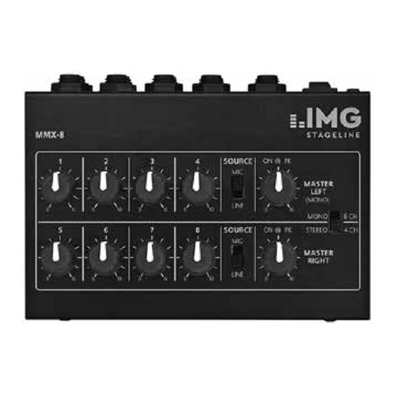
MMX-8 SOURCE MASTER LEFT (MONO) LINE MONO 8 CH STEREO 4 CH SOURCE MASTER RIGHT LINE Miniatur-Audio-Mischer 2 Wichtige Hinweise für den Gebrauch Diese Anleitung richtet sich an Be- Das Gerät entspricht allen relevan- nutzer ohne besondere Fachkennt- ten Richtlinien der EU und ist des- nisse. - Page 5 3 Einsatzmöglichkeiten messer) benötigt. Unbedingt auf die richtige Polung achten: Am Der MMX-8 ist speziell als Vormi- Mittelkontakt muss sich der Plus- scher konzipiert. Es können bis zu pol befinden! acht Mono -Mikrofone oder vier Stereo- Mikrofone angeschlossen Achtung! Wechseln Sie verbrauchte werden.
- Page 6 Die untere Buchse OUTPUT R ist 8) Einzelne Kanäle werden bei Be- nicht in Betrieb. darf mit den entsprechenden Eingangsreglern (1) ein- und 2) Den Umschalter MONO / STEREO ausgeblendet. Das Ausgangssig- (4) auf MONO stellen. nal wird mit dem Summenregler 3) Mit den Umschaltern SOURCE (2) MASTER LEFT (MONO) ein- und die Art der Signalquelle wählen:...
- Page 7 7 Technische Daten RIGHT (3) auf „0“ drehen. Das Gerät mit dem Schalter ON / OFF Eingänge (5) auf der Rückseite einschal- MIC: ..5 mV/ 10 kΩ ten. Die Anzeigen ON PK über LINE: .
-
Page 8: Operating Elements And Connections
MMX-8 SOURCE MASTER LEFT (MONO) LINE MONO 8 CH STEREO 4 CH SOURCE MASTER RIGHT LINE Miniature audio mixer 2 Important Notes The unit corresponds to all relevant These instructions are intended for directives of the EU and is therefore... -
Page 9: Applications
3 Applications serve the correct polarity: The positive pole must be at the cen- The MMX-8 has especially been de- tre contact! signed as a pre-mixer and allows Attention! Replace exhausted bat- connection of up to eight mono teries in time and remove the bat-... - Page 10 3) Select the type of signal source 6 Stereo Operation with selector switches In stereo operation up to 4 stereo SOURCE (2): signal sources may be connected to the inputs (8). The left channels are MIC = microphone always connected to the upper jack LINE = l ine input (tuner, CD, and the right channels to the lower cassette)
- Page 11 6) Adjust the output level with 7 Specifications the controls MASTER LEFT and Inputs MASTER RIGHT so that the fol- MIC: ..5 mV/10 kΩ lowing unit is adjusted to an LINE: .
-
Page 12: Eléments Et Branchements
MMX-8 SOURCE MASTER LEFT (MONO) LINE MONO 8 CH SOURCE STEREO 4 CH MASTER RIGHT LINE Table de mixage miniature audio 2 Conseils importants d’utilisation Cette notice s’adresse aux utilisa- L’appareil répond à toutes les direc- teurs sans connaissances techniques tives nécessaires de l’Union euro-... -
Page 13: Possibilités D'utilisation
Une fiche basse tension 5,5 / 2,1 mm (diamètre ex- 3 Possibilités d’utilisation térieur / intérieur) est nécessaire. La MMX-8 est tout particulièrement Veillez à respecter la polarité : conçue pour servir de prémixage. le pôle plus doit se trouver au Vous pouvez relier 8 micros mono contact médian. -
Page 14: Mode Stereo
gistreur. Si vous reliez des micros de sortie avec le potentiomètre à la table, il faut relier la table à MASTER LEFT (MONO). l’entrée micro de l’amplificateur 8) Les potentiomètres d’entrée (1) ou de l’enregistreur. La prise in- permettent de faire entrer et férieure OUTPUT R est hors de sortir des canaux individuels, si service. -
Page 15: Master Left Et Master Right
au-dessus potentiomètres 7 Caractéristiques techniques s’allument brièvement unique- Entrées ment avec une luminosité maxi- MIC : ..5 mV/10 kΩ male puis avec une luminosité LINE : ..50 mV/ 20 kΩ plus faible. -
Page 16: Elementi Di Comando E Collegamenti
MMX-8 SOURCE MASTER LEFT (MONO) LINE MONO 8 CH SOURCE STEREO 4 CH MASTER RIGHT LINE Mixer audio mini universale 2 Avvertenze importante per l’uso Queste istruzioni sono rivolte a utenti senza conoscenze tecniche L’apparecchio è conforme a tutte le specifiche. Vi preghiamo di leggerle direttive rilevanti dell’UE e pertanto... - Page 17 5,5 / 2,1 mm (diametro esterno / in- claggio. terno). Rispettare assolutamente la corretta polarità: sul contatto 3 Possibilità d’impiego centrale si deve trovare il polo MMX-8 è stato concepito special- positivo! mente come premixer. Si possono Attenzione! Sostituire tempesti-...
- Page 18 stesso deve essere collegato con 8) Per singoli canali, le dissolvenze l’ingresso microfono dell’ampli- sono possibili mediante i regola- ficatore o del registratore. La tori di ingresso (1). Per le dissol- presa inferiore OUTPUT R è di- venze del segnale di uscita ci si sattivata.
- Page 19 7 Dati tecnici mente con luminosità massima e rimangono quindi accese con Ingressi luminosità minore. MIC: ..5 mV/10 kΩ 5) Posizionare sullo “0” i regola- LINE: ..50 mV/ 20 kΩ tori di ingresso (1) dei canali non Uscite:.
- Page 20 MONACOR INTERNATIONAL GmbH & Co. KG • Zum Falsch 36 • 28307 Bremen • Germany Copyright by MONACOR INTERNATIONAL. All rights reserved. A-0980.99.04.02.2016 ©...


