Publicité
Les langues disponibles
Les langues disponibles
Liens rapides
Smart-RTC
RT Econ U
RT Econ A
RTH Econ U
RTH Econ A
Raumtemperatur-
Regler zum
Anschluss an den
Wärmepumpen-
manager (RTH mit
Feuchtefühler)
Bestell-Nr. / Order no. / N°de commande : 452114.66.73
Room
temperature
controller for
connection to the
heat pump
manager (RTH
with humidity
sensor)
Montage- und
Gebrauchsanweisung
Installation and
Operating Instructions
Instructions d'installation et
d'utilisation
Régulateur de
température
ambiante à
raccorder au
gestionnaire de
pompe à chaleur
(RTH avec sonde
d'humidité)
FD 9408
Publicité
Chapitres

Manuels Connexes pour Dimplex Smart-RTC RT Econ U


Sommaire des Matières pour Dimplex Smart-RTC RT Econ U
- Page 1 Smart-RTC Montage- und RT Econ U Gebrauchsanweisung RT Econ A Installation and RTH Econ U Operating Instructions RTH Econ A Instructions d’installation et d’utilisation Raumtemperatur- Room Régulateur de Regler zum temperature température Anschluss an den controller for ambiante à Wärmepumpen- connection to the raccorder au manager (RTH mit...
-
Page 3: Table Des Matières
Smart-RTC Inhaltsverzeichnis Bitte sofort lesen ........................DE-2 1.1 Wichtige Hinweise ..........................DE-2 1.2 Bestimmungsgemäßer Gebrauch......................DE-2 1.3 Gesetzliche Vorschriften und Richtlinien ..................... DE-2 Allgemein ............................ DE-2 Lieferumfang..........................DE-3 3.1 RT(H) Econ U ............................DE-3 3.2 RT(H) Econ A ............................DE-3 Montage............................ -
Page 4: Bitte Sofort Lesen
Smart-RTC Bitte sofort lesen 1.1 Wichtige Hinweise ACHTUNG! ACHTUNG! Bei der Inbetriebnahme sind die länderspezifischen sowie die einschlägi- Zur Gewährleistung der Frostschutzfunktion darf der Wärmepumpen- gen VDE-Sicherheitsbestimmungen, insbesondere VDE0100 und die manager und die Erweiterungsmodule nicht spannungsfrei geschaltet Technischen Anschlussbedingungen der Energieversorgungsunter- werden. -
Page 5: Lieferumfang
Smart-RTC Lieferumfang 3.1 RT(H) Econ U 3.2 RT(H) Econ A Lieferumfang: Lieferumfang: Smart-RTC für Unterputzmontage Smart-RTC für Aufputzmontage 2 Schrauben zur Befestigung in der Unterputzdose 2 Schrauben und 2 Dübel für die Wandmontage Montage- und Gebrauchsanweisung ... -
Page 6: Montage Rt(H) Econ A
Smart-RTC 4.3 Montage RT(H) Econ A Der RT(H) Econ A wird direkt auf die Oberfläche der Wand mon- muss die Schraube A3 gelöst werden. Jetzt die Halterung ent- tiert. (Geräte-Abmessungen siehe Anhang Kap. 2.2 .) sprechend der Einbaulage drehen und mit der Schraube A3 wie- der befestigen. -
Page 7: Elektrischer Anschluss
Smart-RTC 4.4 Elektrischer Anschluss ACHTUNG! Elektrische Installationsarbeiten dürfen nur von einer Elektrofachkraft durchgeführt werden. Vor den elektrischen Anschlussarbeiten auf Span- nungsfreiheit prüfen. 4.4.1 Stromversorgung Der Anschluss der Stromversorgung des Geräts erfolgt über ein bauseits zu erstellendes 2-adriges Kabel an den Klemmen L und N (1~ /N, 230 V, 50 Hz). -
Page 8: Inbetriebnahme
Smart-RTC Inbetriebnahme HINWEIS lungen die Regelung auf Raumtemperatur (Einstellungen - 1. Heizkreis - Regelung über Raumtemperatur) und anschließend Damit die Kommunikation zwischen Wärmepumpenmanager und Smart- der Temperaturfühler auf Smart-RTC gestellt werden (Einstellun- ordnungsgemäß gestartet wird, muss einmalig gen - 1.Heizkreis - Temperaturfühler). Wärmepumpenmanager und am Smart-RTC ein Neustart durch Abschalten der Spannungsversorgung durchgeführt werden. -
Page 9: Funktionsbeschreibung
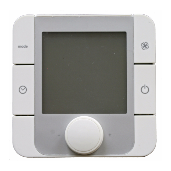
Smart-RTC Funktionsbeschreibung Abb. 5.1: Beschreibung der Tastenfunktion Abb. 5.2: Beschreibung der Displayanzeige Dreh-Druck-Knopf „Sollwerteinstellung“: Wahltaste „Schnellheizen“: durch Drehen der Taste wird die Solltemperatur einge- Die Raumregelung wird außer Kraft gesetzt. Als Rück- stellt. Der Sollwert wird „automatisch nach 3 Sekunden lauf-Soll-Temperatur wird die am Wärmepumpenmana- übernommen. - Page 10 Smart-RTC DE-8 452114.66.73 · FD 9408...
- Page 11 Smart-RTC Table of contents Please read immediately......................EN-2 1.1 Important information........................... EN-2 1.2 Intended use ............................EN-2 1.3 Legal regulations and directives ......................EN-2 General ............................EN-2 Scope of supply.......................... EN-3 3.1 RT(H) Econ U ............................EN-3 3.2 RT(H) Econ A ............................EN-3 Installation ..........................
-
Page 12: Please Read Immediately
Smart-RTC 1 Please read immediately 1.1 Important information ATTENTION! ATTENTION! During start-up, observe the respective national safety regulations and To ensure that the frost protection function works properly, the heat the applicable VDE safety regulations, particularly VDE0100, as well as pump manager and the extension modules must remain connected to the the technical connection requirements of the utility company (EVU) and power supply at all times. -
Page 13: Scope Of Supply
Smart-RTC 3 Scope of supply 3.1 RT(H) Econ U 3.2 RT(H) Econ A Scope of supply: Scope of supply: Smart-RTC for flush mounting Smart-RTC for surface mounting 2 screws for mounting in a flush-type box 2 screws and 2 dowels for wall mounting ... -
Page 14: Rt(H) Econ A Installation
Smart-RTC 4.3 RT(H) Econ A installation The RT(H) Econ A is mounted directly onto the wall surface. position for the display to be obtained. After loosening the scerw, (Device dimensions see Appendix chapter 2.2 .) rotate the mounting into the correct position, and re-mount with screw A3. -
Page 15: Electrical Connection
Smart-RTC 4.4 Electrical connection ATTENTION! Work must only be carried out by qualified personnel. Before carrying out any work, always ensure that there is no voltage present at the terminals. 4.4.1 Power supply The power supply is connected to terminals L and N (1~ /N, 230 V, 50 Hz) of the device via a 2-core cable (to be provided by the customer). -
Page 16: Start-Up
Smart-RTC Start-up NOTE to room temperature (Settings - Heating circuit 1 - Room temperature regulation) and the temperature sensor must then To start proper communication between the heat pump manager and the be set to Smart-RTC (Settings - Heating circuit 1 - Temperature Smart-RTC, the heat pump manager and the Smart-RTC must both be sensor). -
Page 17: Functional Description
Smart-RTC 5 Functional description Fig. 5.1: Description of the key functions Fig. 5.2: Description of the display "Set value setting" rotary pushbutton: "Rapid heating" selector button: Turn the button the set the set temperature. The set value ... - Page 18 Smart-RTC EN-8 452114.66.73 · FD 9408...
- Page 19 Smart-RTC Table des matières À lire immédiatement ......................... FR-2 1.1 Remarques importantes ........................FR-2 1.2 Utilisation conforme ..........................FR-2 1.3 Prescriptions et normes légales......................FR-2 Généralités..........................FR-2 Matériel fourni..........................FR-3 3.1 RT(H) Econ U ............................FR-3 3.2 RT(H) Econ A ............................FR-3 Montage............................FR-3 4.1 Généralités ............................FR-3 4.2 Montage du régulateur RT(H) Econ U ....................FR-3 4.3 Montage du régulateur RT(H) Econ A ....................FR-4 4.4 Branchements électriques ........................FR-5...
-
Page 20: Lire Immédiatement
Smart-RTC 1 À lire immédiatement 1.1 Remarques importantes ATTENTION ! ATTENTION ! Avant de mettre en service le régulateur, respecter les consignes de Pour assurer la fonction antigel, le gestionnaire de pompe à chaleur et les sécurité en vigueur dans le pays, les dispositions de sécurité afférentes modules d’extension ne doivent pas être commutés hors tension. -
Page 21: Matériel Fourni
Smart-RTC 3 Matériel fourni 3.1 RT(H) Econ U 3.2 RT(H) Econ A Matériel fourni Matériel fourni Smart-RTC pour un montage encastré Smart-RTC pour un montage en saillie 2 vis permettant de fixer le régulateur au boîtier encastré ... -
Page 22: Montage Du Régulateur Rt(H) Econ A
Smart-RTC 4.3 Montage du régulateur RT(H) Econ A Le régulateur RT(H) Econ A est fixé directement en surface de alors le support en fonction de la position de montage et le fixer paroi (voir les dimensions du régulateur voir Annexe Chap. 2.2 ). définitivement en serrant la vis A3. -
Page 23: Branchements Électriques
Smart-RTC 4.4 Branchements électriques ATTENTION ! Seul un spécialiste électricien est habilité à effectuer les travaux de montage électrique. Vérifier l’absence de tension avant de commencer les travaux. 4.4.1 Cordon d’alimentation électrique Un câble 2 brins fourni par le client et raccordé aux bornes L und N (1~ /N, 230 V, 50 Hz) assure l’alimentation électrique du régulateur. -
Page 24: Mise En Service
Smart-RTC Mise en service REMARQUE « Réglages » du menu « Chauffagiste » (Réglages - 1er circuit de chauffage - Régulation via température ambiante), puis sur Pour que la communication entre le gestionnaire de pompe à chaleur et le « Smart-RTC » au point « Sonde de température » (Réglages - régulateur Smart-RTC puisse démarrer correctement, il convient 1er circuit de chauffage - Sonde de température). -
Page 25: Fonctionnement
Smart-RTC 5 Fonctionnement Fig. 5.1: Description du fonctionnement des boutons sélecteurs Fig. 5.2: Description de l’écran d’affichage Sélecteur rotatif à poussoir « Réglage de la température Bouton sélecteur « Chauffage rapide » de consigne » Le régulateur de la température ambiante est court- ... - Page 26 Smart-RTC FR-8 452114.66.73 · FD 9408...
-
Page 27: Anhang / Appendix / Annexes
Smart-RTC Anhang / Appendix / Annexes Technische Geräteinformationen / Technical Device Information / Informations techniques sur les appareils ................A-II Abmessung / Dimensions / Dimensions ................... A-III 2.1 RT Econ U / RTH Econ U ........................A-III 2.2 RT Econ A / RTH Econ A ........................A-III 452114.66.73 ·... -
Page 28: Technische Geräteinformationen / Technical Device Information / Informations Techniques Sur Les Appareils
Smart-RTC 1 Technische Geräteinformationen / Technical Device Information / Informations techniques sur les appareils Netzspannung / Supply voltage / Tension secteur 230 V AC 50 Hz Spannungsbereich / Voltage range / Plage de tension 195 bis / to / à 253 V AC Leistungsaufnahme / Power consumption / Puissance absorbée 2 VA Schutzart nach EN 60529 /... -
Page 29: Abmessung / Dimensions / Dimensions
Smart-RTC 2 Abmessung / Dimensions / Dimensions 2.1 RT Econ U / RTH Econ U 2.2 RT Econ A / RTH Econ A 452114.66.73 · FD 9408 A-III... - Page 30 Smart-RTC A-IV 452114.66.73 · FD 9408...
- Page 31 Smart-RTC 452114.66.73 · FD 9408...
- Page 32 Garantiebedingungen Kundendienstadresse siehe Irrtümer und Änderungen vorbehalten. Montage- und Gebrauchsanweisung Wärmepumpe. Subject to alterations and errors. For the terms of the guarantee and after-sales service Sous réserve d’erreurs et modifications. addresses, please refer to the Installation and Operating Instructions for Heat Pumps. Pour les conditions de garantie et les adresses SAV, se référer aux instructions de montage et d’utilisation de la pompe à...