Table des Matières
Publicité
Les langues disponibles
Les langues disponibles
Liens rapides
Publicité
Chapitres
Table des Matières
Dépannage

Sommaire des Matières pour RocHobby 1941 MB Scaler
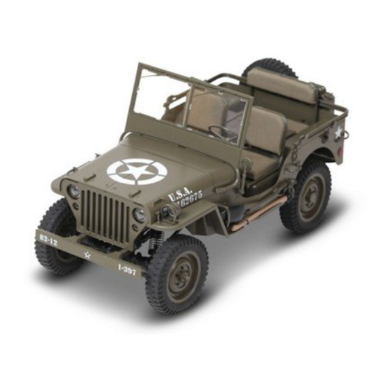
- Page 1 1:6 1941 mb scaler Instruction Manual Bedienungsanleitung Manuel d’utilisation PNP version does not include transmitter and receiver . 操作手册 PARAMETERS Length:530.5mm Height:270mm Ground clearance: 39.5mm Departure angle: 22° Width: 258mm Wheelbase: 324mm Approach angle: 58° Breakover angle: 36°...
-
Page 3: Table Des Matières
TABLE OF CONTENTS ............... Safety precautions ..............Radio system manual ............... ESC system manual ................Vehicle setup ........Wiper installation,Lifting and retracting the windshield ................ Opening the hood ............Setting up the canvas bracket ..............Operating the vehicle ............Front and rear wheel assembly ............... -
Page 4: Safety Precautions
SAFETY PRECAUTIONS Introduction This model is a sophisticated hobby product and not a toy. It must be operated using caution and common sense. Beginners should seek the advice of experienced hobbyists to ensure that the model is properly built, run and maintained. Some mechanical knowledge and ability is expected of the hobbyist, as failure to operate and maintain this model may result in property damage, serious injury or even death. -
Page 5: Radio System Manual
Please read this manual carefully prior to using.We are not responsible for any intention- al damage or improper use.lf you require any additional information or have any quesions adout he product or its use,please contact us via(www.rochobby.com). This product is not a toy! (14+) Recommended for ages 14 and up. Adult supervision MADE IN CHINA required for ages under 18 years old. - Page 6 Warranty The ROCHOBBY 4 channel radio system is guaranteed to be free from defects in materials and workmanship within 30 days of the purchase of the product. If the product has been mishandled, abused, used incorrectly or used for an application other than its intended purpose- ROCHOBBY is not liable for any loss or damage, whether direct or indirect, incidental or conse- quential, or from any special situatuon, arising from the use, misuse, or abuse of this product.
-
Page 7: Battery Installation
Removing or replacing the handle 1.Pull the handle release latch. 2.Pull back on the handle to release the handle from the transmitter itself. 3.To replace the handle, pull back on the handle release latch and push the handle back onto the transmitter. Battery installation This transmitter accepts alkaline or NiMH AA batteries. - Page 8 Channel connection Channel 1: Controlled by the wheel, connect to a servo for steering. • Channel 2: Controlled by the trigger, connect to the ESC or a servo for throttle/brake. • • Channel 3: Controlled by the adjustment knob (0-100%) for optional use. This port can also be used to connect a transpon- der device used in racing.
-
Page 9: Esc System Manual
LED> 4CH 2.4GHz W A T E R P R O O F R E C E I V E R SW> LED> 4CH 2.4GHz W A T E R P R O O F R E C E I V E R SW>... - Page 10 Specifications WP-1060-BRUSHED Model Cont. / Burst Current Forward: 60A / 360A Backward: 30A / 180A Input 2-3S Lipo, 5-9 Cells NiMH Vehicles applicable 1:10 on-road, off-road Buggy, Truggy, SCT 1:10 Crawlers, Tank &Boat 2S Lipo or 5-6 cells NiMH 540 or 550 size motor ≥ 8T or RPM <45000 @7.2V Motor Limit 3S Lipo or 7-9 cells NiMH 540 or 550 size motor ≥13T or RPM <30000 @7.2V...
- Page 11 3. Throttle Range Setting (Throttle Range Calibration) In order to make the ESC match the throttle range of different transmitters, the calibrationof the ESC is necessary. To calibrate the ESC, please turn on the transmitter, keep throttle stick at its neutral position, wait for 3 seconds to let the ESC execute self-test and automatic throttle calibration.
-
Page 12: Protection Functions
Protection functions 1. Low voltage Cut-off (LVC) protection: If the voltage of battery pack is lower than the threshold for 2 seconds, the ESC will enter the protection mode. When the car stops, the red LED blinks to indicate the low voltage cut-off protection has been activated. Table A: LVC protection for WP-1060-BRUSHED 2S Lipo 3S Lipo... -
Page 13: Vehicle Setup
Fault Possible Reason Drivetrain fault Solution Check the transmitter and the receiver. The throttle signal is lost. Check the throttle wire connection. The motor suddenly stops running while in working state. Low voltage cut-off protection or Replace the battery pack, or cool Over-heat cut-off protection has down the ESC. -
Page 14: Wiper Installation,Lifting And Retracting The Windshield
WIPER INSTALLATION,LIFTING AND RETRACTING THE WINDSHIELD Install the windshield wipers by referencing the diagram below. Step1: Please install the wipers in the diagram2 position. Step2: Lift the windshield assembly. Step3: Gently press on the center of the windshield, the component will bend and lock onto the hood. Pressing on the center of the windshield again will allow for the windshield to be retracted. -
Page 15: Setting Up The Canvas Bracket
SETTING UP THE CANVAS BRACKET Step1: Pull out the canvas bracket. Step2: Insert the canvas bracket into the bracket mount. OPERATING THE VEHICLE Step 1: Turn on the transmitter- the status LED will turn blue and an audible tone will be emitted. Step 2: Power on the vehicle by turning on the ESC switch. - Page 16 TABLE OF CONTENTS ............... Sicherheitshinweise ............Bedienungsanleitung Fernsteuerung ..........Bedienungsanleitung Fahrtenregler (ESC) ................Setup Fahrzeug ............Demontage der Windschutzscheibe ..............Öffnen der Motorhaube ............Montage des Verdeckgestänges ..............Betrieb des Fahrzeuges ........Explosionszeichnung der Vorder- und Hinterräder ............ Explosionszeichnung der Vorderachse ...........
-
Page 17: Sicherheitshinweise
SICHERHEITSHINWEISE Introduction This model is a sophisticated hobby product and not a toy. It must be operated using caution and common sense. Beginners should seek the advice of experienced hobbyists to ensure that the model is properly built, run and maintained. Some mechanical knowledge and ability is expected of the hobbyist, as failure to operate and maintain this model may result in property damage, serious injury or even death. -
Page 18: Bedienungsanleitung Fernsteuerung
Please read this manual carefully prior to using.We are not responsible for any intention- al damage or improper use.lf you require any additional information or have any quesions adout he product or its use,please contact us via(www.rochobby.com). This product is not a toy! (14+) Recommended for ages 14 and up. Adult supervision MADE IN CHINA required for ages under 18 years old. -
Page 19: Die Funktionen Im Überblick
Warranty The ROCHOBBY 4 channel radio system is guaranteed to be free from defects in materials and workmanship within 30 days of the purchase of the product. If the product has been mishandled, abused, used incorrectly or used for an application other than its intended purpose- ROCHOBBY is not liable for any loss or damage, whether direct or indirect, incidental or conse- quential, or from any special situatuon, arising from the use, misuse, or abuse of this product. - Page 20 Entfernen des Handgriffes 1. Drücken Sie die Öffnungslasche. 2. Ziehen Sie den Griff von dem Oberteil der Fernsteuer- ung nach hinten. 3. Um den Griff wieder einzusetzen drücken Sie bitte erneut die Öffnungslasche runter und schieben den Griff wieder in das Oberteil der Fensteuerung. Einsetzen der Batterien in die Fernsteuerung.
-
Page 21: Binden Von Sender Und Empfänger
Anschluss der Steuerkanäle Kanal 1: Wird durch das Lenkrad kontrolliert. Schließen Sie hier bitte das Lenkservo an. • Kanal 2: Wir durch den Gashebel kontrolliert. Schließen Sie hier einen Fahrtregler (ESC) oder ein Servo für Gas / Bremse an. • •... -
Page 22: Bedienungsanleitung Fahrtenregler (Esc)
LED> 4CH 2.4GHz W A T E R P R O O F R E C E I V E R SW> LED> 4CH 2.4GHz W A T E R P R O O F R E C E I V E R SW>... - Page 23 Spezifikationen WP-1060-BRUSHED Model Kont - / Spitzenspannung Vorwärts: 60A / 360A Rückwärts: 30A / 180A Eingang 2-3S Lipo, 5-9 Cells NiMH Geeignete Fahrzeuge 1:10 On-Road,Off-Road Buggy,Truggy,SCT 1:10 Crawler, Panzer &Boot 2S Lipo oder 5-6 Zellen NiMH 540 oder 550 Größe Motor Motor ≥ 8T or RPM <45000 @7.2V Motor Limit 3S Lipo oder 7-9 Zellen NiMH 540 oder 550 Größe Motor ≥13T or RPM <30000 @7.2V...
- Page 24 3. Einstellung des Gasweges (Kalibrierung) Damit der Fahrtenregler (ESC) mit verschiedenen Fernsteuerungen betrieben werden kann, ist eine Kalbrierung des Reglers notwendig. Um den Regler zu kalibrieren, schalten Sie den Sender ein und halten dabei den Gashebel in neutraler Postion. Warten Sie für drei Sekunden, der Regler führt in dieser Zeit einen Selbsttest und eine automatische Kalibrierung durch.
-
Page 25: Mögliche Ursache
Schutzfunktionen 1. Niederspannungsabschaltung (LVC): Erreicht die Akkuspannung den eingestellten Grenzwert länger als für 2 Sekunden wechselt der Regler in den Protection Mode. Das Fahrzeug stoppt und die rote LED zeigt blinkend an, dass die Niederspannungsabschaltung aktiviert wurde. Abbildung A: LVC Protection für WP-1060-BRUSHED 2S Lipo 3S Lipo Die Leistung wird auf 50% bei 6,5 V Span-... -
Page 26: Anschluss Des Akkus
Problem Mögliche Ursache Lösung Prüfen Sie die Fernsteuerung und Verlust des Fernsteuersignals Empfänger. Prüfen Sie die Kabel- verbindung des Gaskanals Der Motor stoppt plötzlich bei dem Betrieb. Aktivierung des Niederspannungs- Ersetzen Sie den Akku oder lassen oder Überhitzsschutz. den Fahrtenregler abkühlen. Prüfen Sie die Einstellungen Stellen Sie D/R,EPA,ATL auf 100% Das Fahrzeug erreicht nicht die... -
Page 27: Öffnen Der Motorhaube
WISCHER EINBAUEN,HEBEN UND LÖSEN DER WINDSCHUTZSCHEIBE Installieren der Scheibenwischer durch Bezugnahme auf die folgende Diagramm. Schritt1: Bitte installieren Sie die Scheibenwischer in der Position in Diagramm 2. Schritt2: Heben sie die Windschutzscheibe an. Schritt3: Drücken sie vorsichtig auf die Mitte der Scheibe bis auf der Haube einrastet. -
Page 28: Montage Des Verdeckgestänges
MONTAGE DES VERDECKGESTÄNGES Schritt 1: Ziehen sie das Gestänge aus der Halterung. Schritt 2. Setzen sie das Gestänge wie abgebildet in die hinteren Halter ein. BETRIEB DES FAHRZEUGES Schritt 1: Schalten Sie den Sender, die Status LED leuchtet blau und ein Ton ertönt. Schritt 2: Schalten Sie das Fahrzeug mit dem Schalter am Fahrtenregler ein. - Page 29 TABLE DES MATIÈRES ..............Consignes de sécurité ..........Manuel de l'ensemble de radiocommande ..........Manuel du variateur électronique de vitesse ..............Préparation du véhicule ........Installer l'essuie-glace,Monter ou plier le pare-brise ............... Ouverture du capot ............Mise en place du support de capote ..............
-
Page 30: Consignes De Sécurité
CONSIGNES DE SÉCURITÉ Introduction This model is a sophisticated hobby product and not a toy. It must be operated using caution and common sense. Beginners should seek the advice of experienced hobbyists to ensure that the model is properly built, run and maintained. Some mechanical knowledge and ability is expected of the hobbyist, as failure to operate and maintain this model may result in property damage, serious injury or even death. -
Page 31: Manuel De L'ensemble De Radiocommande
Please read this manual carefully prior to using.We are not responsible for any intention- al damage or improper use.lf you require any additional information or have any quesions adout he product or its use,please contact us via(www.rochobby.com). This product is not a toy! (14+) Recommended for ages 14 and up. Adult supervision MADE IN CHINA required for ages under 18 years old. -
Page 32: Garantie
Garantie L'ensemble radio 4 voies ROCHOBBY est garanti contre les défauts de fabrication et d’assemblage pour une période de 30 jours à compter de la date de l’achat. Si le produit a été mal manipulé, mal utilisé, utilisé de manière incorrecte ou utilisé pour une application autre que sa destination, ROCHOBBY n'est pas responsable de toute perte ou dommage, direct ou indirect, accidentel ou consécutif, ou de toute situation particulière, résultant de l'utilisation, d'une mauvaise utilisation ou abus de ce... -
Page 33: Dépose Et Remise En Place De La Poignée
Dépose et remise en place de la poignée 1.Tirez le verrou de maintien de la poignée. 2.Tirez la poignée en arrière pour la sortir de l'émetteur proprement dit. 3.Pour remettre la poignée en place, tirez le verrou en arrière et poussez la poignée contre l'émetteur. Mise en place des piles ou batteries Cet émetteur accepte des piles alcalines ou des batteries NiMH au format AA. -
Page 34: Installation Et Connexion Du Récepteur
Correspondance des voies Voie 1 : Contrôlée par le volant, se connecte au servo de direction. • Voie 2 : Contrôlée par la gâchette, se connecte au variateur ou à un servo de gaz. • • Voie 3 : Contrôlée par le potentiomètre de réglage (0 à 100 %), pour utiliser une option. Ce port peut aussi servir à connect- er un transpondeur utilisé... -
Page 35: Utilisation
LED> 4CH 2.4GHz W A T E R P R O O F R E C E I V E R SW> LED> 4CH 2.4GHz W A T E R P R O O F R E C E I V E R SW>... -
Page 36: Réglage Du Variateur
Caractéristiques WP-1060-BRUSHED Modèle Courant max Constant / En pointe Marche AV : 60 A / 360 A Marche Arrière : 30 A / 180 A Alimentation LiPo 2S-3S, ou 5 à 9 éléments NiMH Type de véhicules utilisables Piste, Buggy tout terrain, Truggy 1/10 - Crawlers 1/10 - Chars - Bateaux LiPo 2S ou NiMH 5-6 elts Moteur format 540 ou 550 ≥... -
Page 37: Positions Du Manche (Gâchette) Des Gaz
3. Calibrage de la plage des gaz Afin de faire correspondre le variateur avec la plage des gaz de différents émetteurs, il est nécessaire de calibrer le varia- teur. Pour calibrer le variateur, allumez l'émetteur, laissez la gâchette des gaz (ou le manche de gaz) en position neutre. Attendez 3 secondes que le variateur réalise un auto-test de calibrage des gaz. -
Page 38: Fonctions De Protection
Fonctions de protection 1. Protection de tension faible (LVC) : Si la tension du pack d'accus est inférieure au seuil durant 2 secondes, le variateur entre en mode de protection. Quand la voiture s'arrête, la LED rouge clignote pour indiquer que la protection contre la sous-tension s'est activée. Tableau A : Protection LVC du WP-1060-BRUSHED LiPo 2S LiPo 3S... -
Page 39: Solution De Dépannage
Défaut Raison probable Solution de dépannage Vérifiez émetteur et récepteur. Perte du signal des gaz. Vérifiez les fils de connexion des gaz. Le moteur s'arrête soudainement alors qu'il est en état de marche. Remplacez l'accu, ou laissez refroidir Activation de la protection de tension le variateur. -
Page 40: Installer L'essuie-Glace,Monter Ou Plier Le Pare-Brise
INSTALLER L'ESSUIE-GLACE,MONTER OU PLIER LE PARE-BRISE Installez les essuie-glaces en faisant référence au schéma ci-dessous. ETAPE 1 : Veuillez installer les essuie-glaces dans la position du diagramme 2. ETAPE 2 : Soulevez l'ensemble du pare-brise. ETAPE 3 : Poussez doucement au centre du pare-brise, l'élément se plie et se verrouille sur le capot. -
Page 41: Mise En Place Du Support De Capote
MISE EN PLACE DU SUPPORT DE CAPOTE ETAPE 1 : Tirez le support de capote. ETAPE 2 : Insérez le support de capote dans ses supports. UTILISATION DU VÉHICULE ETAPE 1 : Allumez l'émetteur. La LED d'état doit s'allumer en bleu et un signal sonore doit être émis. ETAPE 2 : Mettez le véhicule sous tension avec l'inter du variateur. - Page 42 目录 ................安全保障措施 ................无线电系统手册 ................电调系统手册 ................遥控车设置 ............安装雨刷, 提起/收放挡风玻璃窗框 ................打开引擎盖 ................ 设置帆布车篷支架 ................遥控车操作说明 ................前轮和后轮装配 .................. 前桥装配 ................油式避震器装配 ................驱动牙箱组装配 .................. 后桥装配 ................中传动牙箱装配 ................车壳装配一 ................车壳装配二 ................车壳装配三 ................车底盘爆炸图 ................配件表明细一 ................
- Page 43 安全保障措施 指引 这模型是一个竞赛爱好者产品,而不是玩具。 它必须谨慎使用。 初学者应寻求有经验的爱好者的指导去进行,以确保模型得 到正当的组装、运行及维护。 期望业余爱好者有一些机械知识和能力,因为未能操作和维护该模型产品可能导致财产损坏及严重伤害或导致死亡。 没有适当的成人监督下,这模型不适合儿童独自使用。 请细阅本手册中的说明和所有张贴的警告,以便正确地组装、设置、使 用和维护此模型。 安全、预防措施及警告 这个模型是由一个无线电信号控制的,它会受到来自你控制以外许多源的干扰。 这种干扰会造成短暂的控制失误, 所以在您的模型周围的所有方向, 请必要保持一个安全的距离, 因为这将有助于避免产品碰撞或损坏。 请远离汽车、交通或人员的区域,操作您的模型。 • 不要用电量过低的电池在遥控器上操作你的模型。 • 仔细遵循本产品和任何可选的支持设备(如充电器、充电电池组等)的指示和警告。 • 保持所有零件,化学溶剂,油类及电器元件不让儿童接触到。 • 湿气可能会随着时间的推移对电子元件造成损害。 请确保所有电子元件,甚至防水元件,在每次运行后都保持干燥。 千万 • 不要在盐水中运行本模型。 无线电系统装置 使用前请仔细阅读本手册。 我们不对任何故意损坏或不当使用负责。 这个产品不是玩具!! 建议 在 14 岁及以上者使用。 18 岁以下的 , 需接受成年人监督下使用。 本产品部分包含小零件,请保持 3 岁及更小的儿童无法接触本产品。...
- Page 44 无线电系统装置 警吿 洛克模型保证 4 频道无线电系统在产品购买后 30 天内无材料和工艺缺陷。 如果产品被错误地处理、 滥用、 不正确地使用或用于 预期用途以外的应用 - 洛克模型將不对该使用、 滥用本产品而引起的任何损失或损害及无论是直接或间接、 附带或间接的损失或 损害的任何特殊而作出赔偿。 功能操作介绍 6. 遥控器手绳板机 7. CH3-EPA+/- 8. CH4-EPA+/- 9. 电池箱:4x AA 电池 10. 频道 3 按键 11. 二极发光灯 12. 反向: 1:转动并保持方向盘向左或右,同时按下 Rev 按钮。 发 出一个声响后, 转向通道将被反转。 2:在同时按下...
- Page 45 拆卸或更换手柄 1. 拉动手柄释放闩锁。 2. 拉回手柄, 从遥控器本身释放手柄。 3. 若要更换手柄,请拉回手柄释放锁存器,并将手柄推回 遥控器。 电池安装 此遥控器接受碱性或 NiMHAA 电池。 有内置的低压报警, 当电压低于 4.5V/-0.2 时, 蜂鸣器将连续发声, LED 灯将闪烁。 这是为 了提醒用户更换新的电池。 1. 从遥控器上拆下电池盖。 2. 根据电池支架上的极性标记插入 4 个新的 AA 电池。 3. 重新安装电池盖 警告:不要试图给不可充电的电池充电, 可能会引起爆炸。 警告:请不要反装电池, 否则会破坏电路板功能。...
- Page 46 通道连接 • 通道 1:控制车轮, 连接到伺服转向。 • 通道 2:控制扣机, 连接到 ESC 或伺服油门 / 刹车。 • 通道 3:控制调节旋钮 (0-100%) , 可供选择使用。 此端口还可用于连接用于赛车的应答器设备。 • AUX (通道 4):控制按钮 ( 打开 / 关闭) , 可供选择使用。 这个端口是最常用的 LED 灯套件。 使用此端口连接外部电池, 用于燃 气车辆。 接收器安装及连接 安装 为了实现您的无线电系统的全工作范围, 重要的是接收器天线没有损坏和安装正确。 它应该安装尽可能天线垂直的位置。 天线的 末端应包含在天线管内。...
- Page 47 LED> 4CH 2.4GHz W A T E R P R O O F R E C E I V E R SW> LED> 4CH 2.4GHz W A T E R P R O O F R E C E I V E R SW>...
- Page 48 规格 WP-1060-BRUSHED 型号 持续 / 迅间电流 前进:60A/360A 后退:30A/180A 输入 2-3S 锂电或 5-9 芯镍氢电 适用的车辆 1:10 平路车, 越野车, 货卡, 短卡 , 1:10 攀爬车, 坦克和船 2S 锂电或 5-6 芯镍氢电 540 或 550 电机≥8T 或 RPM <45000@7.2V 电机限制 3S 锂电或 7-9 芯镍氢电 540 或 550 电机≥13T 或 RPM <30000@7.2V 阻抗...
- Page 49 3. 油门范围设定 (油门范围校正) 为了使 ESC 与不同遥控器油门范围相匹配, 需要对 ESC 进行校准。 要校准 ESC, 请打开遥控器, 保持油门棒在其中位, 等待 3 秒让执行自我测试和自动油门校准。 当 ESC 准备运行时, 电机发出一个长的蜂鸣声。 注意 : 当使用新遥控器时请再次校准油门范围中位、 D/R、 ATV、 ATL 或 EPA 的参数, 否则 ESC 可能无法正常工作。 警报声及LED状态 LED状态 警报声表示 一个短蜂鸣声:电池为镍氢/镍镉 • 当油门杆在中性范围内时,红色LED关闭 • 两个短蜂鸣声:电池是2S鋰电 •...
- Page 50 保护功能 1. 低压切断 (LVC) 保护:如果电池组电压低于阈值 2 秒,ESC 将进入保护模式。 当汽车停止时,红色 LED 闪烁表示低压切断 保护已被激活。 图表 A:WP-1060-BRUSHED 的低压保护 2S锂电 3S锂电 当输出 6.5V 降至 50% 到 6.0V 后作切断, 无 当输出 9.75V 降至 50% 到 9.0V 后作切断, 法再恢复运作。 无法再恢复运作。 2. 过热保护:当 ESC 的内部温度高于 100 摄氏度或 212 华氏度 5 秒时, ESC 将减少和切断输出功率。 当汽车停止时,...
- Page 51 故障问题 可能的原因 传动系统故障解决方案 检查发射机和接收器 油门信号丢失 检查油门导线连接情况 电动机在工作状态时突然停止运转 低压切断保护或过热切断保护已启动 更换电池组, 或冷却 ESC 检查设置。 将 D/R、 EPA、 ATL 设置为 100%, 或将 该模型无法达到其最大速度,红色 发射机设置不当 旋钮转到最大值 LED 在全油门下不会变得坚实 将 TRIM 设置为 0 或将旋钮转到其中性 位置 电池的放电能力有限 使用放电能力较好的电池 使用转速较低的电机,或使用较小的小 加速时电机堵塞 电机 RPM 值太高, 齿轮比太激进 齿轮, 以获得较软的齿轮比 汽车的驾驶系统出了问题...
- Page 52 安装雨刷, 提起/收放挡风玻璃窗框 按图指示, 把雨括安装在適当位置。 第一步:请在图示 2 位置安装雨刷。 第二步:提升挡风玻璃组件。 第三步:轻轻按下挡风玻璃的中心, 组件将弯曲并扣在引 擎盖上。 再次按下挡风玻璃的中心弯曲扣位松开收回挡风玻璃。 打开引擎盖 第一步:把引擎盖抬起来。 第二步:将引擎盖支柱移动到发动机舱上, 以保持撑着引擎盖。...
- Page 53 设置帆布车篷支架 第一步:拔出帆布车篷支架。 第二步:将帆布车篷支架插入支架安装中 车辆操作 第一步:打开遥控器 - 状态 LED 将变成蓝色, 并发出可听到的音调。 第二步:打开 ESC 开关给车辆供电。 前面的灯会发光, 发出可听到的声音 在接收器确认遥控器信号已被接收后, 它将发出另一个可听到的音调。 以上指引, 必须安装电池。 本产品带有限滑功能, 如启动动力不足, 请检查限滑片进行更换, 配件:C1067 限滑片。...
- Page 54 (EN)FRONT AND REAR WHEEL ASSEMBLY (DE)EXPLOSIONSZEICHNUNG DER VORDER- UND HINTERRÄDER (FR)MONTAGE DES ROUES AVANT ET ARRIÈRE (CN)前轮和后轮装配 C1002 C1002 C1002 C1002 C1002 C1002/C1041 C1018 C1018 C1003 C1003 C1003 C1003 C1003 C1003/C1042 C1018 C1018...
-
Page 55: Explosionszeichnung Der Vorderachse
(EN)FRONT AXLE ASSEMBLY (DE)EXPLOSIONSZEICHNUNG DER VORDERACHSE (FR)MONTAGE DE L'ESSIEU AVANT (CN)前桥装配 C1013/C1020 C1013/C1023 C1013/C1078 C1013/C1094 C1013/C1082 C1013/C1081 C1013/C1018 C1013/C1025 C1013/C1022 C1013/C1023 C1013/C1018 C1013/C1018 C1013/C1021 C1013/C1018 C1013/C1025 C1013/C1025 C1013/C1070 C1013/C1018 C1013/C1077 C1013/C1022 C1013/C1020 C1013/C1082 C1013/C1082 C1013/C1018 C1013/C1018 C1013/C1023 C1013/C1025 C1013/C1025 C1013/C1018 C1013/C1018 C1013/C1082 C1013/C1022... -
Page 56: Explosionszeichnung Der Stoßdämpfer
(EN)OIL SHOCK ABSORBERS ASSEMBLY (DE)EXPLOSIONSZEICHNUNG DES ÖLDRUCKSTOßDÄMPFERS (FR)MONTAGE DES AMORTISSEURS HYDRAULIQUES (CN)油式避震器装配 C1001/C1075 C1001/C1072 C1001 C1001/C1073 C1001/C1069 C1001 C1001/C1074 C1001 C1001 C1001 C1001 C1001 C1001 C1001/C1065 C1001/C1071 C1001/C1070 (EN)MAIN GEAR BOX ASSEMBLY (DE)EXPLOSIONSZEICHNUNG DER MOTORGETRIEBEBOX (CN)驱动牙箱组装配 (FR)MONTAGE DU RÉDUCTEUR PRINCIPAL C1011 C1011/C1023 C1011/C1076... -
Page 57: Rear Axle Assembly
(EN)REAR AXLE ASSEMBLY (DE)EXPLOSIONSZEICHNUNG DER HINTERACHSE (FR)MONTAGE DE L'ESSIEU ARRIÈRE (CN)后桥装配 C1014/C1020 C1014/C1081 C1014/C1025 C1014/C1018 C1014/C1022 C1014/C1021 C1014/C1018 C1014 C1014/C1025 C1014/C1018 C1014/C1020 C1014/C1025 C1014/C1025 C1014/C1018 C1014/C1023 C1014/C1077 C1014/C1022 C1014/C1018 C1014/C1018 C1014/C1076 C1014/C1094 C1014/C1023 C1014/C1018 C1014/C1023 C1014/C1078 C1014 C1014/C1025 C1014/C1023 C1014/C1023 C1014/C1018 C1014 C1014/C1025... -
Page 58: Transmission Gear Box Assembly
(EN)TRANSMISSION GEAR BOX ASSEMBLY (DE)EXPLOSIONSZEICHNUNG DER GETRIEBEBOX / ACHSABTRIEB (FR)MONTAGE DU BOÎTIER DE TRANSMISSION (CN)中传动牙箱装配 C1012/C1077 C1012/C1022 C1012/C1018 C1012/C1079 C1012/C1078 C1012/C1022 C1012/C1022 C1012/C1023 C1012/C1076 C1012 C1012/C1022 C1012/C1023 C1012 C1012/C1094 C1012 C1012/C1018 C1012/C1023 C1012/C1076 C1012/C1018 C1012/C1022 C1012/C1018 C1012... -
Page 59: Car Body Assembly 1
(EN)CAR BODY ASSEMBLY 1 (DE)EXPLOSIONSZEICHNUNG KAROSSERIE TEIL 1 (FR)MONTAGE DE CARROSSERIE - 1 (CN)车壳装配一 C1018 C1018 C1018 C1081 C1041 C1054 C1054 C1018 C1096 C1054 C1018 C1054 C1054 C1095 C1002 C1095 C1054 C1002 C1032 C1054 C1054 C1002 C1033 C1096 C1033 C1032 C1002 C1033 C1096... -
Page 60: Car Body Assembly 2
(EN)CAR BODY ASSEMBLY 2 (DE)EXPLOSIONSZEICHNUNG KAROSSERIE TEIL 2 (FR)MONTAGE DE CARROSSERIE - 2 (CN)车壳装配二 C1051 C1051 C1051 C1052 C1051 C1018 C1052 C1045 C1051 C1018 C1018 C1052 C1018 C1018 C1018 C1018 C1053 C1051 C1033 C1096 C1028 C1095 C1047 C1018 C1096 C1018 C1018 C1018 C1048... -
Page 61: Car Body Assembly 3
(EN)CAR BODY ASSEMBLY 3 (DE)EXPLOSIONSZEICHNUNG KAROSSERIE TEIL 3 (FR)MONTAGE DE CARROSSERIE - 3 (CN)车壳装配三 C1049 C1029 C1029 C1029 C1029 C1030 C1029 C1026 C1030 C1027 C1026 C1026 C1029 C1034 C1034 C1046 C1046 C1029 C1018 C1018 C1050 C1018 C1037 C1037 C1036 C1035 C1037 C1036 C1036... -
Page 62: Chassis Exploded-View
(EN)CHASSIS EXPLOSIVE VIEW (DE)EXPLOSIONSZEICHNUNG CHASSIS (FR)VUE ÉCLATÉE DU CHÂSSIS (CN)车底盘爆炸图 C1008 C1055 C1010 C1012 C1003 C1011 C1001 C1079 C1022 C1018 C1018 C1019 C1018 C1004 C1010 C1059 C1018 C1020 C1059 C1018 C1018 C1005 C1018 C1002 C1004 C1001 C1058 C1018 C1019 C1004 C1090 C1004 C1020... -
Page 63: General List Of Accessories (I)
1:6 1941 MB SCALER FRONT WHEELS ASSEMBLY (1 PAIR) C1003 1:6 1941 MB SCALER REAR WHEELS ASSEMBLY (1 PAIR) C1004 1:6 1941 MB SCALER OIL SHOCK ABSORBER MOUNT (1 SET) C1005 1:6 1941 MB SCALER FRONT/REAR BUMPER (1 SET) C1006... -
Page 64: General List Of Accessories (Ii)
1:6 1941 MB SCALER OIL SHOCK ABSORBERS UPPER COVER C1073 1:6 1941 MB SCALER OIL SHOCK ABSORBERS LOWER COVER C1074 1:6 1941 MB SCALER OIL SHOCK ABSORBERS UPPER COVER BALL HEAD 1:6 1941 MB SCALER OIL SHOCK ABSORBERS UPPER COVER SEALING C1075 FLAT-PLATE... -
Page 65: General List Of Accessories (Iii)
NUMER C1096 1:6 1941 MB SCALER BODY LENS SET C1097 1:6 1941 MB SCALER PINION GEAR C1098 1:6 1941 MB SCALER 2.4G TRANSMITTER C1099 1:6 1941 MB SCALER 2.4G TRANSMITTER RECEIVER SET C1100 1:6 1941 MB SCALER REAR WHEEL SHAFT... - Page 66 1:6 1941 MB SCALER HINTERRÄDER (1 PAAR) C1004 1:6 1941 MB SCALER STOßDÄMPFERHALTER (1 SET) C1005 1:6 1941 MB SCALER STOßFÄNGER VORNE / HINTEN (1 SET) C1006 1:6 CRAWLER HALTER AKKUBOX (1 SET) C1007 1:6 CRAWLER AKKUBOX KURZ/LANG (1 SET) C1008 1:6 CRAWLER HALTER F.
-
Page 67: Teileliste (Ii)
1:6 1941 MB SCALER GETRIEBERÄDER SET C1077 1:6 1941 MB SCALER ANTRIEBSWELLEN SET C1078 1:6 1941 MB SCALER ABDECKUNG ANTRIEBSWELLEN SET C1079 1:6 1941 MB SCALER SHORT DOG BONE SET C1080 35T 550 BÜRSTENMOTOR C1081 DICHTUNGSSET C1082 1:6 1941 MB SCALER ANTRIEBSWELLEN VORNE SET C1083 1:6 1941 MB SCALER LENKGESTÄNGE C HUB ALUMINIUM... - Page 68 "S" Serienteil "O" optionales Teil PART PRODUCT DESCRIPTION NUMER C1097 1: 6 1941 MB KLETTERMOTORZÄHNE C1098 1: 6 1941 MB SCALER 2.4G SENDER C1099 1: 6 1941 MB SCALER 2.4G SENDER EMPFÄNGER SET C1100 1: 6 1941 MB SCALER HINTERRADWELLE...
-
Page 69: "S" Pièce De Rechange
1:6 1941 MB SCALER - CARROSSERIE C1045 1:6 1941 MB SCALER - CAPOT C1046 1:6 1941 MB SCALER - CADRE DE FENÊTRE ET VERROU DE CAPOT C1047 1:6 1941 MB SCALER - PLAQUE D'ÉCHAPPEMENT C1048 1:6 1941 MB SCALER - ECLAIRAGE TABLEAU DE BORD... - Page 70 1:6 1941 MB SCALER - TIGE D'AMORTISSEUR C1070 1:6 1941 MB SCALER - ROTULE 5,8 MM C1071 1:6 1941 MB SCALER - TUBE DE ROTULE DE 5,8 MM C1072 1:6 1941 MB SCALER - BOUCHON SUPÉRIEUR D'AMORTISSEUR C1073 1:6 1941 MB SCALER - BOUCHON INFÉRIEUR D'AMORTISSEUR C1074 1:6 1941 MB SCALER - CHAPE INFÉRIEURE DE TIGE D'AMORTISSEUR...
- Page 71 "S" Pièce de rechange "O" Pièce optionnelle PART PRODUCT DESCRIPTION NUMER C1097 1: 6 1941 MB ENGRENAGE MOTEUR GRIMPEUR C1098 1: 6 1941 MB DÉTARTREUR 2.4G ÉMETTEUR C1099 1: 6 1941 MB DÉTARTREUR 2.4G ÉMETTEUR RÉCEPTEUR SET C1100 1: 6 MB 1941 DÉTARTREUR ROUE ARRIÈRE ARBRE...
- Page 72 "S" 为配件 "O" 为升级件 PART PRODUCT DESCRIPTION NUMER 避振器品成 长:80mm (一对) C1001 1:6 1941 MB 攀登者 前车轮品成(一对) C1002 1:6 1941 MB 攀登者 后车轮品成(一对) C1003 1:6 1941 MB 攀登者 避振器码件(1套) C1004 1:6 1941 MB 攀登者 后防撞 C1005 1:6 1941 MB 攀登者 电池盒固定件(一套) C1006 1:6 1941 MB 攀登者...
- Page 73 "S" 为配件 "O" 为升级件 PART PRODUCT DESCRIPTION NUMER 1:6 1941 MB 攀登者 仪表板 C1049 1:6 1941 MB 攀登者 油门板 C1050 1:6 1941 MB 攀登者 前座椅 C1051 1:6 1941 MB 攀登者 后座椅 C1052 1:6 1941 MB 攀登者 引擎板 C1053 1:6 1941 MB 攀登者 油桶 C1054 1:6 1941 MB 攀登者...
- Page 74 "S" 为配件 "O" 为升级件 PART PRODUCT DESCRIPTION NUMER 1:6 1941 MB 攀登者 马达齿 C1097 1:6 1941 MB 攀登者 发射器 C1098 1:6 1941 MB 攀登者 发射器及接收器 C1099 1:6 1941 MB 攀登者 后轮轴 C1100...
- Page 76 MADE IN CHINA...