
Manuels Connexes pour AUtec Modular Série


Sommaire des Matières pour AUtec Modular Série
- Page 1 Transmitter System MANUALE D’USO USER’S MANUAL BETRIEBSANLEITUNG MANUEL DE L’UTILISATEUR MANUAL DE USUARIO Modular Series...
- Page 3 Transmitter System MANUALE D’USO USER’S MANUAL BETRIEBSANLEITUNG MANUEL DE L’UTILISATEUR MANUAL DE USUARIO Modular Series...
- Page 4 Follow the indications and warnings given by the machine producer regarding the machine controlled by the radio remote control. If this manual is lost or damaged, ask for a copy from Autec. Please specify the serial number of the relative radio remote control.
- Page 5 LIMKNPU2 INDICE E CONVENZIONI INDICE Pag. Indice e Convenzioni Introduzione serie Modular Unità trasmittente MK10, MK12 Avvertenze per l’uso Avvertenze per la manutenzione Funzionamento unità trasmittente MK10, MK12 Frequenze Programmazioni Diagnostica unità trasmittente MK10, MK12 CONVENZIONI In questo manuale, tutte le informazioni importanti vengono evidenziate con le seguenti simbologie e convenzioni: abcd.
- Page 6 Direttiva R&TTE 99/05/CE e ai suoi requisiti essenziali. Ogni radiocomando è inoltre conforme alle norme riportate nella dichiarazione di conformità CE allegata a questo manuale. Autec non potrà assumersi alcuna responsabilità se il radiocomando è installato su applicazioni diverse da quelle consentite: APPLICAZIONI CONSENTITE Macchine per sollevamento materiali (gru edili, carroponti industriali, macchine per la movimentazione materiale in genere, .
- Page 7 La responsabilità di questa analisi è del costruttore della macchina stessa e/o di chi decide l’installazione e l’uso del radiocomando. Autec non potrà assumersi alcuna responsabilità se questa analisi dei rischi non è stata effettuata in maniera corretta. Per garantire il corretto utilizzo del radiocomando, devono essere sempre rispettate tutte le prescrizioni vigenti sulla sicurezza del lavoro e sulla prevenzione degli infortuni sul lavoro.
-
Page 8: Certificato Di Garanzia
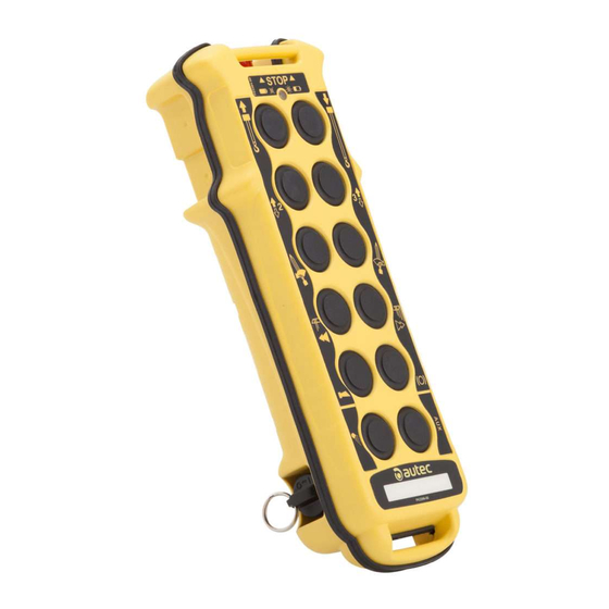
- allegato “Limitazioni & Autorizzazioni”. Verificare che siano presenti questi documenti allegati: in caso contrario farne richiesta ad Autec specificando il numero di matricola del radiocomando. CERTIFICATO DI GARANZIA Le condizioni che regolano la garanzia del radiocomando sono riportate sul “Certificato di Garanzia”... - Page 9 LIMKNPU2 UNITÀ TRASMITTENTE MK10, MK12 Queste unità trasmittenti possono essere utilizzate con una delle seguenti unità riceventi: - Type R102 - Type R202 MK10 chiave d’accensione pulsante di STOP led di segnalazione attuatori a pulsante targhetta dati tecnici, targhetta di C1 pulsante attuatore identificazione (nel vano batteria)
- Page 10 LIMKNPU2 MK12 chiave d’accensione pulsante di STOP led di segnalazione attuatori a pulsante targhetta dati tecnici, targhetta di C1 pulsante attuatore identificazione (sul fondo) (se pre- C2 selettore a levetta pulsante di START sente) C3 selettore a chiave batteria Pagina 6 Pagina 5...
- Page 11 LIMKNPU2 Le unità trasmittenti della serie Modular sono dotate di un doppio controllo che protegge il sistema “radiocomando+macchina”, in posizione neutra (di riposo), dai movimenti involontari dovuti ad eventuali guasti del radiocomando. DATI TECNICI UNITÀ TRASMITTENTE MK10, MK12 Alimentazione (pacco batteria MBM06MH) * NiMH 7,2Vdc Antenna interna...
-
Page 12: Avvertenze Per L'uso
LIMKNPU2 AVVERTENZE PER L’USO L’OPERATORE DOVRÀ SEMPRE SEGUIRE A VISTA tutti i movimenti della macchina e del carico rimanendo all’interno del raggio d’azione tipico. POSIZIONARSI nelle condizioni migliori di visibilità diretta del sistema “macchina+radiocomando” e del carico. Prima di iniziare lavorare, VERIFICARE sempre il corretto funzionamento meccanico del pulsante di STOP: se non funziona, non utilizzare il radiocomando. -
Page 13: Avvertenze Per La Manutenzione
TRASMITTENTE. Eventuali guasti possono essere riparati esclusivamente da personale autorizzato, utilizzando soltanto pezzi di ricambio originali Autec. L’unità trasmittente non necessita di particolari manutenzioni, tuttavia per lavorare con un’unità sempre efficace e sicura è necessario: PRIMA DELL’USO: - verificare che l’unità sia integra, - controllare che le guarnizioni, i soffietti ed i cappucci degli attuatori (selettori e pulsanti) siano integri, morbidi ed elastici e che i simboli del pannello siano ben visibili. - Page 14 LIMKNPU2 FUNZIONAMENTO UNITÀ TRASMITTENTE MK10, MK12 ACCENSIONE ED AVVIAMENTO Per accendere l’unità trasmittente, inserire la chiave d’accensione e ruotarla nella posizione “I”. Per avviare le funzioni del radiocomando, premere il pulsante di START per 1÷2 ATTIVAZIONE secondi. COMANDI Dopo l’avviamento si accende sempre il Azionare gli attuatori a led di segnalazione verde.
- Page 15 LIMKNPU2 SPEGNIMENTO L’unità trasmittente deve essere spenta ogni volta che si sospende il lavoro girando la chiave d’accensione in posizione “O” ed estraendola (riporla sempre in un luogo sicuro). Lo spegnimento dell’unità trasmittente può anche avvenire quando la batteria non è sufficientemente carica e/o quando il radiocomando non viene utilizzato per circa 3,5 minuti (impostazioni DIP n°1: vedere paragrafo 8...
- Page 16 434.050 - 434.790 MHz. Nei radiocomandi AUTEC la frequenza radio di lavoro appartiene all’insieme delle frequenze ammesse dalle normative europee in vigore al momento dell’immissione nel mercato.
- Page 17 LIMKNPU2 PROGRAMMAZIONI La programmazione dei dip switches deve essere eseguita con unità trasmittente senza batteria e può essere effettuata soltanto da personale autorizzato. DIP SWITCHES NEL MODULO RADIO TRASMITTENTE E16STXEU_ Il gruppo di otto dip switches presente Gruppo di 4 nel modulo serve a programmare dip switches alcune funzionalità...
- Page 18 LIMKNPU2 DIAGNOSTICA UNITÀ TRASMITTENTE MK10, MK12 Nel caso in cui il sistema “macchina + radiocomando” non si avvii, è opportuno controllare se il problema interessa il radiocomando o la macchina. Perciò, prima di qualunque verifica, controllare con il posto comando a cavo il funzionamento della macchina: - se non si avvia, il problema interessa la macchina stessa - se si avvia, il problema riguarda il radiocomando.
-
Page 19: Table Des Matières
LIMKNPU2 INDEX AND CONVENTIONS INDEX Page Index and Conventions Introduction to Modular series MK10, MK12 transmitting unit Warnings for use Warnings for maintenance MK10, MK12 operation transmitting unit Frequencies Programming MK10, MK12 transmitting unit diagnostic CONVENTIONS In this manual, all important information is indicated using the following symbols and conventions: abcd. -
Page 20: Introduction To Modular Series
Each radio remote control is also in conformity with the norms given in the EC conformity declaration supplied with this manual. Autec cannot be held responsible if the radio remote control is installed on applications that are different from those permitted... - Page 21 The machine producer and/or the person who decides upon radio remote control use and installation is responsible for this analysis. Autec cannot be held responsible if the risk analysis is not carried out correctly. To guarantee correct radio remote control operation, all current regulations regarding safety at work and accident prevention should be respected.
- Page 22 - the enclosed “Limitations & Authorisations”. Make sure that the following documents have been supplied: if they are not, request them from Autec. Please specify the radio remote control serial number. CERTIFICATE OF GUARANTEE The conditions of the radio remote control guarantee are given in the “Certificate of Guarantee”...
-
Page 23: Mk10, Mk12 Transmitting Unit
LIMKNPU2 MK10, MK12 TRANSMITTING UNIT These transmitting units can be used with one of the following receiving units: - Type R102 - Type R202 MK10 starting keyswitch STOP pushbutton signalling LED actuators pushbutton technical data plate, identification C1 pushbutton actuator plate (in the battery housing) C2 toggle switch START pushbutton... - Page 24 LIMKNPU2 MK12 starting keyswitch STOP pushbutton signalling LED actuators pushbutton technical data plate, identification C1 pushbutton actuator plate (in the battery housing) C2 toggle switch START pushbutton present) C3 keyswitch selector battery Page 6...
- Page 25 LIMKNPU2 The transmitting units of Modular series are equipped with a redundant control that protects the “radio remote control + machine” system, when it is in neutral (rest position), from involuntary movements caused by possible radio remote control faults. MK10, MK12 TRANSMITTING UNIT TECHNICAL DATA Power supply (battery pack MBM06MH) * NiMH 7,2Vdc Antenna...
-
Page 26: Warnings For Use
LIMKNPU2 WARNINGS FOR USE THE OPERATOR MUST ALWA YS VISUALLY FOLLOW all movements of the machine and its load remaining inside radio remote control typical working range. BE POSITIONED in a way that permits him to see the “machine + radio remote control” system, and above all the load, in the best possible way. -
Page 27: Before Using
FROM THE TRANSMITTING UNIT BEFORE CARRYING OUT ANY MAINTENANCE WORK. Any faults should be repaired by authorised Autec personnel using original Autec spare parts only . No particular maintenance needs to be carried out on the transmitting unit, but the... -
Page 28: Mk10, Mk12 Operation Transmitting Unit
LIMKNPU2 MK10, MK12 OPERATION TRANSMITTING UNIT POWER AND STARTING To switch on the transmitting unit, insert the starting key and turn it to "I". To start the radio remote control functions, press the “START” button for 1÷2 seconds. COMMAND ACTIVATION After starting, the green signalling LED always lights up. - Page 29 LIMKNPU2 SWITCHING OFF The transmitting unit should be switched off each time work is stopped by turning the ignition key to "O" and extracting it (always put the key in a safe place). The unit may also switch off if the battery is not sufficiently charged and/or when the radio remote control is not used for more than 3,5 minutes (set DIP nr.
-
Page 30: Frequencies
European countries permit the use of industrial remote controls only in the 434.040 - 434.790 MHz band. The radio frequency of AUTEC radio remote controls is included in the group of frequencies permitted by those European regulations that are current at the moment of radio remote control entry onto the market. -
Page 31: Programming
LIMKNPU2 PROGRAMMING The dip switches must be programmed with the battery removed from the transmitting unit and can be done only by authorised personnel. DIP SWITCHES ON E16STXEU_ RADIO TRANSMITTING MODULE Group of 4 The group of eight dip switches found dip switches in the module is necessary for programming some operations and... -
Page 32: Mk10, Mk12 Transmitting Unit Diagnostic
LIMKNPU2 MK10, MK12 TRANSMITTING UNIT DIAGNOSTICS If the “machine+radio remote control” system does not start, check if the problem is caused by the radio remote control or the machine. Before carrying out any verifications, check the functioning of the machine with the cable control panel: - if it does not switch on, the problem lies with the machine itself - if it does switch on, the problem lies with the radio remote control. -
Page 33: Abcd
LIMKNPU2 INDEX UND KONVENTIONEN INDEX Seite Index und Konventionen Einleitung Serie Modular Sendereinheit MK10, MK12 Gebrauchsanweisungen Wartungsanweisungen Arbeitsweise Sendereinheit MK10, MK12 Frequenzen Programmierung endereinheit -Fehlersuche KONVENTIONEN In diesem Handbuch werden alle wichtigen Informationen mit den folgenden Symbolen und Konventionen hervorgehoben: abcd. -
Page 34: Einleitung Serie Modular
99/05/CE und ihren wesentlichen Erfordernissen überein. Außerdem stimmt jede Funkfernsteuerung mit allen Vorschriften überein, die in der beiliegenden Konformitätserklärung "CE" aufgeführt sind. Autec kann keine Verantwortung übernehmen, wenn die Funkfernsteuerung für Anwendungszwecke benutzt wird, die von den vorgesehenen abweichen GESTATTETE ANWENDUNGEN Maschinen für die Hebung von Materialien (Baukrane, industrielle... - Page 35 Die Verantwortung dieser Analyse liegt beim Hersteller der Maschine und/oder bei demjenigen, der die Installation und die Verwendung einer Funkfernsteuerung bestimmt. Autec kann keine Verantwortung übernehmen, falls die Risikoanalyse nicht korrekt ausgeführt wurde. Um einen einwandfreien Betrieb der Funkfernsteuerung zu garantieren, müssen stets alle Vorschriften zur Arbeitssicherheit und Unfallverhütung am Arbeitsplatz beachtet...
- Page 36 - dem Schaltplan - der Beilage “Beschränkungen & Genehmigungen”. Bitte überprüfen Sie, ob Sie über diese beiliegenden Dokumente verfügen: anderenfalls sollte man Autec um die entsprechende Zulieferung bitten, indem man die Seriennummer der Funkfernsteuerung angibt. GARANTIESCHEIN Die Bedingungen, die die Garantie der Funkfernsteuerung regeln, sind auf dem “Garantieschein”...
-
Page 37: Sendereinheit Mk10, Mk12
LIMKNPU2 SENDEEINHEIT MK10, MK12 Diese Sendeeinheiten können mit einer der folgenden Empfangseinheiten verwendet werden: - Type R102 - Type R202 MK10 Schlüssel STOP-Drucktaste Kontroll-LED Bewegungsbedienung Technische Angeben Schild C1 Drucktaste Identifikationsschild (im Bedienung Batteriegehäuse) (falls C2 Kippschalter START-Drucktaste vorhanden) Schlüsselwähl- Akku Schalter Seite 5... - Page 38 LIMKNPU2 MK12 Schlüssel STOP-Drucktaste Kontroll-LED Bewegungsbedienung Technische Angeben Schild C1 Drucktaste Identifikationsschild (im Bedienung Batteriegehäuse) (falls C2 Kippschalter START-Drucktaste vorhanden) Schlüsselwähl- Akku Schalter Seite 6...
- Page 39 LIMKNPU2 Die Sendeeinheiten der Serie Modular sind mit einer doppelten Kontrolle versehen, die das System “Funkfernsteuerung + Maschine” in Leerstellung (Ruhestellung) vor ungewollten Bewegungen schützt, die durch eventuelle Schäden an der Funkfernsteuerung verursacht werden könnten. TECHNISCHE DATEN MK10, MK12 SENDEREINHEIT Versorgungsspannung (Batteriepaket) * NiMH 7,2V Antenne...
-
Page 40: Gebrauchsanweisungen
LIMKNPU2 GEBRAUCHSANWEISUNGEN DER ARBEITER MUß Alle Bewegungen der Maschine und der Ladung MIT DEN AUGEN VERFOLGEN, indem man jedoch im Aktionsradius bleibt. ich so POSITIONIEREN, daß er die beste Sicht über das System “Maschine + Funkfernsteuerung ” und vor allem über die Last hat. Bevor man beginnt, die Funkfernsteuerung zu benutzen, sollte man stets den einwandfreien mechanischen Betrieb der STOP-Drucktaste ÜBERPRÜFEN. -
Page 41: Wartungsanweisungen
SENDEEINHEIT ENTFERNT WURDE. Eventuelle Schäden können ausschließlich von autorisiertem Autec-Personal repariert werden, indem sie nur Originalersatzteile von Autec benutzen. Die Sendeeinheit benötigt keine besonderen Wartungen, trotzdem sind folgende Schritte notwendig, um mit einer stets wirksamen und sicheren Einheit arbeiten zu können:... -
Page 42: Arbeitsweise Sendereinheit Mk10, Mk12
LIMKNPU2 ARBEITSWEISE SENDEEINHEIT MK10, MK12 E I N S C H A L T U N G U N D S TA R T Um die Sendeeinheit anzustellen, den Zündschlüssel einführen und ihn auf Position "I" drehen. Um die Funktionen der Funkfernsteuerung in AKTIVIERUNG Betrieb zu setzen, die Drucktaste “START”... - Page 43 LIMKNPU2 AUSSCHALTEN Die Sendeeinheit muß jedes Mal, wenn man die Arbeit unterbricht, ausgestellt werden, indem man den Zündschlüssel auf Position "O" dreht und ihn dann herauszieht (den Schlüssel stets an einen sicheren Ort bringen). Die Sendeeinheit kann sich auch ausschalten, wenn die Batterie nicht ausreichend geladen ist und/oder wenn die Funkfernsteuerung für Dreieinhalb Minuten nicht benutzt wurde...
-
Page 44: Frequenzen
Inbetriebnahme Überprüfen. Z.B.: Einige europäische Staaten genehmigen den Gebrauch dieser Funkgeräte nur im Bereich 434.040 - 434.790 MHz. Die Arbeitsfrequenz der Funkfernsteuerungen von AUTEC liegt innerhalb der Frequenzen, die zur Zeit der Markteinführung gemäß den europäischen Vorschriften zulässig waren. Der Konstrukteur hat die Funkfernsteuerung mit die Modalitäten einer AUTOMATISCHEN ABTASTUNG (Standardprogrammierung des Erbauers) erbaut oder einer MANUELLEN WAHL. -
Page 45: Programmierung
LIMKNPU2 PROGRAMMIERUNG Die Programmierung der dip switch muß mit der Sendeeinheit ohne Batterie durchgeführt werden und nur von autorisiertem Personal sein werden. DIP SWITCHES IM SENDEMODUL E16STXEU_ Die Gruppe der acht dip switches, die Gruppe von 4 sich im Modul befinden, dient dazu, dip switches e i n i g e F u n k t i o n a l i t ä... -
Page 46: Endereinheit -Fehlersuche
LIMKNPU2 ENDEREINHEIT -FEHLERSUCHE Im Falle, dass das System “Maschine + Funkfernsteuerung” nicht angeht, ist es vorteilhaft, zu kontrollieren, ob das Problem die Funkfernsteuerung oder die Maschine betrifft. Somit sollte man vor jeglicher Kontrolle zuerst die Arbeitsweise der Maschine mit der verkabelten Befehlsstelle kontrollieren: - falls sie sich nicht einschaltet, betrifft das Problem die Maschine - falls sie sich einschaltet, betrifft das Problem die Funkfernsteuerung. -
Page 47: Index Et Conventions
LIMKNPU2 INDEX ET CONVENTIONS INDEX Page Index et Conventions Introduction série Modular Unité de Transmission MK10, MK12 Conseils pour l’emploi Conseils pour l’entretien Fonctionnement de unité de transmission MK10, MK12 Fréquences Reglages Diagnostic de l’unité de transmission MK10, MK12 CONVENTIONS Dans ce manuel toutes les informations importantes sont mises en évidence à... - Page 48 Chaque radiocommande est en outre conforme aux normes reportées dans la déclaration de conformité CE jointe à ce manuel. La maison Autec ne pourra en aucun cas être tenue responsable si la radiocommande est installée sur des applications différentes de celles...
- Page 49 Le constructeur de la machine et/ou la personne qui décide l'installation et l'utilisation de la radiocommande est responsable de cette analyse. Autec ne pourra assumer aucune responsabilité si cette analyse des risques n'a pas étée effectuée de façon correcte. Pour garantir le fonctionnement correct de la radiocommande, toutes les prescriptions en vigueur sur la sécurité...
-
Page 50: Instructions Pour La Gestion Des Documents
- annexe “Limitations & Autorisations”. Vérifier que ces documents soient bien joints: en cas contraire, en faire la demande à Autec en spécifiant le numéro de série de la radiocommande. CERTIFICAT DE GARANTIE es conditions concernant la garantie de la radiocommande sont indiquées sur le “Certificat de Garantie”... -
Page 51: Unite De Transmission Mk10, Mk12
LIMKNPU2 UNITE DE TRANSMISSION MK10, MK12 Ces unités de transmission peuvent être utilisées avec une des unités de réception suivantes: - Type R102 - Type R202 MK10 clé d’allumage bouton de STOP voyant de signalisation actionneur à bouton-poussoir données technique plaque, plaque C1 bouton d’identification (dans le compartiment actionneur... - Page 52 LIMKNPU2 MK12 clé d’allumage bouton de STOP voyant de signalisation actionneur à bouton-poussoir données technique plaque, plaque C1 bouton d’identification (dans le compartiment actionneur batterie) C2 sélecteur à levier bouton-poussoir de START présente) sélecteur à clé batterie d’allumage Page 6...
-
Page 53: Donnees Techniques Unite De Transmission
LIMKNPU2 Les unités de transmission de la série Modular sont équipées d'un double contrôle qui protège le système “radiocommande+machine”, en position neutre (de repos), contre les mouvements involontaires dus à d'éventuelles pannes de la radiocommande. MK10, MK12 DONNEES TECHNIQUES UNITE DE TRANSMISSION Alimentation (piles MBM06MH) * NiMH 7,2Vdc Antenne... -
Page 54: Conseils Pour L'emploi
LIMKNPU2 CONSEILS POUR L’EMPLOI L’OPERATEUR DEVRA: SUIVRE DE VUE tous les mouvements de la machine et du chargement restant à l'intérieur du rayon d'action typique. Se PLACER dans les meilleures conditions de visibilité directe du système “machine + radiocommande” et surtout du chargement. Avant de commencer à... -
Page 55: Conseils Pour L'entretien
D'ENTRETIEN, S'ASSURER QUE LA BATTERIE SOIT ENLEVEE DE L'UNITE DE TRANSMISSION. Les éventuelles pannes peuvent être réparées exclusivement par du personnel autorisé Autec, en utilisant seulement des pièces de rechange originales Autec. L'unité de transmission n'a besoin d'aucun entretien particulier, toutefois pour travailler avec une unité... -
Page 56: Fonctionnement De L'unité De Transmission Mk10, Mk12
LIMKNPU2 FONCTIONNEMENT DE L'UNITÉ DE TRANSMISSION MK10, MK12 ALLUMAGE ET MISE EN MARCHE Pour allumer l'unité de transmission, insérer la clé d'allumage et la tourner dans la position "I". P o u r m e t t r e l e s f o n c t i o n s d e l a ACTIVATION radiocommande en marche, actionner le DES COMMANDES... - Page 57 LIMKNPU2 EXTINCTION L'unité de transmission doit être éteinte chaque fois qu'on suspend le travail en tournant la clé d'allumage en position "O" et en l'extrayant (toujours la déposer en lieu sûr). L'extinction de l'unité de transmission peut aussi advenir quand la batterie n'est pas suffisamment chargée et/ou quand la radiocommande n'est pas utilisée pendant 3,5 minutes (programmations DIP n°1: voir...
-
Page 58: Modalite De Selection Manuelle
434.040 - 434.790 MHz. Dans les radiocommandes AUTEC la fréquence radio de travail appartient à l'ensemble des fréquences admises par les normatives européennes en vigueur au moment de l'introduction sur le marché. -
Page 59: Dip Switch Dans Le Module Radio Émetteur E16Stxeu
LIMKNPU2 REGLAGES La programmation des dip switch doit être effectuée avec l'unité de transmission sans batterie et peut être effectué exclusivement par du personnel autorisé. DIP SWITCH DANS LE MODULE RADIO ÉMETTEUR E16STXEU_ Le groupe de huit dip switches présent Groupe de 4 dans le module sert à... -
Page 60: Diagnostic De L'unite De Transmission Mk10, Mk12
LIMKNPU2 DIAGNOSTIC DE L’UNITE DE TRANSMISSION MK10, MK12 Au cas où le système “machine + radiocommande” ne se mettrait pas en marche il faudrait contrôler si le problème concerne la radiocommande ou la machine. Avant toute vérification et à l'aide du poste de commande câblé, contrôler aussi le fonctionnement de la machine: - si elle ne démarre pas, le problème intéresse la machine elle-même - si elle démarre, le problème concerne la radiocommande. - Page 61 LIMKNPU2 ÍNDICE Y CONVENCIONES ÍNDICE Pag. Índice y Conveciónes Introducción serie Modular Unidad transmisora MK10, MK12 Advertencias de empleo Advertencias para el mantenimiento Funcionamiento unidad transmisora MK10, MK12 Frecuencias Regulaciones Diagnóstica de la unidad transmisora MK10, MK12 CONVENCIONES En este manual, todas las informaciones importantes se indican con las siguientes simbologías: abcd.
- Page 62 Cada telemando es además conforme a las normas que se indican en la declaración de conformidad CE anexa a este manual. Autec no se asume ninguna responsabilidad si el telemando ha sido instalado en aplicaciones diferentes de aquellas consentidas APLICACIONES PERMITIDAS Máquinas para la elevación de materiales (grúas, puentes grúa...
- Page 63 Este análisis es responsabilidad del fabricante de la máquina misma o de quién decide instalar y utilizar el telemando. Autec no se asume ninguna responsabilidad si este análisis de riesgos no se ha efectuado de modo correcto. Para poder garantizar el funcionamiento correcto del telemando, se tienen que respetar siempre todas las instrucciones sobre la seguridad en el trabajo y sobre la prevención de...
-
Page 64: Certificado De Garantía
- anexo “Limitaciones & Autorizaciones”. Comprobar que se hallen estos documentos anexos: si no fuera así, solicitarlos a Autec especificando el número de matrícula del telemando. CERTIFICADO DE GARANTÍA as condiciones que regulan la garantía del telemando se indican el “Certificado de Garantía”... - Page 65 LIMKNPU2 UNIDAD TRANSMISORA MK10, MK12 Estas unidades transmisoras se pueden emplear con una de las siguientes unidades receptoras: - Type R102 - Type R202 MK10 llave de encendido pulsador de STOP led de señalización actuadores a pulsador placa de datos técnicos, placa de C1 pulsador identificación (en el alojamiento de la actuador...
- Page 66 LIMKNPU2 MK12 llave de encendido pulsador de STOP led de señalización actuadores a pulsador placa de datos técnicos, placa de C1 pulsador identificación (en el alojamiento de la actuador batería) (si está) C2 selector de palanca pulsador de START C3 selector con llave batería Pagina 6 Página 5...
- Page 67 LIMKNPU2 Las unidades transmisoras de la serie Modular están equipadas de un doble control que protege el sistema "telemando+máquina", en posición neutra (de descanso), de los movimientos involuntarios debidos a posibles averías del telemando. DATOS TÉCNICOS UNIDAD TRANSMISORA MK10, MK12 Alimentación (batería MBM06MH) * NiMH 7,2Vdc interna...
- Page 68 LIMKNPU2 ADVERTENCIAS DE EMPLEO EL OPERARIO DEBERÁ S E G U I R E N M O D O V I S I B L E t o d o s l o s m o v i m i e n t o s de la máquina y de la carga permaneciendo al interior del radio de acción COLOCARSE...
-
Page 69: Advertencias Para El Mantenimiento
TRANSMISORA. Las averías que pudieran surgir tendrán que ser reparadas exclusivamente por personal autorizado Autec, utilizando únicamente piezas de repuesto originales Autec. La unidad transmisora no necesita particulares manutenciones, pero para poder trabajar con una unidad eficaz y segura hay que:... - Page 70 LIMKNPU2 FUNCIONAMIENTO UNIDAD TRANSMISORA MK10, MK12 ENCENDIDO Y ACTIVACIÓN Para poder acceder a la unidad transmisora, hay que introducir la llave de encendido y girarla en la posición "I". Para activar las funciones del telemando, accionar el pulsador de “START” por 1 ÷...
- Page 71 LIMKNPU2 DESCONEXIÓN La unidad transmisora se debe apagar cada vez que se suspenda el trabajo girando la llave de encendido en la posición "O" y extrayéndola (hay que colocarla siempre en un lugar seguro). La desconexión de la unidad transmisora se puede producir también cuando la batería no está...
- Page 72 Por ejemplo, algunos estados europeos permiten l'empleo de estos aparatos radio sólo en la banda de frecuencia 433.050 - 434.790 MHz. En los telemandos AUTEC la frecuencia radio de funcionamiento pertenece al conjunto de frecuencias admitidas por las normativas europeas en vigor al momento de su introducción en el mercado.
- Page 73 LIMKNPU2 REGULACIONES La programación de los dip switch se debe efectuar con la unidad transmisora sin batería y debe ser efectuada par personal especializado. DIP SWITCHES EN EL MÓDULO RADIO TRANSMISOR E16STXEU_ El grupo de ocho dip switches que hay Grupo de 4 en el módulo sirve para programar dip switches...
- Page 74 LIMKNPU2 DIAGNÓSTICA UNIDAD TRANSMISORA MK10, MK12 En el caso en que el sistema “máquina + telemando” no se ponga en funcionamiento, es oportuno controlar si el problema proviene del telemando o de la máquina. Por lo tanto, antes de llamar al servicio técnico comprovar que la máquina funcione correctamente con la botonera de cable.
- Page 75 Appendix: FREQUENCY TABLE 433.050 - 434.790 MHz DIP SWITCH DIP SWITCH 433.125 434.100 OFF OFF OFF OFF OFF OFF OFF OFF 433.200 434.125 OFF OFF OFF OFF 433.250 434.150 OFF OFF 433.325 434.225 433.400 OFF OFF 434.300 434.325 433.425 OFF OFF 433.475 434.350 433.500...
- Page 76 Tel : ++39 - 0444/901000 r.a. Tel : ++39 - 0444/901000 r.a. Via Pomaroli, 65 Via Pomaroli, 65 email: info@autec.it email: info@autec.it 36030 Caldogno (VI) ITALY 36030 Caldogno (VI) ITALY Fax: ++39 - 0444/901011 Fax: ++39 - 0444/901011 http://www.autec.it http://www.autec.it...