Se connecter
Télécharger
Manuels
Marques
Agilent Technologies Manuels
Contrôleurs
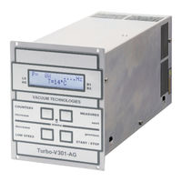
Turbo-V 301-AG
Agilent Technologies Turbo-V 301-AG Manuels
Manuels et Guides d'utilisation pour Agilent Technologies Turbo-V 301-AG. Nous avons
1
Agilent Technologies Turbo-V 301-AG manuel disponible en téléchargement PDF gratuit: Notice De Mode D'emploi
Agilent Technologies Turbo-V 301-AG Notice De Mode D'emploi (294 pages)
Marque:
Agilent Technologies
| Catégorie:
Contrôleurs
| Taille: 7.79 MB
Table des Matières
Table des Matières
5
Istruzioni Per L'uso
15
Informazioni Generali
16
Immagazzinamento
17
Preparazione Per L'installazione
18
Installazione
19
Uso
20
Comandi, Indicatori E Connettori
21
Descrizione Pannello Frontale
21
Procedure DI Uso
23
Manutenzione
23
Accensione del Controller
23
Avvio Della Pompa
23
Arresto Della Pompa
23
Smaltimento
24
Messaggi DI Errore
25
Deutsch
27
Gebrauchsanleitung
27
Allgemeines
28
Lagerung
29
Vor der Installation
30
Installation
31
Gebrauch
32
Steuerungen, Anzeigen und Verbinder des Controllers
32
Fronttafel der Controller
33
Bedienung
35
Einschalten des Controllers
35
Pumpenstart
35
Pumpenstopp
35
Wartung
35
Entsorgung
36
Fehlermeldungen
37
Français
39
Mode D'emploi
39
Indications Generales
40
Emmagasinage
41
Preparation pour L'installation
42
Installation
43
Utilisation
44
Commandes, Indicateurs et Connecteurs
45
Description du Tableau Avant
45
Allumage du Contrôleur
47
Arrêt de la Pompe
47
Entretien
47
Mise en Marche de la Pompe
47
Procedures D'utilisation
47
Mise au Rebut
48
Messages D'erreur
49
Español
51
Manual de Istrucciones
51
Información General
52
Almacenamiento
53
Preparación para la Instalación
54
Instalación
55
Uso
56
Descripción del Panel Frontal
57
Mandos, Indicadores y Conectores
57
Encendido del Controler59
59
Mantenimiento
59
Parada de la Bomba
59
Procedimientos de Uso
59
Puesta en Marcha de la Bomba
59
Eliminación
60
Mensajes de Error
61
Português
63
Manual de Istruções
63
Informações Gerais
64
Armazenagem
65
Preparação para a Instalação
66
Instalação
67
Utilização
68
Comandos, Indicadores E Conectores
69
Descrição Painel Frontal
69
Acendimento Do Controller
71
Activação da Bomba
71
Manutenção
71
Paragem da Bomba
71
Procedimentos de Uso
71
Eliminação
72
Mensagens de Erro
73
Dutch
75
Bedrijfshandleiding
75
Algemene Informatie
76
Opslag
77
Voorbereiding Voor Installatie
78
Installatie
79
Gebruik
80
Bedieningsorganen, Controlelampjes en Connectoren Van
81
Beschrijving Frontpaneel
81
Gebruiksprocedures
83
Inschakelen Van de Controller
83
Onderhoud
83
Starten Van de Pomp
83
Stoppen Van de Pomp
83
Afvalverwerking
84
Foutmeldingen
85
Dansk
87
Istruktionsbog
87
Generel Information
88
Opbevaring
89
Forberedelser Før Installation
90
Installation
91
Anvendelse
92
Beskrivelse Af Frontpanel
93
Indikatorer Og Kontakter På Styreenheden
93
Instruktion
95
Start Af Pumpen
95
Start Af Styreenheden
95
Stop Af Pumpen
95
Vedligeholdelse
95
Bortskaffelse
96
Fejlmeddelelser
97
Svenska
99
Bruksanvisning
99
Allmän Information
100
Förvaring
101
Förberedelser För Installation
102
Installation
103
Användning
104
Beskrivning Av Frontpanel
105
Indikatorer Och Kontakterpå Styrenheten
105
Instruktioner För Bruk
107
Start Av Pumpen
107
Start Av Styrenheten
107
Stopp Av Pumpen
107
Underhåll
107
Bortskaffning
108
Felmeddelanden
109
Norsk
111
Instruksjon Manual
111
Generell Informasjon
112
Lagring
113
Forberede Installasjonen
114
Installasjon
115
Bruk
116
Beskrivelse Av Frontpanelet
117
Indikatorer Og Kontakter På Styreenheten
117
Instruksjoner for Bruk
119
Starte Pumpen
119
Starte Styreenheten
119
Stoppe Pumpen
119
Vedlikehold
119
Eliminering
120
Feilmeldinger
121
Suomi
123
Ohjekäsikirja
123
Yleisiä Tietoja
124
Varastointi
125
Valmistelut Asennusta Varten
126
Asennus
127
Käyttö
128
Etupaneelin Kuvaus
129
Valvojan Säätimet, Osoittimet Ja Liittimet
129
Huolto
131
Käyttötoimenpiteet
131
Pumpun Käynnistys
131
Pumpun Pysäyttäminen
131
Valvojan Käynnistys
131
Hävittäminen
132
Vianetsintä
133
Magyar
135
FelhasználóI Kézikönyv
135
Általános InformáCIók
136
Tárolás
137
A Telepítésre Való Előkészítés
138
Telepítés
139
Használat
140
A Vezérlő Parancsai, KijelzőI És CsatlakozóI
141
Az Előlap Leírása
141
A Szivattyú Beindítása
143
A Szivattyú Leállítása
143
A Vezérlő Bekapcsolása
143
Használati Eljárások
143
Karbantartás
143
Megsemmisítés
144
Hibaüzenetek
145
Polski
147
Podrecznik Instrukcji
147
Informacje Ogolne
148
Magazynowanie
149
Przygotowanie Do Instalacji
150
Instalacja
151
Uzytkowanie
152
Opis Pulpitu Frontalnego
153
Sterowniki, Wskazniki I Laczniki
153
Konserwacja
155
Procedure Uzytkowania
155
Uruchomienie Pompy
155
Zaswiecenie Kontrolera
155
Zatrzymanie Pompy
155
Przetworstwo Odpadow
156
Bledne Informacje
157
Čeština
159
Návod K Použití
159
Všeobecné Informace
160
Uskladnění
161
Příprava K Instalaci
162
Instalace
163
Použití
164
OvláDání, Indikátory a Konektory
165
Popis Čelního Panelu
165
Používané Procedury
167
Spouštění Čerpadla
167
Zapalování Kontroléru
167
Zastavení Čerpadla
167
Údržba
167
Likvidace
168
Chybné Zprávy
169
Slovenčina
171
Návod Na Obsluhu
171
Všeobecné Informácie
172
Uskladňovanie
173
Príprava Pre Inštaláciu
174
Inštalácia
175
Použitie
176
Popis Čelného Panelu
177
Povely, Ukazovatele a Prípojky "Controller
177
Naštartovanie Čerpadla
179
Postup Pri Použití
179
Zapnutie "Controller
179
Zastavenie Čerpadla
179
Údržba
179
Likvidácia
180
Oznamy VáD
181
Slovenščina
183
Priročnik Za Navodila
183
Splošne Informacije
184
Skladiščenje
185
Priprava Za Montažo
186
Montaža
187
Uporaba
188
Komande, Indikatorji in Konektorji
189
Opis Prednje Plošče
189
Postopki Uporabe
191
Vklopitev Controllera
191
Vzdrževanje
191
Zagon Črpalke
191
Zaustavitev Črpalke
191
Odlaganje Opadkov
192
Obvestilo O Napaki
193
English
195
Instructions for Use
195
General Information
196
Storage
197
Preparation for Installation
198
Installation
199
Use
200
Controls, Indicators and Connectors
201
Front Panel Description
201
Controller Startup
203
Maintenance
203
Pump Shutdown
203
Starting the Pump
203
Use Procedure
203
Disposal
204
Error Messages
205
Technical Information
207
Turbo-V 301 Rack Controller Description
209
Controller Specifications
211
Controller Outline
212
Controller Connection
213
J6 - Fan
213
J7 - Vent
214
P1 - Input
215
J1 - Output
216
R1 - R2 Output Diagrams
220
Programmable Analog Output Diagrams
222
J5 - Gauge Connector
223
Pump Connector
223
Pump Driving
224
Stop Speed Reading and Active Stop
225
J2 - Serial Connector
226
Connector Examples
227
Serial Communication Descriptions
228
Letter Protocol Description
229
Communication Protocol
235
Description
235
Examples
238
Window Meanings
241
How to Use by Front Panel
245
General
250
Use
250
Startup
251
Configuration Menu
256
Programming
256
Mode Menu
258
Pump Setting Menu
259
Input/Output Menu
261
Setpoint R1 and Setpoint R2 Submenus
264
Gauge Menu
266
Serial Menu
267
How to Use by Remote I/0
268
How to Use in Serial Mode
268
General
270
Installation
270
Profibus Option
270
Configuration
271
Software Operation and State Machine
271
Message Mapping
273
Parameter Buffer
274
Output Buffer
277
Input Buffer
278
Diagnostic Management
280
Diagnostic Buffer
282
Error Messages
284
Orderable Parts
287
Publicité
Publicité
Produits Connexes
Agilent Technologies TwisTorr 304 FS AG
Agilent Technologies Turbo-V 3K-T
Agilent Technologies Turbo-V 300 ICE
Agilent Technologies Turbo-V 70 PCB 24 Vdc
Agilent Technologies Turbo-V 81 PCB 24 Vdc
Agilent Technologies Turbo-V 550
Agilent Technologies Turbo-V 81-AG
Agilent Technologies Turbo-V 2300 Rack Controller
Agilent Technologies Turbo-V 1001 Rack
Agilent Technologies Turbo-V 2300 TwisTorr
Agilent Technologies Catégories
Équipement de laboratoire
Pompes
Contrôleurs
Appareils de mesure
Multimètres
Plus Manuels Agilent Technologies
Connexion
Se connecter
OU
Se connecter avec Facebook
Se connecter avec Google
Télécharger le manuel
Télécharger depuis le disque dur
Télécharger depuis l'URL