
Manuels Connexes pour Horizon Hobby E-Flite PA-20 Pacer 10e


Sommaire des Matières pour Horizon Hobby E-Flite PA-20 Pacer 10e
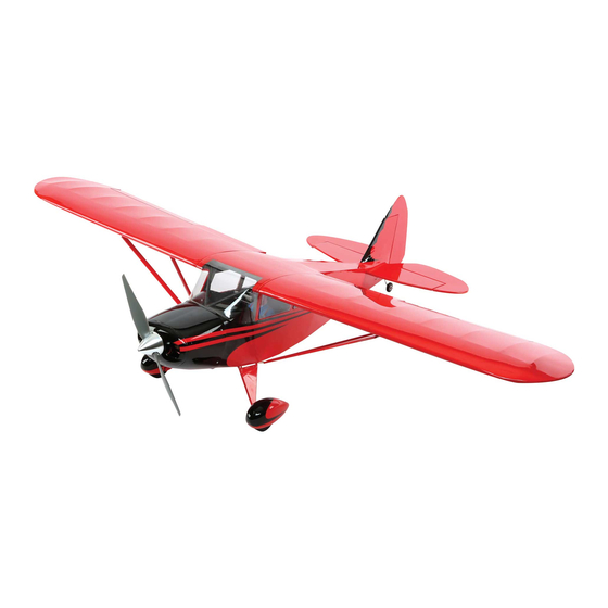
- Page 1 PA-20 Pacer 10e ALMOST-READY-TO-FLY Instruction Manual Bedienungsanleitung Manuel d’utilisation Manuale di Istruzioni...
-
Page 2: Safety Warnings And Precautions
Do not use with incompatible components or alter this product in any way outside of the instructions This kit includes small parts and should not be left provided by Horizon Hobby, Inc. This manual contains instructions for safety, operation and maintenance. It is unattended near children as choking and serious injury essential to read and follow all the instructions and warnings in the manual, prior to assembly, setup or use, in could result. -
Page 3: Warnungen Und Sicherheit- Svorkehrungen
Folgen Sie immer den Herstelleranweisungen bei dem Gebrauch oder Entsorgung von Akkus. Falsche jedweder Art ausserhalb der von Horizon Hobby, Inc. vorgegebenen Anweisungen. Diese Bedienungsanleitung Behandlung von Li-Po Akkus kann zu Feuer mit enthält Anweisungen für Sicherheit, Betrieb und Wartung. Es ist unbedingt notwendig, vor Zusammenbau, Körperverletzungen und Sachbeschädigung führen. -
Page 4: Avertissements Relatifs À La Sécurité
La totalité des instructions, garanties et autres documents est sujette à modifi cation à la seule discrétion d’Horizon Hobby, Inc. Pour obtenir la documentation à jour, rendez-vous sur le site horizonhobby.com et cliquez sur Lisez et suivez toutes les instructions relatives à la •... -
Page 5: Avvertimenti E Precauzioni Per La Sicurezza
Non usare componenti non Piccole parti compatibili o alterare il prodotto in nessuna maniera al di fuori delle istruzioni fornite da Horizon Hobby, Inc. Questo manuale contiene le istruzioni per un funzionamento e una manutenzione sicuri. È fondamentale leggere e seguire Questo kit comprende delle parti di piccole dimensioni e non lo si può... -
Page 6: Large Parts Layout
SPECIFICATIONS•SPEZIFIKATIONEN• •LARGE PARTS LAYOUT SPÉCIFICATIONS•SPECIFICHE •BAUTEILE (OHNE KLEINTEILE) •GRANDES PIÈCES •SCHEMA DEI COMPONENTI GRANDI 51.0 in (1300mm) 451 sq in (29.1 dm2) 36.3 in (920mm) 46.4–48.0 oz (1300–1360 g) Electric Power Power: Power 10 Brushless Elektro Antrieb Power: Power 10 Brushless Moteur électrique (EP): Power 10 Brushless Motore elettrico: Power 10 Brushless 4-channel (or greater) with 4–6 servos... - Page 7 REQUIRED RADIO EQUIPMENT•ERFORDERLICHE RC AUSRÜSTUNG•EQUIPEMENT RADIO REQUIS•APPARECCHIATURE RADIO Part English Deutsch Français Italiano SPMAR600 AR600 Full-Range Sport Receiver AR 600 Sport Empfänger mit voller Reichweite Récepteur longue portée AR600 Sport Ricevitore sport AR600 a piena portata EFLRDS76 (4)* 7.6-Gram DS76 Digital Sub-Micro Servo 7.6-Gram DS76 Digital Sub-Micro Servo Sub micro servo digital 7.6g DS76 7.6-Gram DS76 Digital Sub-Micro Servo...
- Page 8 REQUIRED TOOLS•BENÖTIGTES WERKZEUG•OUTILS REQUIS•ATTREZZI NECESSARI English Deutsch Français Italiano Box wrench: 10mm Ringschlüssel: 10mm Clé plate fermée 10mm Chiave a tubo: 10mm Drill bit: 1/16-inch, 5/64-inch, 1/8-inch Bohrer: 1,5 mm, 2mm, 3mm Foret : 1,5 mm, 2mm, 3mm Punte per trapano: 1,5 mm, 2mm, 3mm Felt-tipped pen Faserstift Feutre fi...
-
Page 9: Before Starting Assembly
BEFORE STARTING ASSEMBLY VOR DEM ZUSAMMENBAU AVANT DE COMMENCER PRIMA DI INIZIARE IL MONTAGGIO L’ASSEMBLAGE • Remove parts from bag. • Entnehmen Sie zur Überprüfung jedes Teil der • Togliere tutti i pezzi dalla scatola. Verpackung. • Retirez toutes les pièces des sachets pour les •... - Page 10 ASSEMBLY SYMBOL GUIDE•MONTAGE SYMBOLE•GUIDE DES SYMBOLES POUR ASSEMBLAGE•GUIDA AI SIMBOLI DI ASSEMBLAGGIO Use medium CA Repeat multiple times (as indicated) Use hobby knife with #11 blade Mittelfl üssigen Sekundenkleber verwenden Vorgang wiederholen (wie angezeigt) Verwenden Sie ein Hobbymesser mit # 11 Klinge Utilisez de la colle cyanoacrylate moyenne Répétez comme indiqué...
- Page 11 HINGING THE AILERONS AND FLAPS•MONTAGE DER QUERRUDER UND KLAPPEN• INSTALLATION DES CHARNIÈRES D’AILERONS ET DE VOLETS•METTERE LE CERNIERE AD ALETTONI E FLAP Remove the aileron and fl ap from the wing. Use a pin vise and 1/16-inch (1.5mm) drill bit to drill a hole in the center of each hinge slot.
- Page 12 AILERON SERVO INSTALLATION• EINBAU DES QUERRUDERSERVO• INSTALLATION DES SERVOS D’AILERONS• INSTALLAZIONE SERVO ALETTONE Apply thin CA to the top and bottom of each hinge. Once Trim the portion of the control horn that fi ts into the Check the fi...
- Page 13 Thread a servo mounting screw into each of the holes in Apply a small amount of thin CA to harden the threads Secure the servo to the cover using the screws provided Center the aileron servo using the radio system. With the aileron servo mounting holes.
- Page 14 M2 x 10 Secure a 3-inch (76mm) extension to the servo lead Thread a screw into each of the holes in the aileron Apply a small amount of thin CA to harden the threads using string or dental fl oss. servo cover mounting holes.
- Page 15 M2 x 10 Secure the servo cover to the wing using four M2 x 10 Thread the clevis on a pre-bent M2 x 75 aileron rod. This self-tapping screws. pushrod has a Z-bend in the end as shown. Schrauben Sie die Servoklappe an die Tragfl...
- Page 16 FLAP SERVO INSTALLATION•EINBAU DER KLAPPENSERVOS•INSTALLATION DES SERVOS DE VOLETS•INSTALLAZIONE SERVO FLAP The following section covers the installation of the flap servo for those modelers wanting to utilize operational flaps. For those that will build the model with fixed flaps, skip to the next section of the manual, Fixed Flap Installation section, located on Page 17.
- Page 17 FIXED FLAP INSTALLATION•EINBAU FESTE KLAPPEN•INSTALLATION DES VOLETS FIXES•INSTALLAZIONE PER I FLAP FISSI The following section covers the installation of the fixed flap mount for those modelers wanting to utilize fixed flaps. For those that have built their model with operational flaps, skip to the next section of the manual, Landing Gear Installation section, located on page 18.
- Page 18 LANDING GEAR INSTALLATION•EINBAU DES FAHRWERK•INSTALLATION DU TRAIN D’ATTERRISSAGE•INSTALLAZIONE DEL CARRELLO 2 3 4 M2 x 10 Thread a mounting screw into each of the holes to cut Place the wheel in the wheel pant, centering it in the Place the wheel pant on a fl...
- Page 19 5 6 7 M3 x 3 M3 x 6 1/8 inch Secure the mounting bracket inside the wheel pant using Fit the wheel pant on the axle. Slide the wheel collar on With the fuselage inverted on the work surface, hold the (3mm) 1/2 inch 11/32 inch...
- Page 20 Make sure the wheel pants are close to the alignment as shown in Step 10 before marking the location for the wheel pant supports. Bitte stellen Sie sicher, dass die Radschuhe wie im Schritt 10 beschrieben ausgerichtet sind bevor Sie markieren.
- Page 21 RADIO INSTALLATION•RC EINBAU•INSTALLATION DE LA RADIO•INSTALLAZIONE DEL RADIOCOMANDO WING INSTALLATION• MONTAGE DER TRAGFLÄCHE• INSTALLATION DE L’AILE• INSTALLAZIONE DELL’ALA Remove the bottom hatch from the fuselage. Set the Use hook and loop tape to attach the receiver to the hatch aside in a safe location.
- Page 22 M3 x 10 Wrap a piece of tape around a 5/64-inch (2mm) drill bit 3/8 inch (10mm) from the end of the drill bit to act as a depth gauge when drilling the holes for the wing tube Use the drill bit prepared in the previous step to drill Thread a screw into the wing rod.
- Page 23 STABILIZER INSTALLATION•MONTAGE DES HÖHENRUDERS• INSTALLATION DU STABILISATEUR•INSTALLAZIONE DELLO STABILIZZATORE Remove ONE wing panel and use thin CA to harden the threads cut into the wing tube. Allow the CA to FULLY CURE, Check that the stabilizer and wing are parallel to each Slide the stabilizer into position in the fuselage.
- Page 24 NOTICE: Do not cut into the underlying wood. This will weaken the structure and could cause failure in flight. As an option, use a soldering iron or hot knife with light pressure to carefully melt the covering and avoid the potential of cutting into the wood.
- Page 25 Use sandpaper to lightly sand the elevator joiner wire where it will fi t into the elevators. Slide the stabilizer back into the fuselage. After checking Use a pin vise and 1/16-inch (1.5mm) drill bit to drill Schleifen Sie mit Schleifpapier den Leitwerksverbinder an the alignment, wick thin CA along the joint between the a hole in the center of each hinge slot to allow the CA...
- Page 26 RUDDER INSTALLATION•EINBAU DES SEITENLEITWERKS•INSTALLATION DE LA DÉRIVE•INSTALLAZIONE DEL TIMONE Apply a small amount of petroleum jelly to the tail gear Use sandpaper to lightly sand the tail wheel wire where Fit the tail gear wire into the rudder. It must rest so the Once the epoxy has fully cured, check that the wire near the bushing.
- Page 27 Use a pin vise and 1/16-inch (1.5mm) drill bit to drill a hole in the center of each hinge slot to allow the CA to wick into the hinge. Drill holes in the rudder and fi n at this time. Place a T-pin in the center of the two hinges. Slide the hinges into position with the T-pin resting against the edge of the control surface.
- Page 28 RUDDER AND ELEVATOR LINKAGE INSTALLATION•EINBAU SEITEN- UND HÖHENRUDERANLENKUNG• INSTALLATION DES TRINGLERIES DE PROFONDEUR ET DE DÉRIVE• INSTALLAZIONE COLLEGAMENTI PER TIMONE ED ELEVATORE 1 2 Once the epoxy fully cures, apply thin CA to both sides of each hinge. Once the CA cures, gently pull on the fi xed Insert the Z-bend of the 17 -inch (440mm) pushrod surface and control surface to make sure the hinges are...
- Page 29 3 4 M3 x 3 Slide the pushrod into the elevator pushrod tube inside the fuselage. With the radio system on, center the elevator stick and trim. Secure the servo arm so it is Prepare a clevis by placing a piece of silicone tubing Repeat Steps 1 through 4 to install the rudder control Slide the wheel on the tail gear wire.
- Page 30 MOTOR INSTALLATION•MOTOREINBAU•INSTALLATION DU MOTEUR•INSTALLAZIONE DEL MOTORE M3 x 12 Attach the X-mount to the motor using the hardware Secure the motor to the motor box using the hardware provided with the motor. listed. Schrauben Sie den X-Halter an den Motor mit den Schrauben Sie den Motor mit den aufgeführten Schrauben aus dem Lieferumfang des Motors an.
- Page 31 COWLING INSTALLATION•MONTAGE DER MOTORHAUBE•INSTALLATION DU CAPOT•INSTALLAZIONE DELLA CAPOTTINA MOTORE CAUTION: Never check the motor rotation on the bench with the propeller installed. The plane could move and cause serious injury. To avoid injury, always check the motor without the propeller. ACHTUNG: Überprüfen Sie niemals die Drehrichtung des Motors mit montierten Propeller.
- Page 32 Important Information About Your Propeller Always ensure the propeller is balanced before installing it onto the shaft. An unbalanced propeller may cause poor flight characteristics. Wichtige Information über ihren Propeller Stellen Sie immer sicher das der Propeller gewuchtet ist bevor Sie ihn montieren.
- Page 33 WING STRUT INSTALLATION•MONTAGE DER TRAGFLÄCHENSTREBEN•INSTALLATION DES HAUBANS•INSTALLAZIONE DEI MONTANTI DELL’ALA M2 x 10 Thread a mounting screw into the pre-drilled holes in the Make sure the strut has been installed so the wider Check that the holes on the strut ends align with the pre- fuselage.
- Page 34 WINDOW AND INTERIOR INSTALLATION•EINBAU DER FENSTER UND INTERIEUR• INSTALLATION DES VITRAGES ET DE L’INTÉRIEUR•INSTALLAZIONE FINESTRATURE E INTERNI Use black electrical tape to attach the fi rst 4 inches (102mm) of the 9-inch (228mm) fl ap and aileron servo leads. Insert the leads into the slot in the cockpit fl...
- Page 35 Use hobby scissors to trim the excess material from the Use silicone adhesive to glue the seatback to the cockpit Repeat steps 4 and 5 for the front seatbacks. The front rear seatback. Leave a lip of 1/16–1/8 inch (1.5–3mm) fl...
- Page 36 Use silicone adhesive to glue the pilot in the cockpit. Fit the windows into the fuselage from the inside. Use Use canopy glue to secure the windshield to the hobby scissors to trim the windows as necessary. fuselage.
-
Page 37: Der Schwerpunkt
CENTER OF GRAVITY DER SCHWERPUNKT CENTRE DE GRAVITÉ CENTRO DI GRAVITA’ (BARICENTRO) An important part of preparing the aircraft for fl ight is Ein sehr wichtiger Teil in der Flugvorbereitung ist es das Une des étapes importantes de la préparation d’un Un punto importante per preparare l’aereo al volo è... -
Page 38: Control Throws
CONTROL THROWS RUDERAUSSCHLÄGE 1. Turn on the transmitter and receiver of your model. Check the movement of the rudder using the transmitter. 1. Schalten Sie den Sender und Empfänger ihres Modells ein. Prüfen Sie die Seitenruderaussschläge mit dem Sender. When the stick is moved to the right, the rudder should also move right. Reverse the direction of the servo at the Bewegen Sie den Seitenruderstick nach rechts, sollte sich das Ruder auch nach rechts bewegen. -
Page 39: Débattements
DÉBATTEMENTS CORSE DEI COMANDI 1. Mettez l’émetteur et le récepteur sous tension. Contrôlez les mouvements de la dérive en utilisant votre émetteur. 1. Accendere trasmettitore e ricevitore del modello. Controllare i movimenti del timone agendo sul trasmettitore. Quand le manche est vers la droite, la dérive doit s’orienter vers la droite. Inversez la direction du servo à l’émetteur Quando lo stick va a destra, anche il timone deve andare a destra. -
Page 40: Preflight Checklist
PREFLIGHT CHECKLIST VORFLUGKONTROLLE CHECKLIST D’AVANT VOL LISTA DEI CONTROLLI PRIMA DEL VOLO • Charge the transmitter, receiver and motor • Laden Sie den Sender- ,Empfänger- und Zündakku • Chargez la batterie de votre émetteur, de réception • Caricare le batterie di trasmettitore, ricevitore battery for your airplane. -
Page 41: Daily Flight Checks
DAILY FLIGHT CHECKS TÄGLICHER FLUG CHECK CONTRÔLES SYSTÉMATIQUES CONTROLLI DI VOLO GIORNALIERI • Check the battery voltage of the transmitter battery. • Überprüfen Sie die Spannung des Senderakkus. • Contrôlez la tension de la batterie de l’émetteur. • Controllare la tensione della batteria del Do not fl... - Page 42 Limitation of Liability Inspection or Services Non-Warranty Service Horizon Hobby, Inc. (“Horizon”) warrants to the original HORIZON SHALL NOT BE LIABLE FOR SPECIAL, If this Product needs to be inspected or serviced and Should your service not be covered by purchaser that the product purchased (the “Product”)
-
Page 43: Garantie Und Service Informationen
Liegt eine kostenpfl ichtige Reparatur vor, erstellen enthält Sicherheitshinweise und Vorschriften sowie wurden aus. Rücksendungen durch den Käufer direkt an Exklusive Garantie ¬ Horizon Hobby Inc (Horizon) wir einen Kostenvoranschlag, den wir Ihrem Händler Hinweise für die Wartung und den Betrieb des Horizon oder eine seiner Landesvertretung bedürfen der... -
Page 44: Garantie Et Réparations
La garantie ne couvre pas les dégâts résultant d’un montage ou d’une manipulation erronés, d’accidents Garantie exclusive - Horizon Hobby, Inc. (Horizon) Votre revendeur spécialisé local et le point de vente En cas de réparation payante, nous établissons un devis ou encore du fonctionnement ainsi que des tentatives garantit que le Produit acheté... - Page 45 Periodo di garanzia Limiti di danno Manutenzione e riparazione La garanzia esclusiva - Horizon Hobby, Inc., (Horizon) Horizon non si riterrà responsabile per danni speciali, Se il prodotto deve essere ispezionato o riparato, garantisce che i prodotti acquistati (il “Prodotto”) sono diretti, indiretti o consequenziali;...
-
Page 46: Instructions For Disposal Of Weee By Users In The European Union
Harlow, Essex, CM18 7NS, United Kingdom +44 (0) 1279 641 097 Horizon Technischer Service service@horizonhobby.de Christian-Junge-Straße 1 Germany 25337 Elmshorn, Germany Sales: Horizon Hobby GmbH +49 (0) 4121 2655 100 infofrance@horizonhobby.com Service/Parts/Sales: 11 Rue Georges Charpak France Horizon Hobby SAS... -
Page 47: Ama National Model Aircraft Safety Code
AMA NATIONAL MODEL AIRCRAFT SAFETY CODE Effective January 1, 2013 (h) Not operate model aircraft while under the infl uence B. RADIO CONTROL (RC) 7. Under no circumstances may a pilot or other person of alcohol or while using any drug which could adversely touch a model aircraft in fl... - Page 48 © 2013 Horizon Hobby, Inc. E-fl ite and Celectra are trademarks or registered trademarks of Horizon Hobby, Inc. The Spektrum trademark is used with permission of Bachmann Industries, Inc. All other trademarks, service marks and logos are the property of their respective owners.