Publicité
Liens rapides
22180-3FR-01
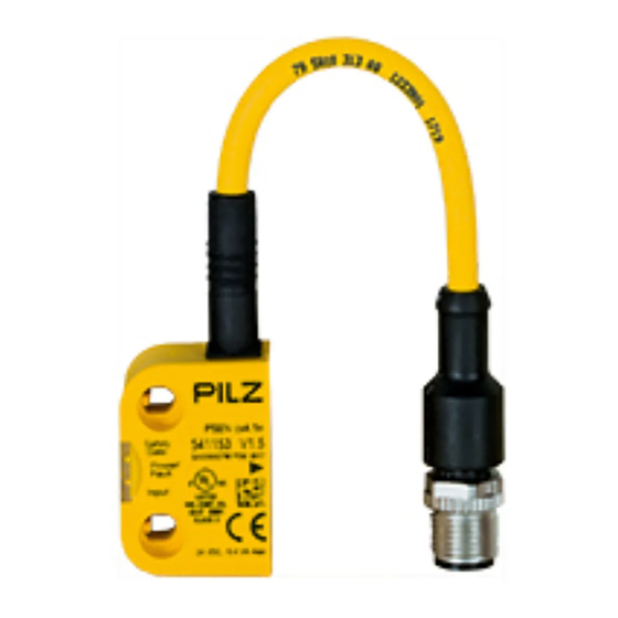
PSEN cs4.1n
PSEN cs4.1n
22180-3FR-01
Sicherheitsschalter PSEN cs4.1n
Der Sicherheitsschalter erfüllt die Anforderun-
1185799819
gen nach:
EN 60204-1
EN 60947-5-3: PDF-M zusammen mit dem
Betätiger (siehe Technische Daten).
EN 62061: SIL CL 3
EN ISO 13849-1. PL e und Kat. 4
Der Sicherheitsschalter darf nur mit dem zu-
gehörigen Betätiger verwendet werden (sie-
he Technische Daten).
Die Sicherheitsausgänge müssen 2-kanalig
weiterverarbeitet werden.
Zu Ihrer Sicherheit
Installieren und nehmen Sie das Gerät nur
547263243
dann in Betrieb, wenn Sie diese Betriebsan-
leitung gelesen und verstanden haben und
Sie mit den geltenden Vorschriften über Ar-
beitssicherheit und Unfallverhütung vertraut
sind.
Beachten Sie die VDE- sowie die örtlichen
Vorschriften, insbesondere hinsichtlich
Schutzmaßnahmen
Durch Öffnen des Gehäuses oder eigen-
mächtige Umbauten erlischt jegliche Ge-
währleistung.
777809547
Entfernen Sie die Schutzkappe erst unmittel-
bar vor Anschluss des Geräts.
Gerätemerkmale
Transpondertechnik
1245094667
Zweikanaliger Betrieb
2 Sicherheitsausgänge
LED-Anzeige für:
– Zustand Betätiger
– Versorgungsspannung/Fehler
1 Betätigungsrichtung
5-poliger M12 Stiftstecker
Codierung: vollcodiert
Blockschaltbild
Safety switch PSEN cs4.1n
The safety switch meets the requirements in
accordance with:
EN 60204-1
EN 60947-5-3: PDF-M in conjunction with
the actuator (see Technical Details).
EN 62061: SIL CL 3
EN ISO 13849-1. PL e and Cat. 4
The safety switch may only be used with the
corresponding actuator (see Technical De-
tails).
The safety outputs must use 2-channel
processing.
For your safety
Only install and commission the unit if you
have read and understood these operating
instructions and are familiar with the applica-
ble regulations for health and safety at work
and accident prevention.
Ensure VDE and local regulations are met,
especially those relating to safety.
Any guarantee is rendered invalid if the hous-
ing is opened or unauthorised modifications
are carried out.
Do not remove the protective cap until you
are just about to connect the unit.
Unit features
Transponder technology
Dual-channel operation
2 safety outputs
LED for:
– Status of the actuator
– Supply voltage/fault
1 direction of actuation
5 pin M12 male connector
Coding: fully coded
Block diagram
- 1 -
Capteur de sécurité PSEN cs4.1n
Le capteur de sécurité satisfait aux exigences
des normes :
EN 60204-1
EN 60947-5-3 : PDF-M avec l'actionneur
(voir les caractéristiques techniques).
EN 62061 : SIL CL 3
EN ISO 13849-1. PL e et cat. 4
Le capteur de sécurité doit être utilisé uni-
quement avec l'actionneur correspondant
(voir les caractéristiques techniques).
Les sorties de sécurité doivent être traitées
par 2 canaux.
Pour votre sécurité
Vous n'installerez l'appareil et ne le mettrez
en service qu'après avoir lu et compris le
présent manuel d'utilisation et vous être fa-
miliarisé avec les prescriptions en vigueur
sur la sécurité du travail et la prévention des
accidents.
Respectez les normes locales ou VDE, parti-
culièrement en ce qui concerne la sécurité.
L'ouverture de l'appareil ou sa modification
annule automatiquement la garantie.
Veuillez retirer le cache de protection avant
de raccorder l'appareil.
Caractéristiques de l'appareil
Technique à transpondeur
Commande par 2 canaux
2 sorties de sécurité
LEDs de visualisation :
– état de l'actionneur
– tension d'alimentation / défauts
1 sens de manœuvre
Connecteur mâle à 5 broches M12
Code : codé multiple
Schéma de principe
Publicité

Manuels Connexes pour Pilz PSEN cs4.1n


Sommaire des Matières pour Pilz PSEN cs4.1n
- Page 1 22180-3FR-01 PSEN cs4.1n 22180-3FR-01 PSEN cs4.1n Sicherheitsschalter PSEN cs4.1n Safety switch PSEN cs4.1n Capteur de sécurité PSEN cs4.1n 1185799819 Der Sicherheitsschalter erfüllt die Anforderun- The safety switch meets the requirements in Le capteur de sécurité satisfait aux exigences gen nach:...
- Page 2 Funktionsbeschreibung Function description Description du fonctionnement Die Sicherheitsausgänge 12 und 22 leiten, Safety outputs 12 and 22 conduct when Les sorties de sécurité 12 et 22 sont sous ten- 1176789259 wenn the actuator is in the response range sion si der Betätiger sich im Ansprechbereich befin- Safety outputs 12 and 22 are disabled when l'actionneur se trouve dans la zone de détec-...
- Page 3 PIN/ Adernfarbe (Pilz Kabel)/ Blockschaltbild/ Function/ Broche Cable colour (Cable Pilz)/ Terminal designation/ Foncion Couleur du fil (fil de Pilz) Désignation des bornes +24 UB braun/brown/marron Ausgang Kanal 1/ weiß/white/blanc Output, channel 1/ Canal de sortie 1 Ausgang Kanal 2/...
- Page 4 Anschaltung Interface Raccordement Anschluss an PDP67 Connection to PDP67 Raccordement à PDP67 PSENcode PDP67 Test Pulse X / 24 V DC Input X Input X + 1 Test Pulse X + 1 / 24 V DC n.c. - 4 -...
- Page 5 Anschluss an PNOZ X, PNOZpower, PNOZ- Connection to PNOZ X, PNOZpower, Raccordement aux PNOZ X, PNOZpower, sigma, PNOZelog PNOZsigma, PNOZelog PNOZsigma, PNOZelog - 5 -...
- Page 6 PSENcode PNOZ n.c. Anschluss an PNOZmulti Connection to PNOZmulti Raccordement au PNOZmulti Schutztür/safety gate/protecteur mobile Schaltertyp 3/switchtype 3/type du capteure 3 I0, I1: Eingänge OSSD/inputs OSSD/entrées OSSD Anschluss an PSS Connection to PSS Raccordement au PSS Schutztür/safety gate/protecteur mobile Standardbaustein SB64/standard block SB64/bloc standard SB64 I0, I1: Eingänge/inputs/entrées - 6 -...
- Page 7 Einlernen des Betätigers Teaching in the actuator Programmation de l'organe de com- 1175997707 Erstmaliges Einlernen des Betätigers: Teaching in the actuator for the first time: mande par apprentissage Der erste vom Sicherheitsschalter erkannte zu- The first corresponding actuator to be detected Première programmation de l'actionneur : gehörige Betätiger (siehe Technische Daten) by the safety switch (see Technical Details) is...
- Page 8 Montage Variante 1 Installation type 1 Montage du modèle 1 1086268427 1. Gewinde (M4) in gewünschter Position 1. Cut the thread (M4) in the required posi- 1. Couper le filetage (M4) dans la position schneiden. tion. souhaitée. 2. Sensor mit einer Schraube fixieren. 2.
- Page 9 Montage Variante 2 Installation type 2 Montage du modèle 2 Montieren Sie den Sensor wie bei Montage Va- Install the sensor as shown for installation type Montez le capteur de la même manière que 1086273035 riante 1 pour le modèle 1 1.
- Page 10 Betrieb Operation Utilisation 1176970891 Prüfen Sie vor der Inbetriebnahme die Funktion Check the function of the safety switch before Vérifiez le fonctionnement du capteur de sécu- des Sicherheitsschalters. commissioning. rité avant sa mise en service. Statusanzeigen: Status indicators: Affichages des états : LED "POWER/Fault"...
- Page 11 Elektrische Daten Electrical data Données électriques Max. Gesamtleitungswiderstand R Max. overall cable resistance R Résistance max. de l'ensemble du 1000 Ohm lmax im Eingangskreis in the input circuit câblage R dans le circuit d'en- lmax trée Max. Leitungskapazität an den Si- Max.
- Page 12 Bevollmächtigter: Norbert Fröhlich, Pilz GmbH Authorised representative: Norbert Fröhlich, Représentant : Norbert Fröhlich, Pilz GmbH & & Co. KG, Felix-Wankel-Str. 2, 73760 Ostfil- Pilz GmbH & Co. KG, Felix-Wankel-Str. 2, Co. KG, Felix-Wankel-Str. 2, 73760 Ostfildern,...