Publicité
Liens rapides
22111-01
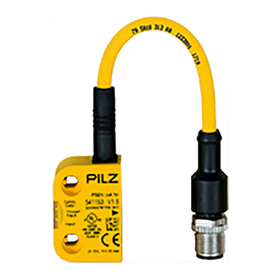
PSEN cs3.1
4
D
Betriebsanleitung
4
GB Operating instructions
4
F
Manuel d'utilisation
PSEN cs3.1
22111-01
Sicherheitsschalter PSEN cs3.1
1086077195
Der Sicherheitsschalter erfüllt die Anforderun-
gen nach:
EN 60204-1 und IEC 60204-1
EN 60947-5-3 mit Betätiger PSEN cs3.1
EN 62061: SIL CL 3
EN ISO 13849-1: PL e und Kat. 4
Der Sicherheitsschalter darf nur mit dem zuge-
hörigen Betätiger PSEN cs3.1 verwendet wer-
den.
Die Sicherheitsausgänge müssen 2-kanalig
weiterverarbeitet werden.
Zu Ihrer Sicherheit
547263243
Installieren und nehmen Sie das Gerät nur
dann in Betrieb, wenn Sie diese Betriebsan-
leitung gelesen und verstanden haben und
Sie mit den geltenden Vorschriften über Ar-
beitssicherheit und Unfallverhütung vertraut
sind.
Beachten Sie die VDE- sowie die örtlichen
Vorschriften, insbesondere hinsichtlich
Schutzmaßnahmen
Durch Öffnen des Gehäuses oder eigen-
mächtige Umbauten erlischt jegliche Ge-
währleistung.
777809547
Entfernen Sie die Schutzkappe erst unmittel-
bar vor Anschluss des Geräts.
Gerätemerkmale
1067977483
Transpondertechnik
Gerätevarianten:
– PSEN cs3.1a: mit Kabel (5 m)
– PSEN cs3.1b: mit Kabel (10 m)
– PSEN cs3.1p: 8-pol. M8
– PSEN cs3.1 M12/8-1.5m: 8-pol. M12
Codierung: codiert
Zweikanaliger Betrieb
2 Sicherheitseingänge für Reihenschaltung
mehrerer Sicherheitsschalter
2 Sicherheitsausgänge
1 Meldeausgang
LED-Anzeige für:
– Zustand Betätiger
– Zustand Eingänge
– Versorgungsspannung/Fehler
1 Betätigungsrichtung
Blockschaltbild
Safety switch PSEN cs3.1
The safety switch meets the requirements in
accordance with:
EN 60204-1 and IEC 60204-1
EN 60947-5-3 with the actuator PSEN cs3.1
EN 62061: SIL CL 3
EN ISO 13849-1: PL e and Cat. 4
The safety switch may only be used with the
corresponding actuator PSEN cs3.1
The safety outputs must use 2-channel
processing.
For your safety
Only install and commission the unit if you
have read and understood these operating
instructions and are familiar with the applica-
ble regulations for health and safety at work
and accident prevention.
Ensure VDE and local regulations are met,
especially those relating to safety.
Any guarantee is rendered invalid if the hous-
ing is opened or unauthorised modifications
are carried out.
Do not remove the protective cap until you
are just about to connect the unit.
Unit features
Transponder technology
Unit types:
– PSEN cs3.1a: with cable (5 m)
– PSEN cs3.1b: with cable (10 m)
– PSEN cs3.1p: 8 pin M8
– PSEN cs3.1 M12/8-1.5m: 8 pin M12
Coding: coded
Dual-channel operation
2 safety inputs for series connection of sev-
eral safety switches
2 safety outputs
1 signal output
LED for:
– Status of the actuator
– Status of the inputs
– Supply voltage/fault
1 direction of actuation
Block diagram
A1 A2
S11 S21
Input
&
Power
12 22
Capteur de sécurité PSEN cs3.1
Le capteur de sécurité satisfait aux exigences
des normes suivantes :
EN 60204-1 et CEI 60204-1
EN 60947-5-3 avec l'actionneur PSEN cs3.1
EN 62061 : SIL CL 3
EN ISO 13849-1 : PL e et cat. 4
Le capteur de sécurité doit être utilisé unique-
ment avec l'actionneur PSEN cs3.1 correspon-
dant.
Les sorties de sécurité doivent être traitées par
2 canaux.
Pour votre sécurité
Vous n'installerez l'appareil et ne le mettrez
en service qu'après avoir lu et compris le
présent manuel d'utilisation et vous être fa-
miliarisé avec les prescriptions en vigueur
sur la sécurité du travail et la prévention des
accidents.
Respectez les normes locales ou VDE, parti-
culièrement en ce qui concerne la sécurité.
L'ouverture de l'appareil ou sa modification
annule automatiquement la garantie.
Veuillez retirer le cache de protection avant
de raccorder l'appareil.
Caractéristiques de l'appareil
Technique à transpondeur
Modèles d'appareils :
– PSEN cs3.1a : avec câble (5 m)
– PSEN cs3.1b : avec câble (10 m)
– PSEN cs3.1p : M8 à 8 broches
– PSEN cs3.1 M12/8-1.5 : M12 à 8 broches
Codage : codé
Commande par 2 canaux
2 entrées de sécurité pour le montage en sé-
rie de plusieurs capteurs de sécurité
2 sorties de sécurité
1 sortie de signalisation
LED de visualisation pour les états suivants :
– état de l'actionneur
– état des entrées
– tension d'alimentation / défauts
1 sens de manœuvre
Schéma de principe
Receiver
Y32
- 1 -
Actuator
Publicité

Manuels Connexes pour Pilz PSEN cs3.1


Sommaire des Matières pour Pilz PSEN cs3.1
- Page 1 – PSEN cs3.1p: 8 pin M8 – PSEN cs3.1p : M8 à 8 broches – PSEN cs3.1 M12/8-1.5m: 8-pol. M12 – PSEN cs3.1 M12/8-1.5m: 8 pin M12 – PSEN cs3.1 M12/8-1.5 : M12 à 8 broches Codierung: codiert Coding: coded Codage : codé...
- Page 2 Funktionsbeschreibung Function description Description du fonctionnement Die Sicherheitsausgänge 12 und 22 leiten, Safety outputs 12 and 22 conduct when Les sorties de sécurité 12 et 22 sont conductri- 1080085643 wenn The actuator is within the response range ces si Der Betätiger im Ansprechbereich ist und die and inputs S11 and S21 are high l'actionneur est dans la zone de déclenche- Eingänge S11 und S21 high sind...
- Page 3 Seiten- und Höhenversatz Lateral and vertical offset Décalage latéral et en hauteur 8 10 10 mm Legende Légende 1075264139 : Hysterese : Hysteresis : Hystérésis : Typischer Schaltabstand S : Typical operating distance S : Distance approximative de commutation : Typischer Ausschaltabstand S : Typical release distance S : Versatz in mm : Offset in mm...
- Page 4 Funktion/ PIN/ Adernfarbe (Pilz Kabel)/ Blockschaltbild/ Function/ Broche Cable colour (Cable Pilz)/ Terminal designation/ Foncion Couleur du fil (fil de Pilz) Désignation des bornes Eingang Kanal 2/ weiß/white/blanc Input, channel 2/ Canal d'entrée 2 +24 UB braun/brown/marron Ausgang Kanal 1/ grün/green/vert...
- Page 5 Anschluss an Auswertegeräte Connection to evaluation devices Raccordement aux appareils de contrôle 1090417163 ACHTUNG! CAUTION! ATTENTION ! Die Sicherheitsausgänge müssen 2-ka- The safety outputs must use 2-channel Les sorties de sécurité doivent être trai- nalig weiterverarbeitet werden. processing. tées par 2 canaux. 1067372427 INFO INFORMATION...
- Page 6 Reihenschaltung Series connection Montage en série 1022409355 ACHTUNG! CAUTION! ATTENTION ! Bei Reihenschaltung mehrerer Geräte ad- When several units are connected in series, Si plusieurs appareils sont montés en série, diert sich die Rückfallverzögerung mit der the delay-on de-energisation time increas- la temporisation à...
- Page 7 Anschluss an PNOZ X, PNOZpower, PNOZ- Connection to PNOZ X, PNOZpower, Raccordement aux PNOZ X, PNOZpower, sigma, PNOZelog PNOZsigma, PNOZelog PNOZsigma, PNOZelog PSENcode PNOZ PNOZ X2.7P PNOZ X2.8P PNOZ X4 PNOZ X8P n.c. PNOZ X9P PSENcode PNOZ n.c. PNOZ X3P PNOZ X3.10P PNOZ XV3P PNOZ XV3.1P...
- Page 8 1095050635 erkannt, sobald er in den Ansprechbereich ge- soon as it is brought into the response range. Chaque actionneur (PSEN cs3.1) est reconnu bracht wird. par Pilz dès qu'il entre dans la zone de déclen- chement. - 8 -...
- Page 9 Montage Installation Montage 1086339595 Montieren Sie Sicherheitsschalter und Betä- The safety switch and actuator should be in- Montez le capteur de sécurité et l'actionneur tiger parallel gegenüberliegend. stalled opposite each other in parallel. l'un en face de l'autre de manière parallèle. ACHTUNG! CAUTION! ATTENTION !
- Page 10 Montage Variante 1 Installation type 1 Montage du modèle 1 1086268427 1. Gewinde (M4) in gewünschter Position 1. Cut the thread (M4) in the required posi- 1. Couper le filetage (M4) dans la position schneiden. tion. souhaitée. 2. Sensor mit einer Schraube fixieren. 2.
- Page 11 Montage Variante 2 Installation type 2 Montage du modèle 2 1086273035 Montieren Sie den Sensor wie bei Montage Va- Install the sensor as shown for installation type Montez le capteur de la même manière que riante 1 pour le modèle 1 1.
- Page 12 Betrieb Operation Utilisation 1086405899 Prüfen Sie vor der Inbetriebnahme die Funktion Check the function of the safety switch before Avant la mise en service, veuillez vérifer la fonc- des Sicherheitsschalters. commissioning. tion du capteur de sécurité. Statusanzeigen: Status indicators: Affichages d'état : LED "POWER/Fault"...
- Page 13 Anschlussart Connection type Type de connection 5 m cable (PSEN cs3.1a) 10 m cable (PSEN cs3.1b) M8 (PSEN cs3.1p) M12 (PSEN cs3.1 M12/8-1.5m) Leitung Cable Câble LiYY 8 x 0,14 mm² Schutzart Protection type Indice de protection IP67 (PSEN cs3.1p/...
- Page 14 Données mécaniques Gewicht Weight Poids Sensor Sensor Capteur 35 g (PSEN cs3.1p) 230 g (PSEN cs3.1a) 435 g (PSEN cs3.1b) 95 g (PSEN cs3.1 M12/8-1.5m) Betätiger Actuator Actionneur 15 g Sicherheitstechnische Kennda- Safety-related characteristic Caractéristiques techniques de data sécurité PL nach EN ISO 13849-1...