Publicité
Les langues disponibles
Les langues disponibles
Liens rapides
GB
PARTS
IDENTIFICATION
Remove cover by loosening the bottom fixing screw revealing the inside of the Door Contact.
LED indicator
Tamper Switch
Jumper On
The jumper link is inserted.
JP1 = Test / Normal Mode Jumper
Jumper (ON): Door Contact is in Test mode.
Jumper (OFF): Door Contact is in Normal mode (Factory default).
JP2 = Supervision Enable / Disable Jumper Switch
Jumper (ON): Supervision disabled (Factory default).
Jumper (OFF): Supervision enabled
JP3 = Internal Magnet Switch Bypass Jumper Switch
Jumper (ON): the internal magnet switch is bypassed. Only the device connected to the Extension
Terminal will activate the Door Contact.
Jumper (OFF): the internal magnet switch is in use (Factory default).
JP4 = Door Close Confirmation Enable / Disable Jumper Switch
Jumper (ON): Door Contact will not send Door Close signal to Control panel.
Jumper (OFF): Door Contact will send Door Close signal to Control panel (Factory default).
LED INDICATOR
In Normal operation mode, the LED indicator remains off except in the following situations:
•
o Cover is opened and the tamper switch is violated, LED will light.
o A Tamper Condition persists or Door Contact is in Low battery condition, every time the Door
Contact is activated, the LED will light.
However, if the Door Contact is in Test mode, the LED will light every time it is activated.
•
All manuals and user guides at all-guides.com
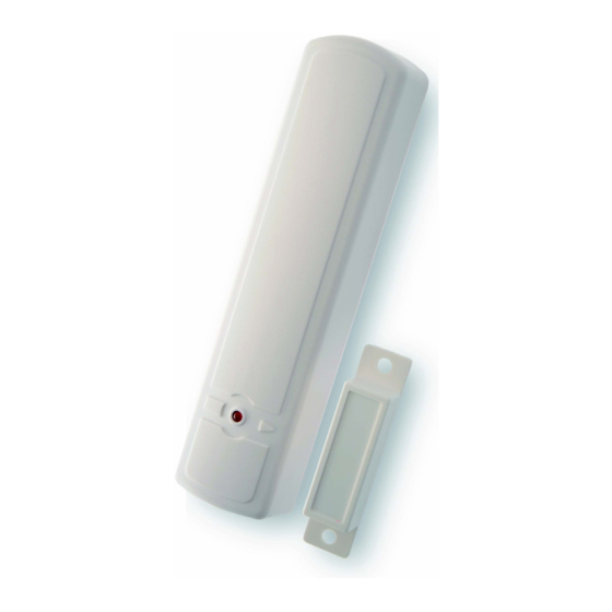
DOOR CONTACT (DC200)
CONTACT D'OVERTURE (DC200)
MAGNETNI KONTAKT (DC200)
Learn / Test button
Extension Terminal
Jumper Off
If the jumper link is removed or "parked" on one pin.
1/8
DS80MM80-001A
LBT80625
Publicité

Sommaire des Matières pour Elkron DC200
- Page 4 Toutefois, lorsque le détecteur est en mode test, le voyant clignote à chaque activation. PILE Le DC200 utilise deux piles alcalines « AAA » de 1,5 2 V d'une durée de vie supérieure à 2 ans avec une moyenne de 50 activations par jour.
- Page 5 All manuals and user guides at all-guides.com INSTALLATION Étape 1. Vérifiez que le cavalier du mode test/normal est en position « ON ». Ainsi, le voyant clignote à chaque opération du détecteur de porte. Étape 2. Fixez la base sur l'encadrement d’ouverture avec l'adhésif double face ou les vis fournies. Étape 3.


