Table des Matières
Publicité
Les langues disponibles
Les langues disponibles
Liens rapides
Publicité
Table des Matières

Sommaire des Matières pour salmson ALTI-V ELINOX-V 36
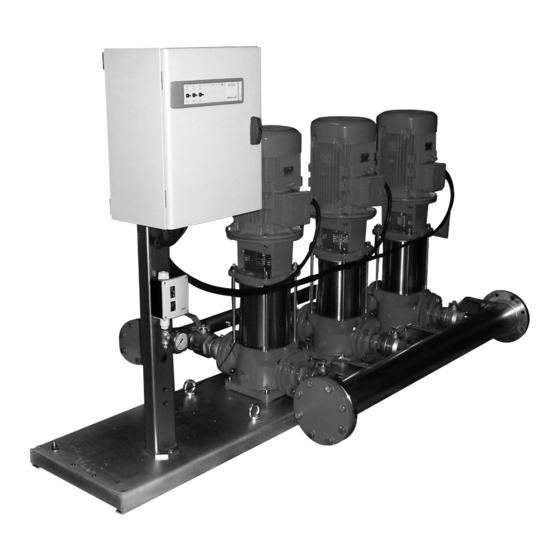
- Page 1 ALTI-V - ELINOX-V 36-60-80 INSTALLATION ET MISE EN SERVICE FRANCAIS DES MODULES DE SURPRESSION ALTI-V ET ELINOX-V INSTALLATION AND STARTING INSTRUCTIONS ENGLISH FOR ALTI-V AND ELINOX-V BOOSTER MODULES N.M.S. STOCK N° 4.094.405/Ed.3/03-08...
- Page 3 EK NOSAC JUMIEM uvedené v tomto prohlášení odpovídají ustanovením níže vastavustunnistuses kirjeldatud tooted on kooskõlas Uz mums «Pompes SALMSON» deklar , ka izstr d jumi, uvedených sm rnic a národním právním p edpis m, které je alljärgnevate direktiivide sätetega ning riiklike kas ir nosaukti šaj deklar cij , atbilst šeit uzskait to...
- Page 4 FIG. 1 FIG. 2 FIG. 3 FIG. 4 pression arrêt pression arrêt off pressure off pressure...
- Page 5 FIG. 5 bars PRESSION bars FIG. 6...
-
Page 6: Généralités
FRANCAIS 1. GÉNÉRALITÉS nominale plaquée sur les moteurs. • Sectionneur extérieur (verrouillable) de sécurité et de mise sous 1.1 Application tension du module. Le surpresseur a pour fonction essentielle d'assurer la mise et le main- • Fermeture par serrure à clé. tien sous pression d'un réseau de distribution d'eau à... - Page 7 FRANCAIS - voyant marche par pompe. avec fixation par boulons de scellement. Prévoir sous le massif en - Commutateur par pompe à 3 positions : béton un matériau isolant (liège ou caoutchouc armé) afin d'éviter AUTO - 0 - MANU (fugitif) toute transmission de bruit de circulation d'eau.
-
Page 8: Mise En Route
FRANCAIS flotteur à la main de façon à provoquer l'allumage du voyant COMMANDE AVEC AUTOMATE manque d'eau sur le coffret. S'assurer que l'appareil est "en eau". Reports En fonction des caractéristiques de l'installation, un report Mettre le commutateur des pompes en position "O". d'information peut-être nécessaire, un contact sec non alimenté... - Page 9 FRANCAIS 6.5 Réglages 6.5.2 Commande électronique 2 pompes (Voir FIG. 4) Réglage du pressostat de commande automatique Principe : Le réglage s'effectue en agissant sur l'écrou (rep. 1) pour obtenir le 6.5.1 Commande automate et électronique 3 pompes (Voir FIG. 3) point haut (arrêt de la pompe) et sur l'écrou (rep.
- Page 10 FRANCAIS 3 pompes 2 • Temporisation Marche I, Marche II, et Marche III de démarrage Les surpresseurs 3 pompes commande électronique fonctionnent des pompes 1, 2, 3 avec un pressostat automatique identique à une version automate Réglage en fonction de l’installation. (Voir paragraphe 6.5.1 pour les réglages).
-
Page 11: Mise En Service
FRANCAIS 6.6 Mise en service La pression de service maxi dans l'installation est ATTENTION ! égale à la pression à débit nul des pompes majo- rée le cas échéant de la pression d'eau de ville à l'entrée du sur- presseur. Sur le coffret, positionner le sectionneur général sur "I"... -
Page 12: Incidents De Fonctionnement
8. INCIDENTS DE FONCTIONNEMENT Si un incident de fonctionnement venait à persister, nous vous recommandons de vous adresser au SAV SALMSON, seuls habilités pendant la période de garantie à procéder au démontage-remontage de nos matériels. Avant toute intervention METTRE HORS TENSION le module. -
Page 13: Technical Characteristics
ENGLISH 1. GÉNÉRAL • Outside module safety and power switch (can be locked). • Closed by key lock. Application • The essential role of the booster is to pressurize a water distribution On front (see Fig. 2a) network in which the pressure is too low or non-existent. - ON indicator light - Dry-running indicator ALTI-V for clear, non-aggressive liquids (drinking water, glycolated... - Page 14 ENGLISH On front (see Fig. 2a) 5.2 Installation Install on a smooth, level floor, or on a concrete foundation block with 1- ON indicator light attachment by anchor bolts. Place an insulating material (cork or - Dry-running indicator reinforced rubber) under the concrete block to prevent any trans- - Fault indicator (one per pump) mission of flowing-water noise.
-
Page 15: Check Of Direction Of Rotation
ENGLISH Remoting AUTOMAT CONTROL Depending on the characteristics of the installation, a signal may Make sure that the equipment contains water. have to be remoted. A dry voltage-free contact closing on faults is provided for this purpose (general fault remoting): Automat version, terminals 6 and 13, max. - Page 16 ENGLISH 6.5 Adjustments 6.5.2 Electronic control 2 pumps (see Fig. 4) Principle: Adjustment of automatic control pressure switch The adjustment is made by turning the nut (item 1) to set the high point (stopping of pump) and the nut (item 2) to adjust the low 6.5.1 Automat and electronic control of 3 pumps point (starting of pump).
- Page 17 ENGLISH 3 pumps Come back pressure I = 5” The 3-pump boosters with electronic control use the same automa- Come back pessure II = 15” tic control pressure switch as an automat version (see paragraph 2 • Timer Start I, Start II, and Start III starting of pumps 1, 2, 3 6.5.1 for the adjustments).
- Page 18 ENGLISH 6.6 Starting up The maximum service pressure in the installation is equal to the zero-flow pressure of the pumps plus ATTENTION ! any town water pressure at the booster inlet. On the box, set the general disconnecting switch to "I" and the selec- tor switches of the pumps to "Auto".
-
Page 19: Operating Trouble
ENGLISH 8. OPERATING TROUBLE Before any action, POWER DOWN the module. TROUBLE CAUSE REMEDIAL ACTION 8.1 One or two pumps a) Air leak at suction. a) Check the tightness of all suction piping connections. fail to prime. Check if the suction strainer (Version "B") is correctly covered with water. b) Foot valve-strainer (Version "B") not tight or b) Check the tightness of the check valve;... -
Page 20: Service Consommateur
THIS LEAFLET HAS TO BE GIVEN TO THE END USER AND MUST BE LEFT ON SITE. SALMSON VIETNAM W.S.L. LEBANON SALMSON ARGENTINA S.A. E-TOWN - Unit 3-1C Bou Khater building - Mazda Center Av. Montes de Oca 1771/75 364 CONG HOA - TAN BINH Dist.


