Table des Matières
Publicité
Les langues disponibles
Les langues disponibles
Liens rapides
Features
• Assembled in USA
• 0-90 second field replaceable time delay retard
• Easy to read retard time delay adjustment knob
• Fits 1" to 2" CPVC, copper, brass, or iron pipe
• Comes with all necessary paddles
• Two SPDT (form C) contacts
• Weatherproof
• Easy to read wire terminal designations
• 5 year warranty
CAUTION
Waterflow switches that are monitoring wet pipe sprinkler systems
shall not be used as the sole initiating device to discharge AFFF,
deluge, or chemical suppression systems. Waterflow switches used
for this application may result in unintended discharges caused by
surges, trapped air, or short retard times.
Important: This document contains important information on the installation and operation of the VSR-S waterflow switches. Please read all instructions
carefully before beginning installation. A copy of this document is required by NFPA 72 to be maintained on site.
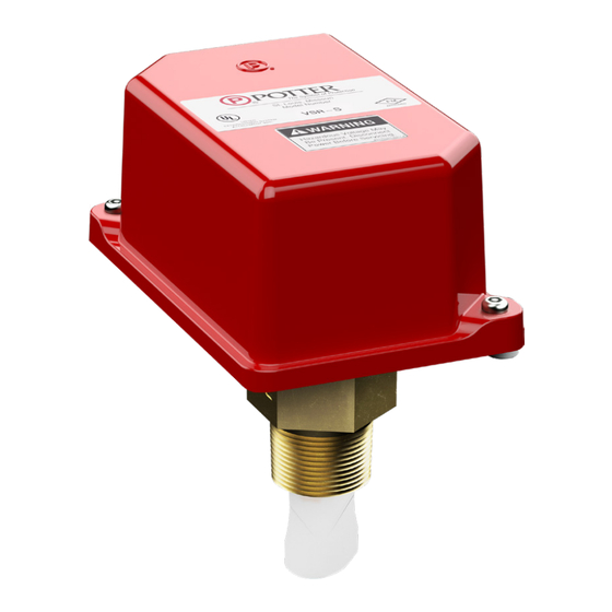
Description
The Model VSR-S is a vane type waterflow switch for use on wet
sprinkler systems that use 1" (25mm), 1¼" (32mm), 1½" (38mm) or 2"
(50mm) pipe size. The unit may also be used as a sectional waterflow
detector on large systems.
The unit contains two single pole double throw snap action switches
and an adjustable, instantly recycling pneumatic retard. The switches
are actuated when a flow of 10 gallons per minute (38 LPM) or more
occurs downstream of the device. The flow condition must exist for a
period of time necessary to overcome the selected retard period.
Enclosure
The VSR-S switches and retard device are enclosed in a weather/UV/
flame resistant high impact composite plastic. The cover is held in
place with two tamper resistant screws which require a special key
for removal. A field installable cover tamper switch is available as an
option which may be used to indicate unauthorized removal of the
cover. See bulletin number 5401103 for installation instructions of this
switch.
•
Installation must be performed by qualified personnel
and in accordance with all national and local codes and
ordinances.
•
Shock hazard. Disconnect power source before servicing.
Serious injury or death could result.
•
Risk of explosion. Not for use in hazardous locations. Serious
injury or death could result.
Potter Electric Signal Company, LLC
Technical Specifications
Service Pressure
Flow Required for
Alarm
Maximum Surge
Enclosure
Contact Ratings
Conduit Entrances
Usage
Environmental
Specifications
Service Use
*Specifications subject to change without notice.
•
St. Louis, MO
•
•
5401207 - REV J
11/21
Vane Type Waterflow Alarm
Switch With Retard
300 PSI (20,68 BAR) - UL
10 GPM (38 LPM)
To ensure minimum flow of 10 gpm, a minimum pressure is
required at all sprinklers with a k-factor of 3 or less.
K-3: 10 PSI
K-2.8: 12 PSI
18 FPS (5,5 m/s)
Cover - Weather/UV/Flame Resistant High Impact Composite
Base - Die-cast aluminum
Two sets of SPDT (Form C)
10.0 Amps at 125/250VAC
2.0 Amps at 30VDC Resistive
10 mAmps min. at 24VDC
Two 1/2" conduit connections provided. Individual switch
compartments suitable for dissimilar voltages.
Listed plastic, copper, schedule 40 iron pipe and unlisted riser
assemblies approved by Potter .
Fits pipe sizes - 1", 1¼", 1½" and 2"
Note:
12 paddles are furnished with each unit, one for each pipe
size of threaded and sweat TEE, one for 1" CPVC, one for 1"
CPVC (Central), one for 1" threaded Nibco CPVC, and one for
1½" threaded (Japan).
• NEMA 4/IP54 Rated Enclosure suitable for indoor or
outdoor use with factory installed gasket when used with
appropriate conduit fitting.
• Temperature Range: 40°F - 120°F, (4.5°C - 49°C) - UL
Automatic Sprinkler
One or two family dwelling
Residential occupancy up to four stories
National Fire Alarm Code
Phone: 800-325-3936
VSR-S
NFPA-13
NFPA-13D
NFPA-13R
NFPA-72
•
www.pottersignal.com
PAGE 1 OF 6
Publicité
Table des Matières

Manuels Connexes pour Potter VSR-S


Sommaire des Matières pour Potter VSR-S
- Page 1 Important: This document contains important information on the installation and operation of the VSR-S waterflow switches. Please read all instructions carefully before beginning installation. A copy of this document is required by NFPA 72 to be maintained on site.
- Page 2 If an alarm is not desired, a Flowswitch Bypass Switch should be used (refer to Potter data sheet 5401554), or a qualified technician should disable the alarm system.
- Page 3 Fig. 3 and have been factory approved by Potter. Apply teflon tape to the 1” NPT fitting. Do not use more than three wraps of teflon tape.
- Page 4 The terminals can also be used to connect to a fire/security panel. Notes: 1. The Model VSR-S has two switches, one can be used to operate a central station, proprietary or remote signaling unit, while the other contact is used to operate a local audible or visual annunciator.
-
Page 5: Mounting Dimensions
DWG# 1206-5 Inspect detectors monthly for leaks. If leaks are found, replace the detector. The VSR-S waterflow switch should provide years of trouble-free service. The retard and switch assembly are easily field replaceable. In the unlikely event that either component does not perform properly, please order replacement retard switch assembly stock number 1029030. -
Page 6: Ordering Information
• Lift detector clear of pipe. FSBS - Flowswitch Bypass Switch , stock no. 3001006 DG-B-R Surface Mount Double Gang Box - Red F/ FSBS, stock no. 1000484 Potter Electric Signal Company, LLC • St. Louis, MO • Phone: 800-325-3936 •... -
Page 7: Caractéristiques
Important : Ce document contient d’importantes informations à propos de l’installation et du fonctionnement des commutateurs de débit VSR-S. Veuillez lire toutes les instructions attentivement avant de commencer à installer ces dispositifs. Conformément à la NFPA 72, une copie de ce document doit être conservée sur le site. -
Page 8: Montage
Si une alarme n’est pas souhaitée, un commutateur de débit/sectionneur de dérivation (FSBS) doit être utilisé (voir la fiche technique Potter nº 5401554), ou un technicien qualifié... -
Page 9: Câblage Du Commutateur À Protection Antimanipulation
3 et qu’ils aient été approuvés en usine par Potter. Appliquez du ruban téflon sur le raccord NPT de 1 po (25 mm). Ne pas appliquer plus de trois couches de ruban téflon. -
Page 10: Raccordements Électriques Types
Remarques : 1. Le modèle VSR-S a deux commutateurs, l’un peut être utilisé pour faire fonctionner une station centrale, une unité de signalisation propriétaire ou à distance, tandis que l’autre contact est utilisé pour faire fonctionner un annonciateur sonore ou visuel local. -
Page 11: Dimensions De Montage
DWG# 1206-5 Inspectez les détecteurs tous les mois pour détecter les fuites. Si des fuites sont détectées, remplacez le détecteur. Le commutateur de débit d’eau VSR-S devrait fournir des années de service sans problème. L’ensemble retardateur/commutateur est facilement remplaçable sur site. Dans le cas peu probable où l’un ou l’autre des composants ne fonctionnerait pas correctement, veuillez commander l’ensemble retardateur/commutateur de remplacement nº... -
Page 12: Remplacement De L'ensemble Retardateur/Commutateur
FSBS - commutateur de débit/sectionneur de d’eau. dérivation (réf. 3001006) Boîte à double commande montage en surface DG- • Soulevez le détecteur du tuyau. B-R - Rouge F/ FSBS (réf. 1000484) Potter Electric Signal Company, LLC • St. Louis, MO • Téléphone : 800-325-3936 •...