Table des Matières
Publicité
Les langues disponibles
Les langues disponibles
Liens rapides
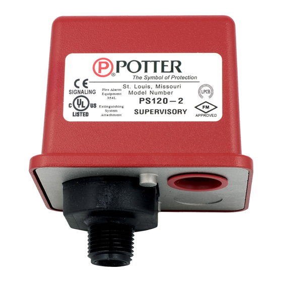
Features
• One or two switch models available
• Independent switch adjustment on two switch models, no tools
needed
• Two 1/2" conduit/cable entrances
• Separate isolated wiring chambers
• Non-corrosive pressure connection
• VdS version available
• Non-Conductive enclosure
• Available with Nylon or Brass pressure connection (Nylon
connection shown in picture).
This document contains important information on the installation
and operation of PS120 pressure switches. Please read all instructions
carefully before beginning installation. A copy of this document is
required by NFPA 72 to be maintained on site.
Installation
The Potter PS120 Series Supervisory Pressure Actuated Switches
are designed primarily to detect an increase and/or decrease from
normal system pressure in automatic fire sprinkler systems. Typical
applications are: Wet pipe systems with excess pressure, pressure
tanks, air supplies, water supplies, and monitoring pressure regulators
in standpipes. The PS120 switch is factory set for 120 psi (8,3 bar)
normal system pressure. The switch marked with the word LOW is set
to operate at a pressure decrease of 10 psi (0,7 bar) at 110 psi (7,6 bar).
The switch marked with the word HIGH is set to operate at a pressure
increase of 10 psi (0,7 bar) at 130 psi (9 bar). See section heading
Adjustments and Testing if other than factory set point is required.
1.
Connect the PS120 to the system side of any shutoff or check valve.
2.
Apply Teflon tape to the threaded male connection on the device.
(Do not use pipe dope)
3.
Device should be mounted in the upright position.
(Threaded connection down)
4.
Tighten the device using a wrench on the flats on the device.
Potter Electric Signal Company, LLC
Technical Specifications
Conduit Entrances
Contact Ratings
Cover Tamper
Differential
Dimensions
Enclosure
Environmental
Limitations
Factory Adjustment
Maximum System
Pressure
Pressure Connection
Pressure Range
Service Use
*Specifications subject to change without notice.
•
St. Louis, MO
•
•
5400934 - REV K
9/21
firealarmresources.com
PS120 Series
Supervisory Pressure Switch
Two knockouts for 1/2" conduit provided. Individual switch
compartments and ground screw suitable for dissimilar voltages
SPDT (Form C)
10.1 Amps at 125/250VAC, 2.0 Amps at 30VDC
One SPDT in PS120-1, Two SPDT in PS120-2
Cover incorporates tamper resistant fastener that requires a special
key for removal. One key is supplied with each device.
Typical 2 lbs at 35 psi (0,14 at 2,41 bar)
9 lbs at 225 psi (0,62 at 15,51 bar)
3.78"(9,6cm)Wx3.20"(8,1cm)Dx4.22"(10,7cm)H
Cover: Weather/UV/Flame Resistant High Impact Composite
Base: Die Cast
All parts have corrosion resistant finishes
-40º F to 140ºF (-40ºC to 60ºC)
NEMA 4/IP66 Rated Enclosure indoor or outdoor when used with
NEMA 4 conduit fittings
PS120-1 operates on decrease at 110 psi (7,6 bar)
PS120-2 operates in increase at 130 psi (9 bar) and on decrease
at 110 psi (7,6 bar)
300 psi (20,68 bar)
1/2" NPT male Nylon or optional Brass
35-225 psi (2,41 to 15,51 bar)
NFPA 13, 13D, 13R, 14, 72
Phone: 800-325-3936
•
www.pottersignal.com
PAGE 1 OF 8
Publicité
Table des Matières

Sommaire des Matières pour Potter PS120 Serie
- Page 1 NFPA 72 to be maintained on site. Installation Technical Specifications The Potter PS120 Series Supervisory Pressure Actuated Switches Two knockouts for 1/2” conduit provided. Individual switch Conduit Entrances are designed primarily to detect an increase and/or decrease from compartments and ground screw suitable for dissimilar voltages normal system pressure in automatic fire sprinkler systems.
-
Page 2: Wiring Instructions
Testing the PS120 may activate other system connected devices. thereby providing supervision of the connection in the event that the wire The use of a Potter BVL (see product bulletin 8900067 for details) is becomes dislodged from under the terminal. -
Page 3: Typical Connections
DWG# 928-2 Closed under normal under normal system DWG# 930-3 system pressure. pressure. Closes on pressure drop. Use for low pressure signal. Potter Electric Signal Company, LLC • St. Louis, MO • Phone: 800-325-3936 • www.pottersignal.com • 5400934 - REV K... -
Page 4: Ordering Information
Description Part Number connected into the air supply line on the system side of any shut-off valve. Pressure switch with one set SPDT A Model BVL bleeder valve as supplied by Potter Electric Signal Company PS120-1 1341205 contacts of St. Louis, MO., or equivalent shall be connected in line with the PS120 to Pressure switch with two sets SPDT provide a means of testing the operation of the supervisory switch. -
Page 5: Caractéristiques
Les commutateurs de surveillance actionnés par pression de la série Le dispositif est muni de deux entrées défonçables pour des conduits PS120 de Potter ont été conçus principalement pour détecter une Entrée des conduits de 1/2". Des compartiments individuels pour chaque commutateur et des vis de terre adaptées en cas de tensions différentes ont été... - Page 6 L’utilisation d’un robinet de purge coupé afin de contrôler la connexion en cas d’éventuel détachement du câble BVL Potter (voir la fiche produit 8900067) est recommandée afin de de sous la borne. faciliter les procédures de réglage et d’essai du commutateur de pression PS120.
-
Page 7: Variation De Pression
Se ferme en cas de chute de signal de pression haute. DWG# 930-3 pression. Permet de détecter un Fermé avec une pression signal de pression faible. normale du système. Potter Electric Signal Company, LLC • St. Louis, MO • Phone: 800-325-3936 • www.pottersignal.com •... -
Page 8: Spécifications Ingénieur/Architecte Du Commutateur De Débit À Pression
à pression. de ½ po à brancher sur la ligne d’alimentation en air du côté système Renseignements pour passer commande d’une vanne d’arrêt. Un robinet de purge, tel que le modèle BVL de Potter Electric Modèle Description Numéro de Signal Company, St.


