Table des Matières
Publicité
Les langues disponibles
Les langues disponibles
Liens rapides
R
Features
• Assembled in USA
• 0-90 second field replaceable time delay retard
• Easy to read retard time delay adjustment knob
• UL Listed models for 2"-6" steel pipe schedules 5 through 40
• UL Listed and FM approved models for 2"-8" steel pipe schedules
10 through 40
• Two SPDT (form C) contacts
• Weatherproof
• Easy to read wire terminal designations
• Installation must be performed by qualified personnel and in
accordance with all national and local codes and ordinances.
• Shock hazard. Disconnect power source before servicing. Serious
injury or death could result.
• Risk of explosion. Not for use in hazardous locations. Serious
injury or death could result.
Waterflow switches that are monitoring wet pipe sprinkler systems shall
not be used as the sole initiating device to discharge AFFF, deluge,
or chemical suppression systems. Waterflow switches used for this
application may result in unintended discharges caused by surges,
trapped air, or short retard times.
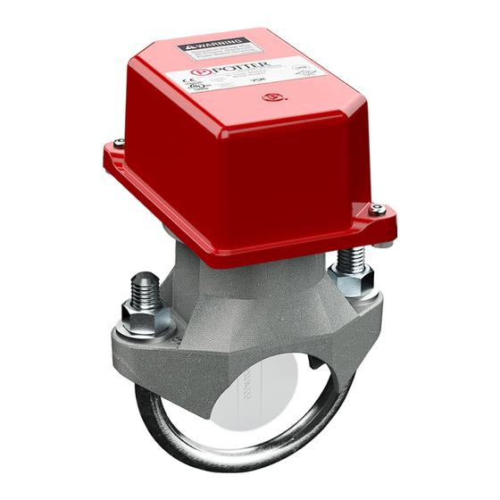
Description
The Model VSR is a vane type waterflow switch for use on wet
sprinkler systems. It is UL Listed for use on a steel pipe; schedules 5
through 40, sizes 2" - 6" and is UL Listed and FM Approved for use on
steel pipe; schedules 10 through 40, sizes 2" thru 8" (50 mm thru 200
mm). LPC approved sizes are 2" thru 8" (50 mm thru 200 mm). See
Ordering Information chart.
The VSR may also be used as a sectional waterflow detector on large
systems. The VSR contains two single pole, double throw, snap action
switches and an adjustable, instantly recycling pneumatic retard. The
switches are actuated when a flow of 10 GPM (38 LPM) or more
occurs downstream of the device. The flow condition must exist for a
period of time necessary to overcome the selected retard period.
Enclosure
The VSR switches and retard device are enclosed in a weather/UV/
flame resistant high impact composite plastic. The cover is held in
place with two tamper resistant screws which require a special key
for removal. A field installable cover tamper switch is available as
an option which may be used to indicate unauthorized removal of the
cover. See bulletin number 5401103 for installation instructions of
this switch.
NOTICE
This document contains important information on the installation
and operation of the VSR. Please read all instructions carefully and
notify the building owner or their authorized representative before
any work is done on the fire sprinkler or fire alarm system. A copy
of this document is required by NFPA 72 to be maintained on site.
Potter Electric Signal Company, LLC
Vane Type Waterflow Alarm Switch W/ Retard
Technical Specifications
Conduit
Entrances
Contact
Ratings
Enclosure
Environmental
Specifications
Flow
Sensitivity
Range for
Signal
Maximum
Surge
Service
Pressure
Service Use
Specifications subject to change without notice.
•
St. Louis, MO
•
•
5401151 - REV K
10/21
Two knockouts provided for 1/2" conduit. Individual
switch compartments suitable for dissimilar voltages
Two sets of SPDT (Form C)
10.0 Amps at 125/250VAC
2.0 Amps at 30VDC Resistive
10 mAmps min. at 24VDC
Cover - Weather/UV/Flame Resistant High Impact
Composite
Base - Die-cast aluminum
NEMA 4/IP54 Rated Enclosure suitable for indoor or
outdoor use with factory installed gasket when used with
appropriate conduit fitting.
Temperature Range: 40°F - 120°F, (4.5°C - 49°C) - UL
Non-corrosive sleeve factory installed in saddle.
4-10 GPM (15-38 LPM) - UL
18 FPS (5.5 m/s)
450 PSI (31 BAR) - UL
Automatic Sprinkler
One or two family dwelling
Residential occupancy up to four stories NFPA-13R
National Fire Alarm Code
Phone: 800-325-3936
VSR
NFPA-13
NFPA-13D
NFPA-72
•
www.pottersignal.com
PAGE 1 OF 5
Publicité
Table des Matières

Manuels Connexes pour Potter VSR


Sommaire des Matières pour Potter VSR
- Page 1 Description Technical Specifications The Model VSR is a vane type waterflow switch for use on wet Two knockouts provided for 1/2" conduit. Individual sprinkler systems. It is UL Listed for use on a steel pipe; schedules 5...
- Page 2 0.134 3.40 0.280 7.11 0.197 0.157 VSR-8 DN200 8.625 219.1 0.148 3.76 0.322 8.18 0.248 0.177 Potter Electric Signal Company, LLC • St. Louis, MO • Phone: 800-325-3936 • www.pottersignal.com • 5401151 - REV K 10/21 PAGE 2 OF 5...
- Page 3 Testing The frequency of inspection and testing for the Model VSR and its associated protective monitoring system shall be in accordance with applicable NFPA Codes and Standards and/or the authority having jurisdiction (manufacturer recommends quarterly or more frequently).
- Page 4 Maintenance Inspect detectors monthly. If leaks are found, replace the detector. The VSR waterflow switch should provide years of trouble-free service. The retard and switch assembly are easily field replaceable. In the unlikely event that either component does not perform properly, please order replacement retard switch assembly stock #1029030 (see Fig.
-
Page 5: Ordering Information
VSR-8 8" DN200 1144408 Optional: Cover Tamper Switch Kit, stock no. 0090148 FSBS-FLOWSWITCH BYPASS SWITCH, stock no. 3001006 Replaceable Components: Retard/Switch Assembly, stock no. 1029030 Potter Electric Signal Company, LLC • St. Louis, MO • Phone: 800-325-3936 • www.pottersignal.com •... -
Page 6: Caractéristiques
Description Spécifications techniques Le modèle VSR est un commutateur de débit d’eau à ailettes à utiliser sur les systèmes Le dispositif est muni de deux entrées défonçables pour de gicleurs sous eau. Il est homologué UL pour une utilisation sur un tuyau en acier ;... -
Page 7: Commutateur D'alarme De Débit À Ailettes Avec Retardateur
3,40 0,280 7,11 0,197 0,157 VSR-8 DN200 8,625 219,1 0,148 3,76 0,322 8,18 0,248 0,177 Potter Electric Signal Company, LLC • St. Louis, MO • Téléphone : 800-325-3936 • www.pottersignal.com • 5401151 - RÉV. K 10/21 PAGE 2 SUR 5... -
Page 8: Connexions Des Bornes Du Commutateur
Vérification La fréquence d’inspection et de vérification du modèle VSR et de son système de surveillance de protection associé doit être conforme aux codes et normes NFPA applicables et/ou à l’autorité compétente (le fabricant recommande une fréquence trimestrielle ou plus). -
Page 9: Entretien
Entretien Inspectez les détecteurs tous les mois. Si des fuites sont détectées, remplacez le détecteur. Le commutateur de débit d’eau du VSR devrait fournir des années de service sans problème. L’ensemble retardateur/commutateur est facilement remplaçable sur site. Dans le cas peu probable où l’un ou l’autre des composants ne fonctionnerait pas correctement, veuillez commander l’ensemble retardateur/commutateur de remplacement nº... -
Page 10: Retrait Du Commutateur De Débit D'eau
1144408 En option : trousse de protection antimanipulation (réf. 0090148) FSBS - COMMUTATEUR DE DÉBIT/SECTIONNEUR DE DÉRIVATION (réf. 3001006) Pièces remplaçables : ensemble retardateur/commutateur (réf. 1029030) Potter Electric Signal Company, LLC • St. Louis, MO • Téléphone : 800-325-3936 •...