Table des Matières
Publicité
Les langues disponibles
Les langues disponibles
Liens rapides
Bedieningshandleiding en
installatieinstructies
Operation manual and
installation instructions
Bedienungshandbuch und
Einbauanleitung
Manuel d'utilisation et
instructions d'installation
Manual de manejo y
instrucciones de instalación
Manuale per l'uso e
istruzioni per l'installazione
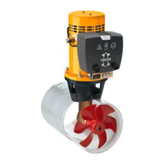
80 kgf
ø 185 mm
C o p y r i g h t © 2 0 0 1 Ve t u s d e n O u d e n n . v. S c h i e d a m H o l l a n d
Publicité
Table des Matières

Manuels Connexes pour Vetus BOW8012


Sommaire des Matières pour Vetus BOW8012
- Page 1 Bedieningshandleiding en installatieinstructies Operation manual and installation instructions Bedienungshandbuch und Einbauanleitung Manuel d’utilisation et instructions d’installation Manual de manejo y instrucciones de instalación Manuale per l’uso e istruzioni per l’installazione 80 kgf ø 185 mm C o p y r i g h t © 2 0 0 1 Ve t u s d e n O u d e n n . v. S c h i e d a m H o l l a n d...
-
Page 2: Table Des Matières
Inhoud Contents Inleiding Introduction Veiligheid Safety Gebruik Installatieinstructies Installation instructions Installatie aanbevelingen Installation recommendations Inbouw Installation Stroomverzorging The power supply Elektrische installatie Electrical installation Onderhoud Maintenance Storingen Trouble shooting Technische gegevens Technical data Inbouwvoorbeelden Installation examples Elektrisch schema Wiring diagram Hoofdafmetingen Principal dimensions Inhalt... -
Page 3: Inleiding
NEDERLANDS Inleiding Veiligheid Afhankelijk van de windvang, de waterverplaatsing en de vorm van het onderwaterschip zal de door de boegschroef geleverde WAARSCHUWING! stuwkracht op ieder schip een verschillend resultaat geven. Let bij het gebruik van de boegschroef op het gevaar voor zwemmers of lichte bootjes welke zich in de onmiddelijke De nominaal opgegeven stuwkracht is alleen haalbaar onder nabijheid van de boegschroefbuis-uitstroomopeningen... -
Page 4: Installatieinstructies
Deze installatie instructie geeft richtlijnen voor de inbouw van de Vetus boegschroeven ‘BOW8012’ en ‘BOW8024’. Bij het kiezen van de positie waar de tunnel- De kwaliteit van de inbouw is maatgevend voor de betrouw-... -
Page 5: Overgang Van Tunnelbuis Naar Scheepsromp
NEDERLANDS Overgang van tunnelbuis naar scheepsromp Indien de overgang van tunnel- buis op scheepsromp met een schuine zijde wordt uitgevoerd dient deze volgens de tekening De wijze waarop de tunnelbuis overgaat in de scheeps- te worden uitgevoerd. romp is van grote invloed op de door de boegschroef Maak de schuine zijde (C) 0,1 à... -
Page 6: Inbouw
Bij een stalen of aluminium tunnelbuis kan vermindering Polyester tunnelbuis: van corrosie worden bereikt Hars: Het voor de polyester tunnelbuis toegepaste hars is door het volledig geïsoleerd isophtaalzure polyesterhars (Norpol PI 2857). opstellen van het staartstuk Voorbehandeling: De buitenzijde van de buis moet wor- in de tunnelbuis. -
Page 7: Montage Staartstuk En Tussenflens
NEDERLANDS Montage staartstuk en tussenflens Eindmontage Verwijder de schroef. Vet de schroefas in met ‘out- board gear grease’ en mon- teer de schroef. Breng de pakking aan tussen staartstuk en tunnelbuis, pas hierbij -tussen staartstuk en pakking- een afdichtmiddel (polyurethaan* of siliconen) toe, en plaats het staartstuk in het gat in de tunnelbuis. -
Page 8: Stroomverzorging
‘Installatieinstructies’. Bij toe- Wij bevelen Vetus onderhoudsvrije scheepsaccu’s aan; welke passing van aanzienlijke grotere accu’s in combinatie leverbaar zijn in de navolgende grootten : 55 Ah, 70 Ah, 108 Ah, met zeer korte accuaansluitkabels met een aanzien- 143 Ah en 165 Ah. -
Page 9: Elektrische Installatie
Electrische installatie op het eerste paneel worden aangesloten. Controleer of de spanning, vermeld op het typeplaatje van de Raadpleeg Vetus den Ouden N.V. indien, in plaats van een motor, overeenkomt met de boordspanning. Vetus bedieningspaneel, twee aparte schakelaars worden toe- Plaats de accu of accu’s zo dicht mogelijk bij de boegschroef;... -
Page 10: Onderhoud
BP238 Voor accu-onderhoud dienen de instructies van de acculever- Raadpleeg Vetus voor andere motortypen dan bovengenoemd. ancier te worden geraadpleegd. VETUS accu’s zijn onder- houdsvrij. 2.0525 Bedieningshandleiding en installatieinstructies Boegschroef 80 kgf, ø 185 mm... -
Page 11: Storingen
Electromotor draait (te) snel, maar er is geen stuw- ) Boegschroef Zekering: ‘traag’ Art. code kracht BOW8012 (12 V) 355 A ZE 355 - Breekpen gebroken ten gevolge van een voorwerp in de BOW8024 (24 V) 160 A ZE 160 schroef of tunnelbuis. -
Page 12: Technische Gegevens
Technische gegevens Type BOW8012 BOW8024 Electromotor Type omkeerbare gelijkstroommotor Spanning 12 V = 24 V = Stroom 580 A 280 A Afgegeven vermogen 4,7 kW Toerental 3600 omw/min Inschakelduur S2 - 3 min. S2 - 4 min. Bescherming IP20 Motoren zijn conform CE (89/336/EEC, EMC - EN60945) - Page 13 ENGLISH Introduction Safety The thrust given by the bow thruster will vary from vessel to ves- sel depending on the effect of the wind, the water displacement WARNING! and the shape of the underwater hull. When using the bow thruster watch out for swimmers or light boats which could be in the near vicinity of the bow The nominal thrust quoted can only be achieved under the most thruster tunnel jet openings.
-
Page 14: Installation Instructions
These installation instructions give guidelines for fitting the account for optimum per- Vetus bow thrusters ‘BOW8012’ and ‘BOW8024’. formance: • The distance A shown The standard of fitting determines the reliability of the bow in the drawing must thruster. -
Page 15: Connection Of Thrust Tunnel To Ship's Hull
ENGLISH Connection of thrust tunnel to ship’s hull If the connection of the thrust tunnel and the ship’s hull is to be made with a sloped side, it should be executed in accor- The manner, in which the thrust tunnel is connected to the dance with the drawing. -
Page 16: Installation Of The Thrust Tunnel
Corrosion of a steel or alu- minium thrust tunnel can be Polyester thrust tunnel: reduced by ensuring that Resin: The resin used for the polyester thrust tunnel is the tail piece is completely Isophtalic polyester resin (Norpol Pl 2857). insulated from the thrust- Pre-treatment: The outside of the tunnel must be rough- tunnel. -
Page 17: Final Assembly
ENGLISH Installation of tail piece and intermediate Final assembly flange Remove the propeller. Grease the propeller shaft with ‘outboard gear grease’ and install the propeller. Install the gasket between the tail piece and the thrust tunnel. Apply sealant (polyurethane* or silicon) between the tail piece and the gasket and between the The propeller should run a... -
Page 18: The Power Supply
10% of the volt- age supplied; see the table. A main switch and fuse must be fitted in the ‘plus’ cable. A Vetus battery switch is suitable here. The fuse protects the bow thruster against overvoltage and at the same time protects the vessel’s wiring against short-circuits. -
Page 19: Electrical Installation
Vetus bow thruster, Vetus art. code: BPSP . If the batteries connected installed for the bow thruster are also to be used for other (12 together. - Page 20 The instructions of the manufacturer should be followed for the maintenance of the batteries. Vetus batteries are maintenance BP238 free. Consult with Vetus for motor types other than those given here. 2.0525 Operation manual and installation instructions Bow thruster 80 kgf, ø 185 mm...
- Page 21 ) Bow thruster Fuse: ‘slow blow’ Art. code Electric motor turns (too) fast but there is no thrust BOW8012 (12 V) 355 A ZE 355 - Break pin broken because of an object in the propeller or BOW8024 (24 V)
-
Page 22: Technical Data
Technical data Type BOW8012 BOW8024 Electric motor Type reversible DC motor Voltage 12 V DC 24 V DC Current 580 A 280 A Rated output 4,7 kW No. of revolutions 3600 rpm Rating S2 - 3 min. S2 - 4 min. -
Page 23: Einleitung
DEUTSCH Einleitung Sicherheitsbestimmungen Je nach Takelage, Wasserverdrängung und Unterwasser- schifform führt die Antriebskraft durch die Bugschraube auf WARNUNG! jedem Schiff zu anderen Ergebnissen. Achten Sie bei Benutzung der Bugschraube auf die Gefahr für Schwimmer und kleine Boote, die sich in Die angegebene Nennantriebskraft ist nur unter optimalen unmittelbarer Nähe der Bugschraubenrohrausström- Umständen erreichbar:... -
Page 24: Einbauanleitung
Wir raten davon ab, 2 Bugschrauben in einem (1) Tunnelrohr einzu-bauen. Eine Verdoppelung der Antriebskraft wird dadurch nicht erreicht! Diese Einbauanleitung enthält Richtlinien für den Einbau der Vetus Bugschrauben ‘BOW8012’ und ‘BOW8024’. Bei der Platzbestimmung des Tunnelrohrs soll für Die Einbauqualität ist maßgeblich für die Zuverlässigkeit der bestmöglichen... -
Page 25: Übergang Vom Tunnelrohr Zum Schiffsrumpf
DEUTSCH Übergang vom tunnelrohr zum schiffsrumpf Wenn Übergang Tunnelrohr zum Schiffsrumpf abgeschrägter Seite versehen wird, so soll die Die Art und Weise worauf das Tunnelrohr zum Ausführung laut obenstehender Schiffsrumpf übergeht, beeinflusst sehr den von der Zeichnung durchgeführt Bugschraube gelieferten Schubkraft, sowie auch den werden. -
Page 26: Einbau
Korrosion eines Stahl- oder A l u m i n i u m -Tu n n e l r o h r s Polyester-Tunnelrohr: kann verringert werden Harz: Für das Polyester-Tunnelrohr wird isophtal-saures durch vollständig isolierte Polyesterharz (Norpol PI 2857) benutzt. Montage Vorbehandlung: Außenseite... -
Page 27: Befestigung Des Unterwasserteils Und Des Zwischenflansches
DEUTSCH Befestigung des Unterwasserteils und des Endmontage Zwischenflansches Entferne die Schraube. Schraubenwelle ‘outboard gear grease’ einfetten und die Schraube Dichtung zwischen montieren. Unterwasserteil Tunnelrohr anbringen. Dabei sowohl zwischen Unterwasserteil Dichtung zwischen Zwischen Tunnelrohrwand Dichtung und Tunnelrohr und Schraube muß sich nun eine Dichtungsmasse ringsherum... -
Page 28: Stromversorgung
Die Gesamtkapazität des Akkus muß auf die Größe der Akkuanschlußkabeln. Siehe Einbauanleitungen. Bei Bugschraube abgestimmt sein. Siehe Tabelle. Verwendung erheblich größerer Akkus in Kombination Wir empfehlen wartungsfreie Schiffsakkus von Vetus. Sie sind in mit sehr kurzen Akkuanschlußkabeln mit einem folgenden Größen lieferbar: erheblich größeren Durchschnitt als empfohlen nimmt 55 Ah, 70 Ah, 108 Ah, 143 Ah und 165 Ah. -
Page 29: Elektrische Installation
Spannung mit der Bordspannung übereinstimmt. Den Akku oder die Akkus so nah wie möglich bei der Ziehen Sie Vetus den Ouden N.V. zu Rate, wenn anstelle eines Bugschraube aufstellen, die Hauptstromkabel können dann Vetus Armaturenbretts zwei einzelne Schalter verwendet kurz sein, und der Spannungsverlust bleibt gering. -
Page 30: Wartung
Achse 16 mm min. einbauen. Akku-Wartung sind Anweisungen Akkulieferanten zu beachten. VETUS Akkus sind wartungsfrei. BP238 Bei anderen Motorentypen als oben angegeben ziehen Sie bitte Vetus zu Rate. 2.0525 Bedienungshandbuch und Einbauanleitung Bugschraube 80 kgf, ø 185 mm... -
Page 31: Störungen
Steuerstromsicherung befinden. Der Elektromotor läuft (zu) schnell, aber keine ) Bugschraube Sicherung: ‘träge’ Artikelnummer Antriebskraft vorhanden BOW8012 (12 V) 355 A ZE 355 - Wegen eines Gegenstands in der Schraube oder im BOW8024 (24 V) 160 A ZE 160 Tunnelrohr ist der Brechbolzen gebrochen. -
Page 32: Technische Daten
Technische daten BOW8012 BOW8024 Electromotor umkehrbarer Gleichstrommotor Spannung 12 V = 24 V = Strom 580 A 280 A Leistung 4,7 kW Drehzahl 3600 U/min Einschaltdauer S2 - 3 min. S2 - 4 min. Sicherung IP20 Motoren sind CE-konform (80/336/EEC, EMC - EN60945) Übertragung... - Page 33 FRANÇAIS Introduction Sécurité Selon la prise de vent, le déplacement d’eau et la forme des oeuvres vives, la force de propulsion fournie par l’hélice d’étra- AVERTISSEMENT! ve entraînera un résultat différent sur chaque bateau. Lorsque vous utilisez l’hélice d’étrave, assurez-vous qu’il n’y a pas de nageurs ou de petits bateaux légers au voi- La force de propulsion nominale indiquée n’est réalisable que sinage immédiat des ouvertures de sortie du tube d’héli-...
-
Page 34: Recommandations D'installation
Nous déconseillons l’installation de 2 hélices d’étrave dans un seul tunnel tubulaire ; on n’obtiendra pas une force de propul- sion double ! Les présentes instructions d’installation fournissent les direc- tives de montage pour les hélices d’étrave Vetus ‘BOW8012’ et Afin d’obtenir ‘BOW8024’. -
Page 35: Adaption De La Tuyère À L'étrave
FRANÇAIS Adaption de la tuyère à l’étrave Quand la jonction entre la tuyè- re et la coque du bateau aura un côté chanfreiné, s’assurer que l’exécution sera faite selon La méthode de jonction de la tuyère à la coque du bateau, le croquis ci-dessus. -
Page 36: Installation De La Tuyère
La corrosion d’une tuyère en acier ou en aluminium pour- Tuyère en polyester: ra être réduite par une instal- Résine: La résine utilisée pour la tuyère en polyester est lation entièrement isolée de une résine polyester isophtalique (Norpol PI 2857). l’embasse dans la tuyère. -
Page 37: Montage De L'embase Et De La Bride Intermediaire
FRANÇAIS Montage de l’embase et de la bride interme- Montage final diaire Dépose l’hélice. Graisser l’arbre d’hélice avec de l’ ‘outboard gear grease’ et installer l’hélice. Poser le joint entre l’embase et la tuyère. Mettre du mastic d’étanchéité (au polyurétha- ne ou silicone) entre l’emba- se et le joint et entre le joint et la tuyère, et placer l’embase... -
Page 38: L'alimentation Électrique
Nous recommandons les batteries pour bateaux sans entretien tion’. L’emploi de batteries sensiblement plus grosses de Vetus ; elles sont disponibles dans les modèles suivants : associé à des câbles de raccordement très courts et 55 Ah, 70 Ah, 108 Ah, 143 Ah et 165 Ah. -
Page 39: Commutateur Série/Parallèle
! contrôle peut être relié au premier. Installation électrique Consulter Vetus den Ouden N.V. si vous désirez utiliser deux interrupteurs séparés au lieu d’un panneau de commande Vérifier que la tension indiquée sur la plaque de construction du Vetus. -
Page 40: Entretien
à nouveau l’hélice sur l’arbre. BP238 Pour l’entretien de la batterie, veuillez consulter les instructions données par le fournisseur de la batterie. Les batteries VETUS Adressez-vous à Vetus pour les types de moteur autres que ne nécessitent pas d’entretien. ceux mentionnés ci-dessus. - Page 41 Le moteur électrique tourne (trop) vite, mais il n’y a ) Hélice d’étrave Fusible: ‘lent’ Code d’art. pas de force de propulsion BOW8012 (12 V) 355 A ZE 355 - La tige de rupture est cassée, un objet s’étant coincé dans BOW8024 (24 V)
-
Page 42: Renseignements Techniques
Renseignements techniques Type BOW8012 BOW8024 Moteur électriques Type moteur réversible, courant continu Voltage 12 V CC 24 V CC Consommation 580 A 280 A Puissance disponible 4,7 kW Tours minute 3600 t/min Etalonage S2 - 3 min. S2 - 4 min. -
Page 43: Uso
ESPAÑOL Introducción Seguridad En función de la amurada, el desplazamiento de agua y la forma subacuática de la embarcación, la fuerza de propulsión ¡PRECAUCIÓN! generada por la hélice de proa dará un resultado distinto en Al utilizar la hélice de proa prestar atención al peligro que cada embarcación. -
Page 44: Instrucciones De Instalación
(1); ¡no se logra ninguna duplicación de la fuerza de propulsión! Estas instrucciones de instalación son una guía para la incor- poración de las hélices de proa ‘BOW8012’ y ‘BOW8024’. A la hora de determinar la posición donde insta- La calidad de la incorporación determina la fiabilidad de la héli-... -
Page 45: Acoplamiento Del Conducto De Propulsión Al Casco
ESPAÑOL Acoplamiento del conducto de propulsión al Si se realizará la conexión del conducto al casco con un lado casco oblicuo, éste se debe de reali- zar de acuerdo con el croquis. Hacer el lado oblicuo (C) 0,1 a La forma en que el conducto de propulsión se acopla al 0,15 x D de largo y asegurar casco tiene gran influencia sobre la fuerza de propulsión que el ángulo del conducto con... -
Page 46: Incorporación
La corrosión de un conduc- to en acero o en aluminio se Conducto de propulsión de poliéster: puede reducir por medio de Resina: La resina empleada para el conducto de propul- una instalación enteramente sión de poliéster es resina de poliéster de ácido de isoftal aislada de la cola dentro del (Norpol PI 2857). -
Page 47: Instalación De La Parte Posterior Y La Brida Intermedia
ESPAÑOL Instalación de la parte posterior y la brida Instalación final intermedia Engrasar el eje de la hélice Retirar la hélice. con ‘outboard gear grease’ y montar la hélice. Montar la junta entre la parte posterior y el conducto de propulsión, aplicando un producto sellador (poliureta- Ahora la hélice debe girar... -
Page 48: El Suministro De Corriente
En el ‘cable positivo’ se integrarán un interruptor central y un fusible. Un interruptor muy adecuado es el interruptor de bate- ría Vetus. El fusible protege la hélice de proa contra sobrecar- gas así como la red de a bordo contra cortocircuitos. -
Page 49: Instalación Eléctrica
Si hay dos puestos de mando el segundo tablero se puede modificarse una vez instalado el interruptor para conexión en conectar al primer tablero. serie/en paralelo! Consultar con la empresa Vetus den Ouden N.V. si se aplican Instalación eléctrica dos interruptores apartes en vez de un tablero de mandos Vetus. -
Page 50: Mantenimiento
Las baterías VETUS no requiren mantenimiento. BP238 Consúltese a Vetus para otros tipos de motor que los arriba indicados. 2.0525 Manual de manejo y instrucciones de instalación para la hélice de proa 80 kgf, ø 185 mm... -
Page 51: Fallos
) Hélice de proa Fusible: ‘lento’ Código de art. - Está rota la clavija de rotura como consecuencia de un obje- BOW8012 (12 V) 355 A ZE 355 to presente en la hélice o el conducto de propulsión. BOW8024 (24 V) -
Page 52: Especificaciones Técnicas
Especificaciones técnicas Tipo BOW8012 BOW8024 Electromotor Tipo motor de corriente continuo reversible Tensión 12 V = 24 V = Corriente 580 A 280 A Potencia nominal 4,7 kW Número de revoluciones 3600 rev/min Duración de activación S2 - 3 min. - Page 53 ITALIANO Introduzione Sicurezza In base alla superficie laterale esposta al vento, alla stazza e alla forma dell’opera viva, la propulsione generata dall’elica di prua ATTENZIONE! darà un risultato diverso su ogni imbarcazione. Durante l’uso dell’elica di prua fare attenzione ad even- tuali ragnanti o piccole imbarcazioni che potrebbero tro- La propulsione nominale è...
-
Page 54: Raccomandazioni Per L'installazione
Sconsigliamo l’installazione di 2 eliche di prua in un solo (1) tun- nel; la propulsione non raddoppia! Queste istruzioni si riferiscono la montaggio delle eliche di prua Al momento di scegliere Vetus ‘BOW8012’ e ‘BOW8024’. la posizione del tunnel, per un risultato ottimale, La qualità dell’installazione è determinante per l’affidabilità del- è... -
Page 55: Montaggio Del Tunnel Allo Scafo
ITALIANO Montaggio del tunnel allo scafo Se il collegamento del tunnel allo scafo è stato eseguito con un lato obliquo, quest’ultimo va eseguito seguendo il disegno. Il modo in cui il tunnel è collegato allo scafo influenza La lunghezza del lato obliquo enormemente la propulsione dell’elica e l’attrito esercitato (C) deve essere compresa fra i dallo scafo durante la navigazione normale. -
Page 56: Installazione Del Tunnel
La corrosione di un tunnel in acciaio o alluminio può Tunnel in poliestere: essere ridotta tramite il mon- Resina: La resina utilizzata per il tunnel in poliestere è taggio isolato del piedino resina poliestere a base di acido isoftalico (Norpol PI nel tunnel. -
Page 57: Montaggio Del Piedino E Della Flangia Intermedia
ITALIANO Montaggio del piedino e della flangia inter- Assemblaggio finale media Lubrificare l’albero dell’elica Togliere l’elica. con dell’olio per motori fuori- bordo e montare l’elica. Installare la guarnizione fra la coda e il tunnel. Fra la coda e la guarnizione e fra la guarni- zione e il tunnel applicare Adesso la distanza fra l’elica della pasta sigillante (poliure-... -
Page 58: La Scelta Della Batteria
10% della tensione totale, vedi tabella. Al ‘cavo-positivo’ è necessario aggiungere un interruttore su un fusibile. Molto adatto a questo scopo è l’interruttore per batteria VETUS. Il fusibile protegge l’elica dal sovraccarico e protegge la rete di bordo dal corto circuito. Fusibile Per l’elica di prua può... -
Page 59: Interruttore Serie/Parallelo
Controllare che la tensione, indicata sulla targhetta del motore, corrisponda alla tensione di bordo. Collocare la batteria o le Rivolgersi alla Vetus den Ouden N.V. se, invece di un pannello batterie il più vicino possibile all’elica; i cavi di alimentazione di comando Vetus, vengono utilizzati due interruttori separati. - Page 60 BP238 Per la manutenzione della batteria è necessario seguire le istru- zione fornite dal produttore della batteria. Le batterie Vetus non Rivolgersi alla Vetus per motori di un tipo diverso da quelli indi- richiedono manutenzione. cati. 2.0525 Manuale per l’uso e instruzioni per l’installazione dell’elica di prua 80 kgf, ø 185 mm...
- Page 61 Il motore elettrico gira (troppo) velocemente, ma non c’è propulsione ) Elica Fusibili: ‘a tempo’ Codice art. - La spina di sicurezza è rotta a causa della presenza di un BOW8012 (12 V) 355 A ZE 355 oggetto nell’elica o nel tunnel. BOW8024 (24 V) 160 A ZE 160 Codice art.
-
Page 62: Dati Tecnici
Dati tecnici Tipo BOW8012 BOW8024 Motore elettrico Tipo motore reversibile a corrente continua Tensione 12 V = 24 V = Corrente 580 A 280 A Potenza nominale 4,7 kW Nr. giri 3600 giri/min Durata di azionamento S2 - 3 min. -
Page 63: Ejemplos De Instalación
Inbouwvoorbeelden Einbaubeispiele Ejemplos de instalación Installation examples Exemples d’installation Esempi per l’installazione Opstelling 2 boegschroeven in catamaran Two bow thrusters fitted in a catamaran Einbau von 2 Bugschrauben in einem Katamaran Disposition de 2 hélices d’étrave sur un catamaran Ubicación de 2 hélices de proa en un catamarán Installazione di 2 eliche di prua su un catamarano 2.0525 Operation manual and installation instructions Bow thruster 80 kgf, ø... -
Page 64: Esquema Eléctrico
Elektrisch schema Schaltschema Esquema eléctrico Wiring diagram Circuit electrique Schema elettrico 1 Hoofdzekering 1 Main fuse 1 Hauptsicherung 2 Hoofdschakelaar 2 Main switch 2 Hauptschalter 3 Stuurstroomzekering 3 Control current fuse 3 Steuerstromsicherung 4 Magneetschakelaar 4 Solenoid switch 4 Relais 5 Elektromotor 5 Electromotor 5 Elektromotor... - Page 65 1 Fusible principal 1 Fusible principal 1 Fusibile principale 2 Interrupteur principal 2 Interruptor principal 2 Interruttore principale 3 Fusible courant de commande 3 Fusible de circuito de control 3 Fusibile del circuito di comando 4 Contacteur solénoïde 4 Interruptor de solenoide 4 Interruttore solenoidale 5 Moteur électrique 5 Electromotor...
-
Page 66: Dimensiones Principales
Hoofdafmetingen Hauptabmessungen Dimensiones principales Principal dimensions Dimensions principales Dimensioni principali 1 : 10 2.0525 Operation manual and installation instructions Bow thruster 80 kgf, ø 185 mm... - Page 67 2.0525 Operation manual and installation instructions Bow thruster 80 kgf, ø 185 mm...
- Page 68 FOKKERSTRAAT 571 - 3125 BD SCHIEDAM - HOLLAND - TEL.: +31 10 4377700 - TELEX: 23470 TELEFAX: +31 10 4372673 - 4621286 - E-MAIL: sales@vetus.nl - INTERNET: http://www.vetus.nl Printed in the Netherlands 2.0525 I.BT80 03-01...