RIB KIT PRINCE 24V Mode D'emploi
Masquer les pouces
Voir aussi pour KIT PRINCE 24V:
- Mode d'emploi (73 pages) ,
- Mode d'emploi (61 pages)
Table des Matières
Publicité
Les langues disponibles
Les langues disponibles
Liens rapides
KIT PRINCE 24V
Operatore
Operateur
Operator
Torantrieb
Operador
KIT PRINCE 24V
ITALIANO pag. 05 / FRANÇAIS pag. 16 / ENGLISH page 27 / DEUTSCH pag. 38 / ESPAÑOL pag. 49
Alimentazione
Peso max anta
Alimentation
Poids maxi battant
Power Supply
Max leaf weight
Stromspannung
Max. Torgewicht
Alimentacion
Peso max hoja
230V 50/60Hz
250 kg / 550 lbs
120V 60Hz
Spinta
Spinta max
Poussée
Poussée maxi
Thrust
Max thrust
Schubkraft
Max Schubkraft
Empuje
Empuje max.
100 kg / 220 lbs
140 kg / 309 lbs
codice
code
code
code
codigo
AD00732
a richiesta/on request
Publicité
Table des Matières

Manuels Connexes pour RIB KIT PRINCE 24V


Sommaire des Matières pour RIB KIT PRINCE 24V
- Page 1 KIT PRINCE 24V Operatore Alimentazione Peso max anta Spinta Spinta max codice Operateur Alimentation Poids maxi battant Poussée Poussée maxi code Operator Power Supply Max leaf weight Thrust Max thrust code Torantrieb Stromspannung Max. Torgewicht Schubkraft Max Schubkraft code Operador...
-
Page 2: Instructions De Securite Importantes Pour L'installation
être protégé contre toute remise en fonction accidentelle (ex. en 2° - Per la sezione ed il tipo dei cavi RIB consiglia di utilizzare un cavo l’installant dans un coffre fermant à clé). di tipo H05RN-F con sezione minima di 1,5mm e comunque di 2°... - Page 3 Die in diesem Handbuch aufgeführten Daten sind ausschließlich empfohlene N.B.: The system must be grounded Werte. RIB behält sich das Recht vor, das Produkt zu jedem Zeitpunkt zu Data described by this manual are only Indicative and RIB reserves modifizieren. Die Anlage muss in Übereinstimmung mit den gültigen Normen to modify them at any time.
- Page 4 (por ejemplo instalándolo dentro de un panel cerrado a llave). 2° - Para la sección y el tipo de los cables, RIB aconseja utilizar cables de tipo H05RN-F con sección mínima de 1,5mm igualmente atenerse a la norma IEC 364 y a las normas de instalación del propio País.
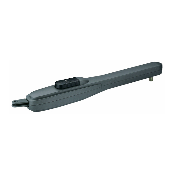
- Page 5 LAYOUT IMPIANTO ARATTERISTICHE TECNICHE PRINCE è un’operatore in grado di movimentare cancelli a battente con ante lunghe fino a 2 m e pesanti fino a 250 kg (Fig. 1). PRINCE è stato concepito per lavorare senza finecorsa elettrici, ma solo meccanici. NOTA BENE: Per mantenere una efficace posizione di chiusura é...
- Page 6 INSTALLAZIONE PRINCE Componenti da installare secondo la norma EN12453 ONTROLLO PRE-INSTALLAZIONE Le ante devono essere solidamente fissate ai cardini delle colonne, non TIPO DI COMANDO USO DELLA CHIUSURA devono flettere durante il movimento e devono muoversi senza attriti. Persone esperte Persone esperte Uso illimitato Prima d’installare PRINCE è...
- Page 7 Attacco colonna Misure da rispettare per una corretta installazione Min.÷Max Attacco anta 13,5 S2-X 13,5 S2-Y 13,5 S3-X S3-Y S3-X 90° S3-X 1÷2 19,5 S3-X 21,5 S1-Z S1-Z Qualora il pilastro fosse molto largo e non fosse possibile installare l’elettroriduttore rispettando la S1-Y 110°...
-
Page 8: Collegamenti Elettrici
ERMO MECCANICO - OPTIONAL (Cod. ACG8088) Fermo meccanico OPTIONAL per fermare la chiusura in caso il cancello sia privo di un fermo a terra. EGOLAZIONE FINECORSA MECCANICI Per posizionare i fermi si deve agire come da schema (Fig. 9). Per ottenere l’apertura desiderata è sufficiente spostare il fermo (A) e bloccarlo serrando la vite da 8mA con una chiave fissa n°13. - Page 9 Quadro elettronico K2 24V cod. ABK0024 K2 24V CRX cod. ABK0025...
- Page 10 SPEED ATTENZIONE Ricordarsi di regolare i sensori di impatto (vedi paragrafo C). SEC.TRANSF. Connettore per secondario trasformatore connettore per radio ricevitore RIB ad innesto con alimentazione a 24Vdc MOTOR 1 Collegamento MOTORE 1 (senza polarità) MOTOR 2 Collegamento MOTORE 2 (senza polarità)
- Page 11 L9 programmazione attivata (rosso) SETTAGGI L10 programmazione codici radio (verde) L11 comando apertura pedonale (verde) DIP 1 (ON) - CONTROLLO SENSO DI ROTAZIONE L12 contatto costa (NC) (rosso) DEL MOTORE (PUNTO C) DIP 2 (ON) - PROGRAMMAZIONE TEMPI (PUNTO D) RELE’...
- Page 12 5 - Raggiunto il fermo meccanico di apertura, il SENSORE DI fisso). CORRENTE ferma M2 (con memorizzazione del tempo) => Nello Per ripetere la programmazione posizionare i DIP1 e 2 su OFF, stesso momento si attiva il conteggio del tempo d›attesa prima della chiudere l’anta 1 e ripetere la procedura sopra descritta.
- Page 13 dell’ora impostata, si avra la chiusura immediata dell’automazione, apre. Durante il funzionamento le fotocellule altrimenti sarà necessario dare un comando. intervengono sia in apertura (con ripristino del moto in apertura dopo un tempo di mezzo PED. BUTT (COM-PED.BUTT) secondo), che in chiusura (con ripristino del Comando dedicato ad un’apertura parziale e alla sua richiusura.
-
Page 14: Caratteristiche Tecniche
comando. CARATTERISTICHE TECNICHE RADIO (modello K2 24V crx) - Frequenza Ricezione 433,92MHz SPIA DI SEGNALAZIONE CANCELLO APERTO (COM-SIGNAL) - Impedenza 52 OHM Ha il compito di segnalare gli stati di cancello aperto, parzialmente aperto - Sensibilità >2,24µV o comunque non chiuso totalmente. Solo a cancello completamente - Tempo eccitazione 300ms chiuso si spegne. - Page 15 OPTIONAL - Per i collegamenti ed i dati tecnici degli accessori attenersi ai relativi libretti di istruzione. CHEDA DI CARICA BATTERIA HIAVISTELLO MECCANICO Il tempo di ricarica completa delle batterie da 12Vdc 2,2Ah (n° 2 pezzi Chiavistello meccanico per cancelli a due ante. cod.
-
Page 16: Schéma Détaillé De L'installation
SCHÉMA DÉTAILLÉ DE L’INSTALLATION ARACTERISTIQUES TECHNIQUES PRINCE est un opérateur utilisé pour manoeuvrer des portails à battans jusqu’à 2 m de longeur et 250 kg de poids (Fig.1). Les opérateurs PRINCE utilisent les fin de course mécaniques intégrés, de ce fait évitant le devoir installer des fins de course électriques. - Page 17 INSTALLATION PRINCE Parties à installer conformément à la norme EN12453 ONTROLE PRE-INSTALLATION Le portail à battant doit être solidement fixé aux poteaux, ne doit pas flechir TYPE DE COMMANDE USAGE DE LA FERMETURE pendant le mouvement et doit pouvoir manoeuvrer sans effort. Personne expertes Personne expertes Usage illimité...
- Page 18 Attache poteau Mesures à respecter pour une correcte installation Min.÷Max Attache vantail 13,5 S2-X 13,5 S2-Y 13,5 S3-X S3-Y S3-X 90° S3-X 1÷2 19,5 S3-X 21,5 S1-Z S1-Z Si le pilier est très large et qu’il n’est pas possible d’installer le motoréducteur en respectant la mesure S1-Y 110°...
-
Page 19: Entretien
RRÊT MÉCANIQUE - OPTION (Cod. ACG8088) Arrêt mécanique en OPTION pour arrêter la fermeture si le portail n’est pas pourvu de dispositif d’arrêt au sol. EGLAGE FINS DE COURSE MECANIQUES Pour positionner les colliers, il est necessaire agir selon les indications du schema (Fig. -
Page 20: Coffret Electronique
Coffret electronique K2 24V cod. ABK0024 K2 24V CRX cod. ABK0025... - Page 21 ATTENTION Rappelez-vous d›ajuster les capteurs d›impact (voir le paragraphe C). SEC.TRANSF. Connecteur pour transformateur secondaire ou connecteur pour radio récepteur RIB à enclenchement avec alimentation à 24Vdc MOTOR 1 Connexion MOTEUR 1 (sans polarité) MOTOR 2 Connexion MOTEUR 2 (sans polarité) Alimentation 230Vac 56/60Hz - externe à...
- Page 22 L8 commande bouton K-Button (vert) SETTAGES L9 programmation activée (rouge) L10 programmation codes radio (vert) DIP 1 (O N) - CONTRôLE SENS DE ROTATION DU L11 Commande ouverture piétonne (vert) MOTEUR (POINT C) L12 Contact cordon (NO) (rouge) DIP 2 (ON) - PROGRAMMATION TEMPS (POINT D) DIP 1-2 MÉMORISATION/EFFACEMENT CODES RADIO POUR RELAIS COMMANDE MOTEUR (SEULEMENT MODÈLE CRX)
-
Page 23: Programmation Des Temps Pour 1 Moteur
4 - Une fois la butée mécanique d’ouverture atteinte, le DETECTEUR 4 - Attendre le temps que l’on veut qu’il reste ouvert (peut être exclu DE COURANT arrête M1 (avec mémorisation du temps) => Au avec le DIP3 sur OFF), appuyer ensuite sur le bouton piéton pour même moment M2 s’active et s’ouvre. - Page 24 MODALITE D’APPLICATION FONCTIONNEMENT APRES UNE COUPURE DE COURANT (SANS En connectant un interrupteur et/ou une horloge de type journalier/ BATTERIES) hebdomadaire (à la place ou en parallèle du bouton d’ouverture N.A. Au retour du courant, nous conseillons de faire ouvrir complètement “COM-K-BUTTON”), il est possible d’ouvrir et de maintenir ouverte le portail.
- Page 25 ALARME DE DETECTEUR DE COURANT Si après une première intervention du détecteur de courant en ouverture ou en fermeture, il y en a une seconde, évidemment dans le sens contraire, le portail s’arrête et intervertit alors le mouvement pendant 1 seconde. L’état d’alarme sera affiché...
-
Page 26: Verrou Mecanique
Pour les branchements et les données techniques des accessoires, se conformer aux livrets OPTIONS - d’instruction correspondants. ICHE DE CHARGE BATTERIE ERROU MECANIQUE Le temps de la recharge complète des batteries de 12Vdc 2,2Ah Pour le verrouillage au sol du premier vantail code ACG5000 (n°... -
Page 27: System Lay-Out
SYSTEM LAY-OUT ECHNICAL FEATURES PRINCE 24V is a linear operator designed for swing gates long up to 2 m and weight up to 250 kg (Pic. 1). PRINCE 24V works without electric limit switches, but with mechanical stoppers. N.B.: It is advisable to fit an electrical lock to ensure an efficient gate locking. - Page 28 INSTALLATION PRINCE Parts to install to comply EN 12453 standard COMMAND TYPE RE-INSTALLATION CHECK LIST The gate leaves must be firmly fixed to the hinges on the gate pillars, they COMMAND TYPE USE OF THE SHUTTER must not flex during the movement and they must swing without any friction. Skilled persons Skilled persons Unrestricted use...
- Page 29 In order to carry out a proper installation of the operator, it is necessary to comply with the geometry measurement shown in the tables below. Column attachment Respect the measures for a correct installation Min.÷Max Leaf attachment 13,5 S2-X 13,5 S2-Y 13,5 S3-X...
-
Page 30: Electric Connections
ECHANICAL STOPPER - OPTIONAL (Code ACG8088) Optional mechanical stopper to stop the closing, if the gate is not fitted with a floor stopper. ECHANICAL STOPPER ADJUSTMENT To adjust the stoppers you have to follow the scheme (Pic. 9). To set the opening limit it is enough to fix the stopper (A) in the needed position by tightening the 8mA screw with a n. - Page 31 Electric board K2 24V code ABK0024 K2 24V CRX code ABK0025...
-
Page 32: Control Panel Features
SENS SENS SPEED SEC.TRANSF. Connection to secondary coil of transformer RADIO for radio receiver RIB, 24 Vdc supply MOTOR 1 Connection MOTOR 1 (no polarity) Main power supply 230 Vac 50/60 Hz (120V/60Hz MOTOR 2 Connection MOTOR 2 (no polarity) - Page 33 POINT B - L1 photocell contact (NC) (red) SETTINGS L2 --- L3 --- DIP 1 MOTOR ROTATION DIRECTION CHECK (SEE L4 gate opening M1 (green) POINT C) L5 gate closing M1 (red) DIP 2 PROGRAMMING (SEE POINT D) L6 gate opening M2 (green) DIP 1-2 STORING/ERASING RADIO CODES FOR MOTOR L7 gate closing M2 (red) CONTROL (ONLY CRX CONTROL BOARD) (SEE POINT G, H...
- Page 34 POINT D - slowly. PROGRAMMING FOR 2 MOTORS (#) 4 - Press the pedestrian pushbutton PED. BUTT, motor M1 opens. DURING THE PROGRAMMING, THE CURRENT SENSOR IS 5 - When the motor M1 leaf is opened enough for the pedestrian crossing, ALWAYS ACTIVE.
- Page 35 DIP 6 - ON => The K BUTT, the PED BUTT button, the RADIO REMOTE ELECTRIC LOCK coupling FACILITY buttons perform the cyclic command open-stop-close- The DIP 10 in the ON position enables the Electric Lock coupling Facility. open-stop-etc. Once the gate has closed, a short hammering close pulse (0.5 seconds) DIP 6 - OFF =>...
-
Page 36: Technical Specifications
JP4 MUST BE LEFT OPEN. ECHNICAL SPECIFICATIONS FLASHING LIGHT (BLINKER - A+) - Power supply voltage 230V~ ±10% (120V/60Hz Connect the flashing light to outputs A+ and BLINKER, use flashing lights upon request) ACG7061 and 24V bulbs of 20W maximum. - Frequency 50/60 Hz NB: This electronic PK2-24V board can only supply power to FLASHING... -
Page 37: Accessories
For the connections and the technical data of the optional equipments follow the relevant ACCESSORIES - handbooks. ATTERY CHARGE CARD ECHANICAL BOLT The time needed to charge completely the 12Vdc 2,2Ah batteries (n° Mechanical bolt suitable for 2 leaves gate to latch closed the gate to the 2 batteries connected in series, optional cod. -
Page 38: Technische Eigenschaften
ANLAGEN LAY-OUT ECHNISCHE EIGENSCHAFTEN PRINCE ist eine Antriebe die für Drehtore mit den Torflügen bis zu 2 m und 250 kg verwendbar sind (Abb. 1). PRINCE benutzen eingebaute mechanische Stopper und so ist es nicht Notwendig einen elekrtrischen Endschalter zu installieren. - Page 39 INSTALLATION PRINCE Komponenten zur Installation nach der Norm EN1253 RÜFUNG VON DER MONTAGE STEUERUNGSSYSTEM ANWENDUNG DER SCHLIESSUNG Das Flugeltor muß fest an der Angelpunkten der Träger fixiert sein, darf sich während der Bewegung nicht biegen und ohne Reibung bewegen. Fachpersonen Fachpersonen Grenzlose (öffentlicher Platz)
- Page 40 Halterung Pfeiler Die korrekten Abmessungen und Installation mit einem Stopper im Antrieb Min.÷Max Halterung Torfluegel 13,5 S2-X 13,5 S2-Y 13,5 S3-X S3-Y S3-X 90° S3-X 1÷2 19,5 S3-X 21,5 S1-Z S1-Z Falls der Torantrieb nicht mit dem richtigen Maß (B) montiert werden kann, da der Torträger zu breit ist, S1-Y 110°...
- Page 41 ECHANISCHE SPERRVORRICHTUNG - OPTIONEN (Kode ACG8088) Als Zubehör eine mechanische Sperrvorrichtung, die das Gittertor beim Schließen anhält, falls keine Feststellvorrichtung auf dem Boden vorhanden ist. INSTELLUNG DES MECHANISCHEN ENDSCHALTERS Um die Endschalter einzustellen, müssen Sie wie in der Abbildung handeln (Abb.
-
Page 42: Elektronische Steuerung
Elektronische steuerung K2 24V code ABK0024 K2 24V CRX code ABK0025... - Page 43 AUFMERKSAMKEIT Erinnern Sie sich, die Auswirkung Sensoren zu justieren (sehen Sie Paragraphen C). SEC.TRANSF. Verbinder für Sekundär Transformator für Radioempfänger RIB Steckverbindung mit Speisung zu 24Vdc MOTOR 1 Anschluss zu MOTOR 1 (ohne Polarität) MOTOR 2 Anschluss zu MOTOR 2 (ohne Polarität)
- Page 44 L8 Befehls-Schalttaste K-Button (grün) ANORDNUNGS-PROGRAMMIERUNG L9 Programmierung aktiviert (rot) L10 Programmierung Radio-Kode (grün) DIP 1 (O N) - KONTROLLE DES ROTATIONSSINN DES L11 Befehl Öffnung für Fußgänger (grün) MOTORS (PUNKT C) L12 Rippen-Kontakt (NC) (rot) DIP 2 (ON) - ZEITEN PROGRAMMIERUNG (PUNTKT D) DIP 1-2 SPEICHERUNG/LÖSCHUNG DER RADIO-KODE FÜR RELE’...
- Page 45 2 - DIP 2 auf ON stellen=> Led L9 sendet kurze Blinklichter. dann DIP1 auf ON stellen (Led DL9 blinkt in langsamem Rhytmus). 3 - Schalttaste PROG. drücken => M1 öffnet. 2 - Schalttaste Fußgänger drücken (COM-PED.BUTT) => Torflügel 4 - Ist die mechanische Feststellvorrichtung der Öffnung erreicht, stoppt öffnet.
- Page 46 einer Toröffnung ausgeführt wird. In Gang gesetzt bei Wenn man bei geschlossenem Tor einen Öffnungsbefehl eingibt, wird geöffnetem Tor, wird sich dieses schließen, während das Tor für 0,5 Sekunden die Bewegung in Schließung ausführen (der/ einer Schließbewegung, wird sich das Tor wieder die Strom Sensor/en sind in dieser Fase außer Betrieb), gleichzeitig öffnen.
- Page 47 ÜBERWACHUNG RIPPEN FÜR DIE SICHERHEIT ECHNISCHE EIGENSCHAFTEN Durch den Eingang A+TEST und dem Jumper JP4 (geschlossen) besteht die Möglichkeit, die Rippe/en zu überwachen. - Feuchtigkeit < 95% ohne Kondensation Die Überwachung besteht in einem zweckmäßigem Rippe-Funktions- - Stromzufuhr 230V~ ±10% (120V/60Hz auf Test, der bei jeder kompletten erreichten Toröffnung erfolgt.
- Page 48 Für die Anschlüsse und die technischen Daten der Zubehöre verweisen wir auf die OPTIONEN - entsprechenden Betriebsanleitungen. ATTERIE LADEKARTE ECHANISCHER RIEGEL Fuer zwei Fluegel, zur Verrieglung am Boden. Kode ACG5000 Die nötige Zeit für die komplette Batterieladung von 12Vdc 2,2Ah (Nr. 2 Stücke in Serie angeschlossen, Optional Kode ACG9515), beträgt bei erster Installierung 24 Stunden, mit Stromladung zu 0,03A.
-
Page 49: Características Técnicas
DISPOSICIÒN DE LA INSTALACIÒN ARACTERÍSTICAS TÉCNICAS PRINCE es un operador capaz de desplazar cancelas con batientes de hojas largas hasta 2 m y pesadas hasta 250 kg (Fig. 1). PRINCE ha sido concebido para trabajar sin finales de carrera eléctricos, sino sólo mecánicos. N. - Page 50 INSTALACIÓN PRINCE Componentes a instalar según la norma EN12453 ONTROLES DE LA PRE-INSTALACIÓN TYPO DE MANDO USO DEL CIERRE La puerta de batiente debe fijarse sólidamente a las bisagras de las columnas y no debe balancearse durante el movimiento. Personas expertas Personas expertas Uso ilimitado Antes de proceder a la instalación de PRINCE, es prudente verificar todos (fuera de un área pública*)
- Page 51 Enganche columna Medidas a respetar para una instalación correcta Min.÷Max Enganche cancela 13,5 S2-X 13,5 S2-Y 13,5 S3-X S3-Y S3-X 90° S3-X 1÷2 19,5 S3-X 21,5 S1-Z S1-Z En el caso de que el pilar fuera demasiado ancho y no fuese posible instalar el electroreductor respetando la S1-Y 110°...
-
Page 52: Conexiones Eléctricas
EGURO MECÁNICO - OPTIONAL (cód. ACG8088) Seguro mecánico opcional para detener el cierre en el caso de que la cancela no esté provisto de una seguro de tierra. JUSTE DE LOS FINALES DE CORRIDA MECÁNICOS Para posicionar los seguros se debe actuar según el esquema (Fig. 9). Para obtener la abertura deseada es suficiente mover el seguro (A) y boquearlo serrando la vite da 8mA con la llave fija n°... - Page 53 Panel electronico K2 24V code ABK0024 K2 24V CRX code ABK0025...
- Page 54 Recuerde ajustar los sensores del impacto (véase el párrafo C). SEC.TRANSF. Conector para transformador secundario RADIO conector para radio receptor RIB con engranaje con alimentación de 24Vdc MOTOR 1 Conexión del MOTOR 1 (sin polaridad) MOTOR 2 Conexión del MOTOR 2 (sin polaridad) Alimentación 230 Vac 50/60 Hz - externa a la...
- Page 55 RELÉ CONFIGURACIÓN RL1 RELÉ CIERRA MOTOR 1 RL2 RELÉ ABRE MOTOR 1 DIP 1 (ON) - CONTROL SENTIDO DE ROTACIÓN DEL RL3 RELÉ CIERRA MOTOR 2 MOTOR (PUNTO C) RL4 RELÉ ABRE MOTOR 2 DIP 2 (ON) - PROGRAMACIÓN DE LOS TIEMPOS (PUNTO D) DIP 1-2 MEMORIZACIÓN/ELIMINACIÓN DE CÓDIGOS RADIO FUSIBLES PARA EL MANDO MOTOR (SÓLO MODELO CRX) (PUNTO E)
- Page 56 por 5 segundos => la cancelación de la memoria se indica con dos centelleos PROGRAMACIÓN DE LOS TIEMPOS PARA 1 MOTOR (M1) (#) del led verde L10. A continuación el led L9 de programación permanece activo y es posible insertar nuevos códigos como en el procedimiento anteriormente ATENCIÓN: PARA ADMINISTRAR UN SÓLO MOTOR, REMOVER EL PUENTE descrito.
- Page 57 Con cancela cerrada, si se presiona un mando de abertura, la cancela por 0,5s DIP 5 - OFF => el motor y el intermitente parten contemporáneamente. DIP 5 - ON => el intermitente parte 3 segundos antes que el motor. ejecuta una moniobra de cierre (el/los sensores de corriente en esta fase no están habilitado/s) y contemporáneamente se activa la cerradura eléctrica (seguida de 0,5s de pausa y luego de la abertura de la cancela).
- Page 58 OPCIONALES - Para las conexiones y datos técnicos de los accesorios, consultar los manuales respectivos. ARJETA DE CARGA BATERÍA ESTILLO MECANICO El tiempo de carga completa de las baterías de 12Vdc 2,2Ah (n° 2 Pestillo mecanico para cancelas de 2 hojas. cód.
- Page 59 R.I.B. S.r.l. AZIENDA CON SISTEMA DI QUALITà CERTIFICATO 25014 Castenedolo - Brescia - Italy DA DNV Via Matteotti, 162 Tel. ++39.030.2135811 COMPANY WITH QUALITY Fax ++39.030.21358279 - 21358278 SYSTEM CERTIFIED www.ribind.it - ribind@ribind.it BY DNV DICHIARAZIONE DI CONFORMITÁ - DECLARATION OF COMPLIANCE DÉCLARATION DE CONFORMITÉ...
- Page 60 KIT PRINCE 24V CCA1263 BA01046 CME5235 CAL1158 CRS6204R CCA1327 CPL1163 DRL10X30I CME2125 CPL1164 CTC1269 DTE10X20I CTC1116 BA01076 CME9056 CVA1176 CTC1253 CPL1165 DAC4X14 CMO1286 DTM10X40I CME6085 CPL1127 DRD4 DTB55X40 DRL10X20I DDD10MAI ACG8088 CAL1157 CPL1167 DAC29X95 CEL1463 Questo prodotto è stato completamente progettato e costruito in Italia · Ce produit a été complètement développé et fabriqué en Italie · This product has been completely developed and built in Italy ·...