Table des Matières
Publicité
Les langues disponibles
Les langues disponibles
Liens rapides
0711
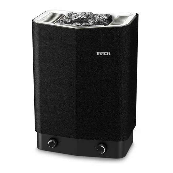
MEGA LINE
sauna
TYLÖ AB, Svarvaregatan 6, S-30250 Halmstad, Sweden.
Tel + 46-35 10 00 80, Fax + 46-35 102580. E-mail: info@tylo.se, Internet: www.tylo.se
Installations- och bruksanvisning.................................................... Svenska sid 2.
Vi tackar för Ert förtroende för Tylöprodukter. Tylö-bastuaggregat är kända som högklassiga och
långlivade produkter. Inkoppling skall utföras av behörig el-installatör. SPARA ANVISNINGEN! Efter
installation överlämnas denna till bastuns ägare eller till den ansvarige för bastun.
Innan några som helst åtgärder vidtas, läs bruksanvisningen och speciellt noga punkten "VARNINGAR" på sidan 2.
Installation and operating instructions.......................................... English page 5.
We thank you for your selection for our products. Tylö sauna heaters are noted for their high quality and
reliability. Wiring work should be carried out by a qualified electrician. SAVE THESE INSTRUCTIONS!
After installation, they should be given to the owner or operator of the sauna.
Prior to any measures, read these instructions carefully, especially the section "WARNINGS" on page 5 and
comply with them as well.
Installations- und Gebrauchsanleitung......................................... Deutsch Seite 8.
Wir danken Ihnen für das Vertrauen, das Sie Tylö-Produkten entgegenbringen. Tylö Saunaöfen sind
bekannt als hochwertige und langlebige Produkte. Der Anschluß ist von einem Elektriker auszuführen.
ANLEITUNG AUFBEWAHREN und nach erfolgter Installation dem Besitzer der Sauna oder der dafür
zuständigen Person auszuhändigen.
Bevor Sie irgend etwas unternehmen, lesen Sie bitte die Bedienungsanleitung – insbesondere den
Abschnitt „WARNUNGEN" auf S. 8 – sorgfältig durch.
Instructions d'installation et d'utilisation.................................. Français, page 11.
Nous vous remercions pour la confiance que vous manifestez concernant les produits Tylö. Les poêles
de sauna Tylö sont réputés pour être des produits de grande qualité et offrant une grande longévité. Le
branchement doit être effectué par un installateur électricien agréé. CONSERVER LES PRÉSENTES
INSTRUCTIONS ! Après l'installation, le manuel doit être remis au propriétaire du sauna ou à la
personne qui en est responsable.
Avant d'entreprendre la moindre intervention, bien lire les instructions d'utilisation et tout particulièrement
le point « MISES EN GARDE » de la page 2.
Art nr 29002555
1
Publicité
Table des Matières

Manuels Connexes pour Tylo MEGA LINE SO 6


Sommaire des Matières pour Tylo MEGA LINE SO 6
- Page 1 TYLÖ AB, Svarvaregatan 6, S-30250 Halmstad, Sweden. Tel + 46-35 10 00 80, Fax + 46-35 102580. E-mail: info@tylo.se, Internet: www.tylo.se Installations- och bruksanvisning......…..... Svenska sid 2. Vi tackar för Ert förtroende för Tylöprodukter. Tylö-bastuaggregat är kända som högklassiga och långlivade produkter.
- Page 2 På golv (EP, EH och EZ) VARNING! Aggregatet monteras på golvet och fästs med hjälp av fästplåten i • Övertäckning av bastuaggregat medför brandfara. bakbenet med två skruvar om golvet är av trä och med proppar om golvet • Användning utan välfyllt stenmagasin medför brandfara. är av sten.
- Page 3 Tabell 4, Kombinationstabell Belysning. bastuaggregat - separat manöverpanel Anslut belysningen enligt kopplingschema. Modell Passande manöverpaneler Fjärrmanövrering. 230-240V 3~ 230-240V~ 400-415V 3~ 200-208V~ 200-208V 3~ SO 6 TS 30, *TS 30, TS 16, TS 30, *TS 30, TS 30, Manöverpanelerna typ CC är redan förberedda för fjärrmanövrering från SO8, CC 10 / RB 30, CC 10 / RB 30,...
-
Page 4: Allmän Information
Temperaturskydd. fax:(46) 035 - 10 25 80 Aggregaten har inbyggt temperaturskydd i kopplingsdosan nedtill på e-post : info@tylo.se aggregatet. Temperaturskyddet utlöses automatiskt om risk för överhettning uppstår. Har skyddet utlöst är det oftast beroende på felaktig ventilation, felaktig placering av aggregatet eller felaktigt fyllt stenmagasin. - Page 5 At the floor (EP, EH, EZ) WARNING! The heater is placed on the floor and fastened with the fastening plate of • Do not cover the sauna heater. This creates a fire hazard. the back foot with two screws to a wooden floor or with wedge anchors to •...
- Page 6 Sauna heater – separate control panel combinations Lighting. Connect the lighting according to the wiring diagram. Heater Suitable control panel model 230-240V 3~ 230-240V~ 400-415V 3~ 200-208V~ 200-208V 3~ Remote control operation. SO 6 TS 30, *TS 30, TS 16, TS 30, *TS 30, TS 30, CC control panels are already prepared for remote-control operation from...
-
Page 7: General Information
Fig. 15. Recommendations for sauna construction: OPERATING INSTRUCTIONS A. Floor frame, corner posts, studs, ceiling frame. B. Battens, rafters, vents. HL, SO, WM and TS C. 50 mm mineral wool as heat insulation, approx. 20 mm air gap between insulation and outer wall. Temperature setting. - Page 8 Niemals Kabel mit PVC-Isolierung verwenden. Den Schaltplan finden Sie in WARNUNG! diesen Anleitungen (Abb. 16-23) sowie auf der Anschlußdose im Ofen. • Abdecken des Saunaofens bringt Feuergefahr mit sich. Die Installation ist vorzunehmen, bevor der Ofen an seinen • Bestimmungsplatz gebracht wird. Der Saunaofen darf niemals ohne Steine verwendet werden.
- Page 9 Tabelle 4, Fernbedienung Die Kontrollgeräte vom Typ CC sind bereits für Fernbedienung von einer oder Kombinationstabelle Saunaofen - separates Kontrollgerät mehreren Stellen aus vorbereitet. Saunaofen Passendes Kontrollgeräte Option: Externer Ein/Ausschalter (verzögerungsfrei Modell 230-240V 3~ 230-240V~ 400-415V 3~ 200-208V~ 200-208V 3~ Kann in einem beliebigen Abstand zur Sauna angebracht werden.
-
Page 10: Allgemeine Information
Bei Bedarf durch neue Dolerit-Steine ersetzen. TYLÖ AB, Svarvaregatan 6, S-30250 Halmstad, Schweden. Temperaturschutz Tel 035-10 00 80, Fax 035-102580. E-mail: info@tylo.se, Internet: www.tylo.se Tylö Saunaöfen sind mit integriertem Temperaturschutz ausgestattet, der in © Nachdruck, ganz oder teilweise, ohne schriftliche Genehmigung von Tylö verboten. Tylö... -
Page 11: Emplacement De Montage
bois fournies. Un mince lambris de bois n’est pas suffisamment solide et ATTENTION ! il faut installer par exemple une planche ou une plaque supplémentaire • en renfort autour des points d’ancrage derrière le panneau. Dans un mur Avant chaque séance de sauna, vérifier qu’il n’y a pas d’objets inadéquats dans la cabine de sauna ou sur le poêle de sauna. - Page 12 Tableau 2. Section des conducteurs et intensité. Tableaux de commande de type CC. Mode d’emploi : fourni avec le tableau de commande. 230- 230- 400- 400- 200- 200- Montage à une distance illimitée de la cabine de sauna. 240V 3~ 240V~ 415V 3~ 415V 2N~...
-
Page 13: Informations Générales
alors) ! Il est donc très important d’appliquer soigneusement nos porte ou de fenêtre et du silicone pour salles d’eau dans le joint entre indications concernant la ventilation du sauna. vitre et baguette. On empêche ainsi l’éventuelle eau de condensation qui recouvre la vitre de s’infiltrer dans le joint. -
Page 14: Déroulement D'une Séance De Sauna
Enclenchement immédiat : Tourner pour passer le premier 3, puis revenir au temps de fonctionnement voulu (1, 2 ou 3 heures). Le temporisateur s’arrête automatiquement en position 0. Enclenchement automatique : Tourner jusqu’au repère 9 puis revenir sur le temps de présélection voulu (= le temps jusqu’à ce que le poêle s’enclenche automatiquement). - Page 15 EP100/EH150 (min mm) (min mm) (min mm) HL, HL-S, SO 20mm " %& (min mm) (min mm) (min mm) max 400mm min 20mm (min mm) (min mm) (min mm) max 400mm min 20mm EP100, EH1 0 : A=80, B=80 EZ22 : A=100, B=1 0...
- Page 16 1500 1500 mm 1500 mm 8" 8" Sauna...
- Page 17 400 - 415 - 440 V 3~ = EP 00 =SO 6/8, WM 0 = EP 00 = EP 00 2 = TS 30-03, TS 30-0 2 2 = TS 6-3 B 2 = TS 6-3 A B C D A B C D Max 500 W 2.5 mm²...
- Page 18 400 - 415 - 440 V 2N~ 200 - 208 - 230 - 240 V 3~ = EP 00 = SO 6-8, WM 0 = EH 50, EZ225 Z X Y U V W Z X Y 2 = TS 30-03, TS 30-0 2 L L L U V W 2 = TS 58...