
Manuels Connexes pour Star TSP400


Sommaire des Matières pour Star TSP400
- Page 1 THERMAL PRINTER TSP400 INSTALLATION MANUAL GUIDE D’INSTALLATION AUFSTELLANLEITUNG MANUALE DI INSTALLAZIONE...
-
Page 3: Table Des Matières
TABLE OF CONTENTS 1. UNPACKING AND INSPECTION ............1 1-1. Unpacking ..................1 1-2. Handling Notes ................1 2. PARTS IDENTIFICATION AND NOMENCLATURE ...... 2 3. FERRITE CORE INSTALLATION *EUROPE ONLY ........Installation of the interface cable ferrite core ........4 Installation of the peripheral unit cable ferrite core ...... -
Page 4: Unpacking And Inspection
1. UNPACKING AND INSPECTION 1-1. Unpacking Check each item in the box against Figure 1-1 to make sure that you have everything (there should be five items). If any of these items are missing, contact your supplier. Sample paper roll Paper-roll shaft Ø24mm Ø28mm... -
Page 5: Parts Identification And Nomenclature
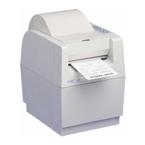
2. PARTS IDENTIFICATION AND NOMENCLATURE To get acquainted with the printer’s components and capabilities, refer to Figure 2-1. Printer cover Control panel Automatic paper cutter Protects the print head and Indicates printer status other internal components of (Controlled by command) and makes control of your printer. -
Page 6: Ferrite Core Installation *Europe Only
3. FERRITE CORE INSTALLATION *EUROPE ONLY NOTE: Take special care when following the procedures listed below. Two ferrite core noise filters, large and small, come packed with the printer. The small noise filter is for the RS232C serial interface cable, while the larger one is for the cable of peripheral units. -
Page 7: Installation Of The Interface Cable Ferrite Core
Installation of the interface cable ferrite core Clamp the small ferrite core onto the interface cable as shown in Fig. 3-2. Take care to avoid damaging the interface cable when installing the ferrite core. The ferrite core should be anchored firmly in place with the fastener that comes with it, as shown in Fig.3-3 and 3-4. -
Page 8: Connecting The Interface Cable
4. CONNECTING THE INTERFACE CABLE 4-1. RS-232C or RS-422A Serial interface Follow the procedures below to connect the interface cable: 1 Switch off the power to the printer and computer. 2 Insert the interface cable into the connector. (Be sure that the cable is Interface cable oriented correctly before inserting it.) - Page 9 TABLE DES MATIERES 1. DEBALLAGE ET INSPECTION ............7 1-1. Déballage ..................7 1-2. Remarques sur la manipulation ............ 7 2. IDENTIFICATION DES PIECES ET NOMENCLATURE ....8 3. INSTALLATION DU TORE DE FERRITE *EUROPE UNIQUEMENT ..Installation du tore de ferrite de câble d’interface ......10 Installation du tore de ferrite de câble de périphérique .....
-
Page 10: Deballage Et Inspection
1. DEBALLAGE ET INSPECTION 1-1. Déballage Vérifier chaque pièce de la boîte en se référant à la Figure 1 afin de s’assurer qu’on a bien tout reçu (il doit y avoir cinq pièces). En cas d’absence d’une de ces pièces, contacter le fournisseur. Rouleau de papier échantillon Arbre du rouleau de papier... -
Page 11: Identification Des Pieces Et Nomenclature
2. IDENTIFICATION DES PIECES ET NOMENCLATURE Se référer à la Figure 2-1 pour se familiariser avec les composants et capacités de l’imprimante. Couteau de papier Couvercle d’imprimante Tableau de commande Automatic paper cutter automatique Protège la tête d’impression ainsi Indique l’état de l’imprimante et (pilotage par commande) que d’autres composants internes (Controlled by command) -
Page 12: Installation Du Tore De Ferrite
3. INSTALLATION DU TORE DE FERRITE *EUROPE UNIQUEMENT REMARQUE: Prendre des précautions spéciales en suivant les procédures indiquées ci-dessous: Deux filtres antibruit à tore de ferrite, un grand et un petit sont emballés avec l’imprimante. Le petit filtre antibruit est prévu pour le câble d’interface série RS232C et le grand doit être utilisé... -
Page 13: Installation Du Tore De Ferrite De Câble D'interface
Installation du tore de ferrite de câble d’interface Serrer le petit tore de ferrite au câble d’interface de la manière indiquée à la Fig. 3-2. Prendre les précautions d’usage pour éviter d’endommager le câble d’interface lors de l’installation du tore de ferrite. Il faut bien immobiliser le tore de ferrite au moyen de l’attache fournie, comme indiqué... -
Page 14: Raccordement Du Câble D'interface
4. Raccordement du câble d’interface 4-1. Interface série RS-232C ou RS-422A Suivre les procédures indiquées ci-dessous pour relier le câble d’interface 1 Couper l’alimentation à l’impri- mante et à l’ordinateur. 2 Insérer le câble d’interface dans le Câble d’interface connecteur. (S’assurer que le câble Interface cable est orienté... - Page 15 INHALTSVERZEICHNIS 1. AUSPACKEN UND KONTROLLE ..........13 1-1. Auspacken .................. 13 1-2. Hinweise ..................13 2. FUNKTION UND BEZEICHNUNG DER EINZELNEN BAUTEILE .. 14 3. INSTALLATION DER FERRITKERNE *NUR EUROPA ..... Installation des Ferritkerns für das Schnittstellenkabel ..... 16 Installation des Ferritkerns für das Peripheriegerätekabel ....16 4.
-
Page 16: Auspacken Und Kontrolle
1. AUSPACKEN UND KONTROLLE 1-1. Auspacken Überprüfen Sie an Hand von Abbildung 1 die Teile in der Verpackung, und stellen Sie sicher, daß alle nötigen Positionen geliefert wurden; es sollten fünf sein. Falls eines der Teile fehlen sollte, wenden Sie sich bitte an Ihren Händler. Papierrolle Achse für die Papierrolle... -
Page 17: Funktion Und Bezeichnung Der Einzelnen Bauteile
2. FUNKTION UND BEZEICHNUNG DER EINZELNEN BAUTEILE Machen Sie sich in Abbildung 2-1 mit den Bestandteilen des Druckers und seinen Funktionen vertraut. Automatischer Druckerklappe Bedienfeld Automatic paper cutter Papierschneider Sie schützt den Druckkopf und Es zeigt den Druckerstatus an, und (befehlsgesteuert) andere Bauteile im Inneres Ihres (Controlled by command) -
Page 18: Installation Der Ferritkerne
3. INSTALLATION DER FERRITKERNE *NUR EUROPA HINWEIS: Beachten Sie die folgenden Schritte besonders sorgfältig. Zwei Ferritkerne zum Filtern von Störungen – ein großer und ein kleiner – werden mit dem Drucker geliefert. Der kleine Entstörungsfilter findet am Kabel für die serielle RS232C-Schnittstelle Verwendung, das große am Kabel für Peripheriegeräte. -
Page 19: Installation Des Ferritkerns Für Das Schnittstellenkabel
Installation des Ferritkerns für das Schnittstellenkabel Klemmen Sie den kleinen Ferritkern auf das Schnittstellenkabel, siehe Abbil- dung 3-2. Achten Sie darauf, daß bei der Installation des Ferritkerns das Kabel nicht beschädigt wird. Der Ferritkern sollte mit dem mitgelieferten Kabelbinder sicher an seinem Platz befestigt werden. Siehe Abbildungen 3-3 und 3-4. Installation des Ferritkerns für das Peripheriegerätekabel Klemmen Sie den großen Ferritkern auf das Kabel für die Peripheriegeräte. -
Page 20: Anschluss Des Schnittstellenkabels
4. ANSCHLUSS DES SCHNITTSTELLENKABELS 4-1. Serielle Schnittstellen RS-232C oder RS-422A Gehen Sie zum Anschluß des Schnittstellenkabels vor wie unten beschrieben. 1 Schalten Sie Drucker und Compu- ter aus. 2 Stecken Sie das Schnittstellenkabel Schnittstellenkabel in die Buchse. (Vergewissern Sie Interface cable sich, daß... - Page 21 INDICE 1. APERTURA E CONTROLLO DELLA CONFEZIONE ....19 1-1. Apertura della confezione ............19 1-2. Avvertenze ................. 19 2. IDENTIFICAZIONE E NOMENCLATURA DELLE PARTI ..20 3. INSTALLAZIONE DEGLI ANELLI DI FERRITE *SOLO EUROPA .. Installazione dell’anello di ferrite del cavo d’interfaccia ....22 Installazione dell’anello di ferrite del cavo dell’unità...
-
Page 22: Apertura E Controllo Della Confezione
1. APERTURA E CONTROLLO DELLA CONFEZIONE 1-1. Apertura della confezione Confrontare il contenuto della confezione con i componenti mostrati nella Figura 1-1 per controllare di aver ricevuto tutto (nella scatola dovrebbero esserci cinque componenti). Nel caso mancasse qualcuna di queste parti, contattare il fornitore presso cui si è... -
Page 23: Identificazione E Nomenclatura Delle Parti
2. IDENTIFICAZIONE E NOMENCLATURA DELLE PARTI Esaminare la Figura 2-1 per conoscere i componenti e le funzionalità della stampante. Taglierina della carta Coperchio della stampante Pannello di controllo Automatic paper cutter automatica Protegge la testina di stampa e Indica lo stato della stampante e (Controllata tramite comando) gli altri componenti interni della (Controlled by command) -
Page 24: Installazione Degli Anelli Di Ferrite
3. INSTALLAZIONE DEGLI ANELLI DI FERRITE *SOLO EUROPA NOTA: Prestare particolare attenzione durante l’esecuzione delle procedure indicate di seguito. Insieme alla stampante vengono forniti in dotazione due anelli di ferrite, uno grande e uno piccolo, da utilizzare come filtri per la soppressione di eventuali disturbi. -
Page 25: Installazione Dell'anello Di Ferrite Del Cavo D'interfaccia
Installazione dell’anello di ferrite del cavo d’interfaccia Fissare l’anello di ferrite piccolo sul cavo d’interfaccia come mostrato in Fig. 3-2, facendo attenzione a non danneggiare il cavo d’interfaccia. L’anello di ferrite va saldamente bloccato in posizione con la fascetta di fissaggio fornita in dotazione, come mostrato nelle Fig. -
Page 26: Collegamento Del Cavo D'interfaccia
4. COLLEGAMENTO DEL CAVO D’INTERFACCIA 4-1. Interfaccia seriale RS-232C o RS-422A Per collegare il cavo d’interfaccia, eseguire le procedure indicate di seguito: 1 Spegnere sia la stampante che il computer. 2 Inserire il cavo d’interfaccia nel Cavo d’interfaccia connettore (assicurarsi che il cavo Interface cable sia orientato nel senso corretto pri- ma di inserirlo). - Page 27 APPENDIX DIP SWITCHES DIP switches are located on the interface board. The number of switches varies according to the board, as follows. Centronics No DIP switches RS-232C One 8-bit DIP switch RS-422A One 8-bit DIP switch and one 4-bit DIP switch –...
-
Page 28: Dip-Switch Settings
DIP-switch settings a) DIP switch #1 (RS-232C, RS-422A) Switch Setting Baud Baud Handshaking X-ON/X-OFF Data bits 8 bits 7 bits Parity type Not used Used Parity type Even DCI/DC3 Invalid Valid (RS-232C only) When turning power ON * Refer to the table below. Baud 2400BPS 4800BPS... -
Page 29: Print Density Adjustment
Print Density Adjustment Since the sensitivity of different types of heat-sensitive paper varies, you can adjust the print density by varying the current supplied to the thermal head. Variable resistor used to adjust the print density The print density can be adjusted using the variable resistor inside the hole beside the interface connector on the back of the printer. -
Page 30: Sensor Adjustment
Sensor Adjustment Sensor levels are adjusted at the factory. If necessary, you can readjust the levels as described below. 1) Remove the ROM cover located beneath the paper-roll holding area. 2) Hold down the FEED and ON LINE switches while switching on the power, and continue to hold them down until you hear a triple beep. - Page 31 EPROM Main PCB Interface PCB Variable Resistances (Sensor Adjustment Knobs) – 28 –...
- Page 32 Connectors and Signal Names (Serial Interface) RS-232C Interface Pin no Signal name Direction Function F-GND – Frame ground Outgoing data Incoming data Request To Send: The printer sets this signal to “SPACE” when it is ready to send. The host sets this signal to “SPACE” when it is ready to send.
-
Page 33: Interface Connections
RS-422A Interface Pin no Signal name Direction Function SD(+) These pins carry data from the printer. SD(–) RD(+) These pins carry data to the printer. RD(–) The host sets this signal to “SPACE” when it CS(+) is ready to send. NOTE: The printer does not monitor this signal. - Page 34 [RS-422A] Printer side Host side Twisted pair cable Printer #n Printer #n+1 – 31 –...
- Page 35 Connectors and Signal Names (Parallel Interface) (18) Conforms to Amphenol connector 57-30360 (36) (19) (Printer Side) Signal Name Sample Circuit Ω 4.7k DATA 1 74LS-equivalent DATA 8 1kΩ 74LS-equivalent STROBE 100Ω 1000pF 1.8kΩ BUSY 74LS-equivalent – 32 –...
- Page 36 Pin no Signal name Direction Function Strobe pulse for data read. Usually HIGH; STROBE goes LOW to trigger data read. Parallel data lines for eight-bit data. HIGH DATA 1~8 is “1”; LOW is “0”. Printer outputs this pulse for approxi- mately 9µs to indicate that data read is completed.
- Page 37 Peripheral Unit Drive Circuit A drive circuit for driving peripheral units (such as cash drawers) is featured on the main logic board of this printer. A modular connector for driving peripheral units is featured on the output side on the drive circuit. When using this circuit, connect the cable for the peripheral unit.
- Page 38 Drive circuit The recommended drive circuit is shown. [Drive output 24V, max. 1.0 A] With shield Peripheral unit 1 +24V 7824 M-GND 4.7kΩ 1/4W M-GND Peripheral unit 2 Compulsion switch Frame ground NOTES: 1. Peripheral units #1 and #2 cannot be driven simultaneously. When driving a device continuously, do not use drive duty above 20%.
- Page 39 Tel: (908) 572-9512, Telefax: (908) 572-5095, Telex: 299766 STAR UR STAR MICRONICS DEUTSCHLAND GMBH Westerbachstraße 59, D-60489 Frankfurt/Main 90, Germany Tel: 0697-89990, Telefax: 0697-81006, Telex: 417 5825 STAR D HEAD OFFICE STAR MICRONICS U.K. LTD. STAR MICRONICS CO., LTD. Star House, Peregrine Business Park, Gomm Road,...