Table des Matières
Publicité
Les langues disponibles
Les langues disponibles
Liens rapides
Publicité
Chapitres
Table des Matières

Manuels Connexes pour JUMO variTRON 300


Sommaire des Matières pour JUMO variTRON 300
- Page 1 JUMO variTRON 300 Zentraleinheit 705003 Central Processing Unit 705003 Unité centrale 705003 Montageanleitung Installation Instructions Notice de montage 70500300T94Z000K000 V3.00/DE-EN-FR/00731924/2021-11-25...
- Page 3 JUMO variTRON 300 Automatisierungssystem Zentraleinheit 705003 Montageanleitung 70500300T94Z000K000 DE/00731924...
- Page 4 Weitere Informationen und Downloads qr-705003-de.jumo.info...
-
Page 5: Table Des Matières
Inhalt Inhalt Einleitung ........... 5 Sicherheitshinweise . - Page 6 Inhalt 4.1.4 Gehäuse und Umgebungsbedingungen ........28 4.1.5 Zulassungen und Prüfzeichen .
-
Page 7: Einleitung
Einleitung 1 Einleitung Sicherheitshinweise Allgemein Diese Anleitung enthält Hinweise, die Sie zu Ihrer eigenen Sicherheit sowie zur Vermeidung von Sach- schäden beachten müssen. Diese Hinweise sind durch Zeichen unterstützt und werden in dieser Anlei- tung wie gezeigt verwendet. Lesen Sie diese Anleitung, bevor Sie das Gerät in Betrieb nehmen. Bewahren Sie die Anleitung an ei- nem für alle Benutzer jederzeit zugänglichen Platz auf. -
Page 8: Entsorgung
1 Einleitung ENTSORGUNG! Dieses Gerät und, falls vorhanden, Batterien gehören nach Beendigung der Nutzung nicht in die Müll- tonne! Bitte lassen Sie sie ordnungsgemäß und umweltschonend entsorgen. Bestimmungsgemäße Verwendung Das Gerät ist für die Verwendung in industrieller Umgebung bestimmt, wie in den technischen Daten spezifiziert. -
Page 9: Warenannahme, Lagerung Und Transport
Beschreibung des aufgetretenen Fehlers Das Reparatur-Begleitschreiben (Begleitschreiben für Produktrücksendungen) kann im Internet von der Homepage des Herstellers heruntergeladen werden: http://produktruecksendung.jumo.info Schutz gegen Elektrostatische Entladung (ESD) (ESD = Electro Static Discharge) Zur Vermeidung von ESD-Schäden müssen elektronische Baugruppen oder Bauteile in ESD-geschütz- ter Umgebung gehandhabt, verpackt und gelagert werden. -
Page 10: Entsorgung
1 Einleitung 1.4.4 Entsorgung Entsorgung des Verpackungsmaterials Das gesamte Verpackungsmaterial (Kartonagen, Einlegezettel, Kunststofffolien und -beutel) ist voll recyclefähig. Die landesspezifischen Gesetze und Vorschriften zur Abfallbehandlung und Entsorgung sind zu beach- ten. Entsorgung des Gerätes ENTSORGUNG! Das Gerät oder ersetzte Teile (auch Batterien) gehören nach Beendigung der Nutzung nicht in die Müll- tonne, sondern sind ordnungsgemäß... -
Page 11: Geräteausführung Identifizieren
1 Einleitung Geräteausführung identifizieren 1.5.1 Typenschild Lage Das Typenschild (A) ist auf dem Modulgehäuse aufgeklebt. Inhalt Das Typenschild beinhaltet wichtige Informationen. Unter anderem sind dies: Beschreibung Bezeichnung auf dem Beispiel Typenschild Gerätetyp 705003/01008-00-36/000,224 Teile-Nr. 00123456 Fabrikations-Nummer F-Nr. 0070033801220500006 Spannungsversorgung DC 24 V, +25/-20 % Gerätetyp (Typ) Die Angaben auf dem Typenschild mit der Bestellung vergleichen. -
Page 12: Bestellangaben
Gerät steht Zentraleinheit JUMO variTRON 500 (Typ 705002) zur Verfügung. Ihr Ansprechpartner im Technischen Vertrieb be- rät Sie gerne, um für Ihre Anwendung die geeignete Zentraleinheit auszuwählen. Nur in Verbindung mit Typenzusatz 224. Nicht verfügbar in Systemversion 6. (2) (3) (4) (5) -
Page 13: Lieferumfang
1 Einleitung Weitere Typenzusätze nacheinander aufführen und durch Komma trennen. 1.5.3 Lieferumfang 1 Zentraleinheit Typ 705003 in der bestellten Ausführung 1 Lambda/4-Antenne (nur bei Gerät mit Wireless-Schnittstelle) 1 Montageanleitung 1.5.4 Zubehör Bezeichnung Teile-Nr. RJ45-Patchkabel SF/UTP, Länge 0,3 m 00747472 Antennenleitung, Länge 1 m, Impedanz 50 Ohm mit vorkonfektioniertem Schraubver- 00710813 binder, T 85 °C... -
Page 14: Verfügbare Technische Dokumentation
Die Dokumentation für das Automatisierungssystem wendet sich an Anlagenhersteller und Anwender mit fachbezogener Ausbildung und besteht aus den folgenden Dokumenten (bisherige Dokumenten- nummer in Klammern). 1.6.1 Zentraleinheit Produkt Dokument gedruckt PDF-Datei variTRON 300 Typenblatt 70500300T10... Betriebsanleitung 70500300T90... Zentraleinheit Montageanleitung 70500300T94... 1.6.2... -
Page 15: Sondermodule
Montageanleitung 70504200T94... (ab Systemversion Routermodul Typenblatt 70504300T10... 1-Port Montageanleitung 70504300T94... (ab Systemversion 1.6.4 Panels Produkt Dokument gedruckt PDF-Datei JUMO variTRON Typenblatt 70507000T10... Webpanels 1.6.5 Netzteile Produkt Dokument gedruckt PDF-Datei Netzteile 24 V Typenblatt 70509000T10... Bedienungsanleitung QS3.241 Bedienungsanleitung QS5.241 Bedienungsanleitung QS10.241... - Page 16 1 Einleitung...
-
Page 17: Montage
Montage 2 Montage Allgemeines zur Montage/Demontage GEFAHR! Beim Mehrkanal-Reglermodul 705010 und beim Relaismodul 705015 können die Lastkreise von Relais- oder Halbleiterrelais-Ausgängen mit einer gefährlichen elektrischen Spannung (z. B. 230 V) betrieben werden. Es besteht die Gefahr eines Stromschlags. Vor der Montage/Demontage dieser Module oder vor dem Herausnehmen des Moduleinschubs sind die Lastkreise spannungsfrei zu schalten und die Klemmleisten vom Modul abzuziehen. -
Page 18: Montage/Demontage Auf Hutschiene
2 Montage Mindestabstände HINWEIS! Der obere Mindestabstand 35 mm ist ausreichend, um ein Kabel an der Antennenbuchse anzuschlie- ßen. Wenn die Antenne direkt an der Antennenbuchse angeschlossen wird, ist ein Mindestabstand von 100 mm erforderlich. Montage/Demontage auf Hutschiene Alle Module Systems sind für... - Page 19 2 Montage Montage der Zentraleinheit 705003 (A1) (A2) Vorgehensweise: 1. Zentraleinheit (A) von oben in die Hutschiene einhängen (A1). 2. Zentraleinheit nach unten schwenken, bis sie einrastet (A2). HINWEIS! Gegebenenfalls die Abschlusswiderstände der RS485-Schnittstelle vor der Montage aktivieren (siehe Kapitel „Elektrischer Anschluss“)!
- Page 20 2 Montage Demontage der Zentraleinheit 705003 (A4) (B1) (A2) (C3) Vorgehensweise: 1. Gegebenenfalls Anschlusskabel (Schnittstellen) entfernen. 2. Gegebenenfalls verdrahtete Anschlussklemme (B) der Zentraleinheit (A) mit einem Schraubendre- her lösen und nach vorn abziehen (B1). 3. Passenden Schraubendreher (C) in den Entriegelungsschlitz der Zentraleinheit stecken (A2) und nach oben drücken (C3).
-
Page 21: Abmessungen
2 Montage Abmessungen 17.5 94.5 101.5... - Page 22 2 Montage...
-
Page 23: Elektrischer Anschluss
Elektrischer Anschluss 3 Elektrischer Anschluss Installationshinweise HINWEIS! Diese Installationshinweise gelten für das gesamte Automatisierungssystem und treffen teilweise nur für das eine oder andere Modul zu. Den Zusammenhang stellt der jeweilige Anschlussplan dar. Anforderungen an das Personal • Arbeiten an Modulen dürfen nur im beschriebenen Umfang und ebenso wie der elektrische An- schluss ausschließlich von Fachpersonal durchgeführt werden. -
Page 24: Galvanische Trennung
3 Elektrischer Anschluss Galvanische Trennung Schnittstelle LAN1 Schnittstelle LAN2 Schnittstelle COM Schnittstelle USB Host Spannungs- versorgung In (1) Funktionale galvanische Trennung zum Anschluss von SELV- oder PELV-Stromkreisen. Anschlussplan VORSICHT! Bei maximaler Belastung kann die Temperatur an den Klemmen „+24 V“ und „GND“ (Spannungs- versorgung In) 60 °C überschreiten. -
Page 25: Anzeige-, Bedien- Und Anschlusselemente
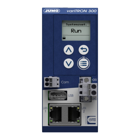
3 Elektrischer Anschluss 3.3.1 Anzeige-, Bedien- und Anschlusselemente Diese Übersicht zeigt die Lage der Anzeige-, Bedien- und Anschlusselemente. Die Zuordnung zu den einzelnen Funktionen ist in den folgenden Kapiteln dargestellt. (1) Antennenanschluss (2) Display (3) Bedienelemente (4) Spannungsversorgung DC 24 V (5) Schnittstelle LAN2 (6) Schnittstelle LAN1 (7) USB-Host-Schnittstelle... -
Page 26: Spannungsversorgung
3 Elektrischer Anschluss 3.3.3 Spannungsversorgung Anschluss Bezeich- Num- Symbol und Klemmenbezeichnung nung Spannungsver- +24 V und +24 V sorgung In 3.3.4 Abschlusswiderstände Werkseitig sind die Abschlusswiderstände der RS485-Schnittstelle deaktiviert. Zum Aktivieren müssen die Schalter 1 und 2 geschlossen werden. +5 V Die Schalter befinden sich innerhalb des Gehäuses und sind durch die Lüftungsschlitze (1) zugänglich. -
Page 27: Anhang
- E-Mail-Server - Modbus TCP Master/Slave - PROFINET IO Device - EtherCAT Slave - OPC UA Client - BACnet/IP Server/Client - JUMO Systembus über JUMO variTRON Routermodule (nur LAN2) Übertragungsrate 10 Mbit/s, 100 Mbit/s Anschlusskabel Netzwerkkabel, mindestens CAT5 (S/FTP) Kabellänge... -
Page 28: Anzeige
Übertragung Der RSSI-Wert ist ein Indikator für die Stärke des Empfangssignals (theoretischer Wertebereich: -120 bis 0). Einsatz Empfänger für JUMO Wtrans-Sender (drahtlose Messwertübertra- gung) Kompatible Sender Wtrans T (902930), Wtrans B (707060), Wtrans p (402060), Wtrans E01 (902928) ab Systemversion 6 Nicht unterstützte Thermoelement-Typen bei Wtrans B:... -
Page 29: Elektrische Daten
4 Anhang 4.1.3 Elektrische Daten Spannungsversorgung (Klemmen +24 V und GND) Symbol (siehe Typenschild) Anschluss frontseitig (abnehmbare Klemmleiste 2-polig mit Push-In-Technolo- gie) Spannung DC 24 V +25/-20 % SELV Restwelligkeit Stromaufnahme max. 280 mA (bei DC 19,2 V) Leistungsaufnahme max. 5,6 W Leiterquerschnitt an Klemmen +24 V und Draht oder Litze ohne Aderendhülse min. -
Page 30: Gehäuse Und Umgebungsbedingungen
4 Anhang 4.1.4 Gehäuse und Umgebungsbedingungen Gehäuseart Kunststoffgehäuse für Hutschienenmontage im Schaltschrank (Ver- wendung in Innenräumen); Hutschiene nach DIN EN 60715, 35 mm x 7,5 mm x 1 mm Abmessungen (B × H × T) 45 mm × 101 mm × 101,5 mm (ohne Anschlusselemente) Gewicht (voll bestückt, inkl. -
Page 31: Open-Source-Software
Soweit die jeweils anwendbaren Lizenzbedingungen einen Anspruch auf die Bereitstellung des Quell- codes oder sonstiger Informationen begründen, stellt JUMO GmbH & Co. KG den Quellcode und die Lizenztexte auf einem üblichen Datenträger zum Preis, der für die Erstellung des Datenträgers anfällt, zur Verfügung. -
Page 32: China Rohs
4 Anhang China RoHS... - Page 34 JUMO GmbH & Co. KG Moritz-Juchheim-Straße 1 Technischer Support Deutschland: 36039 Fulda, Germany Telefon: +49 661 6003-727 Telefon: +49 661 6003-9135 Telefax: +49 661 6003-508 Telefax: +49 661 6003-881899 E-Mail: mail@jumo.net E-Mail: support@jumo.net Internet: www.jumo.net Lieferadresse: Mackenrodtstraße 14 36039 Fulda, Germany...
-
Page 35: Installation Instructions
JUMO variTRON 300 Automation System Central Processing Unit 705003 Installation Instructions 70500300T94Z000K000 EN/00731924... - Page 36 Further information and downloads qr-705003-en.jumo.info...
- Page 37 Contents Contents Introduction ..........5 Safety information .
- Page 38 Contents 4.1.4 Housing and environmental conditions .........28 4.1.5 Approvals and approval marks .
-
Page 39: Introduction
Introduction 1 Introduction Safety information General This manual contains information that must be observed in the interest of your own safety and to avoid material damage. This information is supported by symbols which are used in this manual as indicated. Please read this manual before starting up the device. -
Page 40: Intended Use
1 Introduction Intended use The device is designed for use in an industrial environment as specified in the technical data. Other uses beyond those defined are not viewed as intended uses. The device has been manufactured in compliance with applicable standards and directives as well as the applicable safety regulations. -
Page 41: Acceptance Of Goods, Storage, And Transport
Description of the error that has occurred The accompanying letter for repair (supplementary sheet for product returns) can be downloaded online from the manufacturer's website: http://productreturn.jumo.info Protection against electrostatic discharge (ESD) (ESD = electrostatic discharge) To prevent damage due to ESD, electronic modules or components must be handled, packaged, and stored in an ESD-protected environment. -
Page 42: Disposal
1 Introduction 1.4.4 Disposal Disposing of the packaging material The entire packaging material (cardboard packaging, inserts, plastic film, and plastic bags) is fully recy- clable. The country-specific laws and regulations for waste treatment and disposal must be observed. Disposing of the device DISPOSAL! Devices and/or replaced parts (including batteries) should not be placed in the refuse bin at the end of their service life, but must be disposed of properly and in an environmentally friendly manner. -
Page 43: Identifying The Device Version
1 Introduction Identifying the device version 1.5.1 Nameplate Position The nameplate (A) is affixed to the module case. Table of contents The nameplate contains important information. This includes: Description Designation on the Example nameplate Device type Type 705003/01008-00-36/000.224 Part no. 00123456 Fabrication number F-Nr. -
Page 44: Order Details
(extra codes) simultaneously, depending on the application. As a more powerful device, the JUMO variTRON 500 central processing unit (type 705002) is available. Your contact person in Technical Sales will be happy to advise you on selecting the appropriate central processing unit for your application. -
Page 45: Scope Of Delivery
1 Introduction List further extra codes in sequence, separated by commas. 1.5.3 Scope of delivery 1 central processing unit, type 705003, in the ordered version 1 lambda/4-antenna (only for device with wireless interface) 1 installation instructions 1.5.4 Accessories Designation Part no. RJ45 patch cable SF/UTP, length 0.3 m 00747472 Antenna cable, length 1 m, impedance 50 ohm with preconfigured screw-type connec-... -
Page 46: Available Technical Documentation
The documentation for the automation system is addressed to plant manufacturers and users with spe- cialist training and consists of the following documents (previous document number in brackets). 1.6.1 Central processing unit Product Document Printed PDF file variTRON 300 Data sheet 70500300T10... Operating manual 70500300T90... Central processing unit Installation instructions 70500300T94... -
Page 47: Special Modules
70504300T10... 1-port Installation instructions 70504300T94... (as of system version 4) 1.6.4 Panels Product Document Printed PDF file JUMO variTRON Data sheet 70507000T10... Web panels 1.6.5 Power supply units Product Document Printed PDF file 24 V power supply Data sheet 70509000T10... - Page 48 1 Introduction...
-
Page 49: Mounting
Mounting 2 Mounting General information on installation/dismounting DANGER! With multichannel controller module 705010 and relay module 705015, the load circuits from re- lay or solid state relay outputs can be operated with a dangerous electrical voltage (e.g. 230 V). There is a risk of electric shock. ... -
Page 50: Installation/Dismounting On Din Rail
2 Mounting Minimum distances NOTE! The upper minimum distance 35 mm is sufficient to connect a cable to the antenna socket. If the antenna is connected directly to the antenna socket, a minimum distance of 100 mm is required. Installation/dismounting on DIN rail All modules in the system are intended for installation on a DIN rail according to DIN EN 60715 (35 mm ×... - Page 51 2 Mounting Installation of the central processing unit 705003 (A1) (A2) Process: 1. Mount the central processing unit (A) on the DIN rail from above (A1). 2. Pivot the central processing unit (A) downwards until it snaps into place (A2). NOTE! If necessary, activate the terminating resistors of the RS485 interface before installation (see chapter "Electrical connection")!
- Page 52 2 Mounting Dismounting of the central processing unit 705003 (A4) (B1) (A2) (C3) Process: 1. Remove the connecting cables if required (interfaces). 2. If required, use a screwdriver to release the wired terminal (B) of the central processing unit (A) and pull off toward the front (B1).
-
Page 53: Dimensions
2 Mounting Dimensions 17.5 94.5 101.5... - Page 54 2 Mounting...
-
Page 55: Electrical Connection
Electrical connection 3 Electrical connection Installation notes NOTE! These installation notes apply for the entire automation system and, on some occasions, are only appli- cable for a specific module. The respective connection diagram shows the context. Requirements for personnel • Work on the modules must only be carried out to the extent described and, like the electrical con- nection, only by qualified personnel. -
Page 56: Galvanic Isolation
3 Electrical connection Galvanic isolation Interface LAN1 Interface LAN2 Interface COM Interface USB host Voltage supply In (1) Functional galvanic isolation for connection of SELV or PELV electrical circuits. Connection diagram CAUTION! At maximum load, the temperature may exceed 60 °C at the terminals "+24 V" and "GND" (voltage supply In). -
Page 57: Display, Operating, And Connection Elements
3 Electrical connection 3.3.1 Display, operating, and connection elements This overview shows the position of the display, operating, and connection elements. The assignment to individual functions is illustrated in the following sections. (1) Antenna connector (2) Display (3) Control elements (4) Voltage supply DC 24 V (5) Interface LAN2 (6) Interface LAN1... -
Page 58: Voltage Supply
3 Electrical connection 3.3.3 Voltage supply Connection Designa- Num- Symbol and terminal designation tion Voltage supply In +24 V and +24 V 3.3.4 Terminating resistors The terminating resistors of the RS485 interface are deactivated per default. To activate them, switches 1 and 2 must be closed. -
Page 59: Annex
- Modbus TCP master/slave - PROFINET IO device - EtherCAT slave - OPC UA client - BACnet/IP server/client - JUMO system bus via JUMO variTRON router modules (LAN2 only) Transfer rate 10 Mbit/s, 100 Mbit/s Connecting cable Network cable, at least CAT5 (S/FTP) -
Page 60: Display
The RSSI value is an indicator of the strength of the received signal (theoretical value range: -120 to 0). Application Receiver for JUMO Wtrans transmitters (wireless transmission of measured values) Compatible transmitters Wtrans T (902930), Wtrans B (707060), Wtrans p (402060),... -
Page 61: Electrical Data
4 Annex 4.1.3 Electrical data Voltage supply (terminals +24 V and GND) Symbol (see nameplate) Connection At the front (removable terminal strip, 2-pole with PUSH IN technolo- Voltage DC 24 V +25/-20 % SELV Residual ripple Current consumption Max. 280 mA (at DC 19.2 V) Power consumption Max. -
Page 62: Housing And Environmental Conditions
4 Annex 4.1.4 Housing and environmental conditions Case type Plastic case for DIN rail mounting in the control cabinet (indoor use); DIN rail acc. to DIN EN 60715, 35 mm × 7.5 mm × 1 mm Dimensions (W × H × D) 45 mm ×... -
Page 63: Open-Source Software
Insofar as the respectively applicable license terms justify a claim on the provision of source codes or other information, JUMO GmbH & Co. KG will provide the source code and the license texts on a con- ventional data carrier at the cost incurred by creating the data carrier. -
Page 64: China Rohs
4 Annex China RoHS... - Page 66 JUMO GmbH & Co. KG JUMO Instrument Co. Ltd. JUMO Process Control, Inc. Street address: JUMO House 6733 Myers Road Moritz-Juchheim-Straße 1 Temple Bank, Riverway East Syracuse, NY 13057, USA 36039 Fulda, Germany Harlow, Essex, CM20 2DY, UK Delivery address:...
- Page 67 JUMO variTRON 300 Système d'automatisation Unité centrale 705003 Notice de montage 70500300T94Z000K000 FR/00731924...
- Page 68 Informations complémentaires et téléchargements qr-705003-fr.jumo.info...
- Page 69 Sommaire Sommaire Introduction ..........5 Instructions relatives à...
- Page 70 Sommaire 4.1.4 Boîtier et conditions ambiantes..........28 4.1.5 Homologations et marques de contrôle .
-
Page 71: Introduction
Introduction 1 Introduction Instructions relatives à la sécurité Généralités Cette notice contient des instructions dont vous devez tenir compte aussi bien pour assurer votre propre sécurité que pour éviter des dégâts matériels. Ces instructions sont appuyées par des pictogrammes et sont utilisées dans cette notice comme indiqué. -
Page 72: Utilisation Conforme Aux Prescriptions
1 Introduction Utilisation conforme aux prescriptions L'appareil est conçu pour une utilisation dans un environnement industriel, comme spécifié dans les ca- ractéristiques techniques des différents modules du système. Toute autre utilisation ou hors de ce cadre est considérée comme non conforme. L'appareil est fabriqué... -
Page 73: Réception Du Matériel, Stockage Et Transport
Il est possible de télécharger le bordereau de réparation (Supplementary sheet for product returns) sur la page d'accueil Internet du fabricant : http://productreturn.jumo.info Protection contre les décharges électrostatiques (ESD) (ESD = Electro Static Discharge) Pour éviter les dommages dus aux décharges électrostatiques, il faut manipuler, emballer et stocker les modules ou composants électroniques dans un environnement protégé... -
Page 74: Traitement Des Déchets
1 Introduction 1.4.4 Traitement des déchets Evacuation des matériaux d'emballage L'ensemble du matériel d'emballage est totalement recyclable (cartonnage, papier, film et sac en plas- tique). Respectez les lois et prescriptions de votre pays en matière d'évacuation et de traitement des déchets. Evacuation de l'appareil TRAITEMENT DES DECHETS ! Cet appareil et les pièces remplacées (piles comprises) ne doivent pas être jetés à... -
Page 75: Identification De L'exécution De L'appareil
1 Introduction Identification de l'exécution de l'appareil 1.5.1 Plaque signalétique Position La plaque signalétique (A) est collée sur le boîtier du module. Sommaire La plaque signalétique contient des informations importantes. Il s'agit entre autres de : Description Désignation sur la Exemple plaque signalétique Type d'appareil... -
Page 76: Références De Commande
être impossible d'utiliser toutes les fonctions (options) simultanément, selon l'application. L'uni- té centrale JUMO variTRON 500 (type 705002) est disponible en tant qu'appareil plus performant. Votre interlocuteur technico-commercial se fera un plaisir de vous conseiller sur le choix de l'unité cen- trale la plus adaptée à... -
Page 77: Matériel Livré
1 Introduction (2) (3) (4) (5) (10) Code de 705003 / 0 0 - 8 - 00 - 36 / 000 , 224 , ... com- mande Exemple 705003 / 0 0 - 8 - 00 - 36 / 000 , 224 de com- mande Enumérer les autres options séparées par une virgule. -
Page 78: Documentation Technique Disponible
(ancien numéro de do- cument entre parenthèses). 1.6.1 Unité centrale Produit Document N° sur papier fichier variTRON 300 Fiche technique 70500300T10... Notice de mise en service 70500300T90... Unité centrale Notice de montage 70500300T94... -
Page 79: Modules Spéciaux
Notice de montage 70504300T94... (à partir de la ver- sion système 4) 1.6.4 Panels (écrans) Produit Document N° sur papier fichier JUMO variTRON Fiche technique 70507000T10... Ecrans Web 1.6.5 Blocs d'alimentation Produit Document N° sur papier fichier Alimentations 24 V Fiche technique 70509000T10... - Page 80 1 Introduction...
-
Page 81: Montage
Montage 2 Montage Généralités sur le montage/démontage DANGER! Sur le module régulateur multicanal 705010 et le module relais 705015, les circuits de charge des sorties à relais ou relais statiques peuvent être alimentés avec une tension électrique dange- reuse (par ex. 230 V). Il y a un risque de choc électrique. -
Page 82: Montage/Démontage Sur Rail Din
2 Montage Ecarts minimaux REMARQUE ! La distance minimale supérieure de 35 mm est suffisante pour connecter un câble à la prise de l'an- tenne. Si l'antenne est branchée directement à la prise d'antenne, une distance minimale de 100 mm est requise. - Page 83 2 Montage Montage de l'unité centrale 705003 (A1) (A2) Instructions : 1. Accrocher l'unité centrale (A) par le haut sur le rail symétrique (A1). 2. Basculer l'unité centrale vers le bas jusqu'à encliquetage (A2). REMARQUE ! Si nécessaire, activez les résistances de terminaison de l'interface RS485 avant le montage (voir cha- pitre "Raccordement électrique") !
- Page 84 2 Montage Démontage de l'unité centrale 705003 (A4) (B1) (A2) (C3) Instructions : 1. Le cas échéant, déconnecter les câbles de raccordement (ports). 2. Le cas échéant, avec un tournevis dévisser les bornes câblées (B) de l'unité centrale (A) et tirer vers l'avant (B1).
-
Page 85: Dimensions
2 Montage Dimensions 17.5 94.5 101.5... - Page 86 2 Montage...
-
Page 87: Raccordement Électrique
Raccordement électrique 3 Raccordement électrique Instructions relatives à l’installation REMARQUE ! Ces instructions relatives à l'installation s'appliquent à l'ensemble du système d'automatisation ; elles ne sont valables partiellement que pour certains modules. Voir également le schéma de raccordement. Exigences vis à vis du personnel •... -
Page 88: Séparation Galvanique
3 Raccordement électrique Avertissements complémentaires • La compatibilité électromagnétique correspond aux normes et règlements mentionnés dans les ca- ractéristiques techniques. • Dans certains cas le port USB et l'alimentation ne sont pas séparés galvaniquement. Respectez d'une manière générale les instructions sur la séparation galvanique. Séparation galvanique Port LAN1 Port LAN2... -
Page 89: Eléments D'affichage, De Commande Et De Raccordement
3 Raccordement électrique 3.3.1 Eléments d'affichage, de commande et de raccordement Cette vue d'ensemble montre la position des éléments d'affichage, de commande et de raccordement. L'affectation aux différentes fonctions est décrite dans les chapitres qui suivent. (1) Branchement d'antenne (2) Ecran (3) Eléments de commande (4) Alimentation DC 24 V (5) Port LAN2... -
Page 90: Alimentation
3 Raccordement électrique Raccordement Désigna- Numé- Elément de raccorde- Affectation tion ment Port série RS485 COM Bornier 2 pôles 1 TxD+/RxD+ Emission/réception de données + 2 TxD-/RxD- Emission/réception de données - 3.3.3 Alimentation Raccordement Désigna- Numé- Symbole et repérage des bornes tion Alimentation In +24 V et... -
Page 91: Annexe
- Modbus TCP Master/Slave - PROFINET IO Device - EtherCAT Slave - OPC UA Client - BACnet/IP Server/Client - bus système de JUMO via le module routeur JUMO variTRON (uni- quement LAN2) Vitesse de transmission 10 Mbit/s, 100 Mbit/s Câble de raccordement Câble pour réseau, au minimum CAT5 (S/FTP) -
Page 92: Afficheur
La valeur RSSI est un indicateur de la force du signal reçu (plage de valeurs théorique : -120 à 0). Utilisation Récepteur pour les émetteurs JUMO Wtrans (transmission sans fil des valeurs mesurées) Emetteurs compatibles Wtrans T (902930), Wtrans B (707060), Wtrans p (402060), Wtrans E01 (902928) à... -
Page 93: Caractéristiques Électriques
4 Annexe 4.1.3 Caractéristiques électriques Alimentation (bornes +24 V et GND) Symbole (voir plaque signalétique) Raccordement Sur la face avant (bornier amovible, à 2 pôles, avec technologie Push Tension DC 24 V +25/-20 % SELV Ondulation résiduelle Puissance absorbée Max. 280 mA (si 19,2 V DC) Puissance absorbée Max. -
Page 94: Boîtier Et Conditions Ambiantes
4 Annexe 4.1.4 Boîtier et conditions ambiantes Type de boîtier Boîtier en matière synthétique pour montage sur rail DIN dans une armoire de commande (utilisation en intérieur) ; rail DIN suivant DIN EN 60715, 35 mm x 7,5 mm x 1 mm Dimensions (l x h x p) 45 mm ×... -
Page 95: Logiciel Open Source
Dans la mesure où les conditions de licence applicables justifient la mise à disposition du code source ou d'autres informations, JUMO GmbH & Co. KG fournit le code source et les textes de licence sur un support conventionnel, au coût supporté pour la création du support de données. -
Page 96: China Rohs
4 Annexe China RoHS... - Page 98 JUMO GmbH & Co. KG Adresse : Moritz-Juchheim-Straße 1 36039 Fulda, Allemagne Adresse de livraison : Mackenrodtstraße 14 36039 Fulda, Allemagne Adresse postale : 36035 Fulda, Allemagne Téléphone : +49 661 6003-0 Télécopieur : +49 661 6003-607 E-Mail: mail@jumo.net Internet: www.jumo.net...