Table des Matières
Publicité
Les langues disponibles
Les langues disponibles
Liens rapides
EN
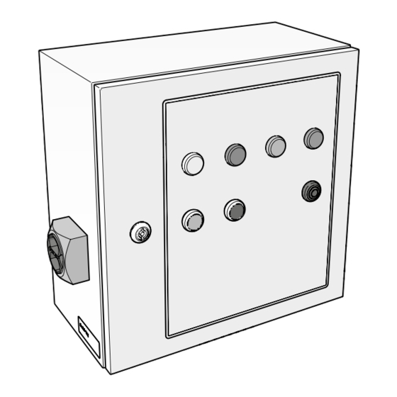
Control panel
NL
Besturingskast
DE
Steuerungskasten
FR
Armoire de contrôle
ES
Armario de control
coNtRoLGo
EN
Installation and user manual
NL
Installatie- en gebruikershandleiding
DE
Installations- und Betriebsanleitung
FR
Manuel d'installation et d'utilisation
ES
Manual de instalación y de uso
www.plymovent.com
Publicité
Table des Matières

Manuels Connexes pour PLYMOVENT controlGo


Sommaire des Matières pour PLYMOVENT controlGo
- Page 1 Control panel Besturingskast Steuerungskasten Armoire de contrôle Armario de control coNtRoLGo Installation and user manual Installatie- en gebruikershandleiding Installations- und Betriebsanleitung Manuel d’installation et d’utilisation Manual de instalación y de uso www.plymovent.com...
- Page 2 Ud. Esta publicación se ha escrito con sumo cuidado. Sin embargo, no se podrá responsabilizar al fabricante ni por los errores que haya en esta publicación ni por sus consecuencias. 0000112607/170717/0 ControlGo...
-
Page 3: Table Des Matières
Instalación Mise en service Puesta en servicio Utilisation Entretien Mantenimiento Réparation des pannes Subsanación de fallos Pièces détachées Piezas de recambio 10. Schéma électrique 10. Esquema eléctrico 11. Mettre au rebut 11. Desechar Déclaration de Conformité Declaración CE 0000112607/170717/0 ControlGo... -
Page 4: Preface
- power consumption configuration Fan control equipment General description Recommended way: ControlGo of Plymovent is an intelligent control panel, - Plymovent VFD/Panel3 specific type depends on the including the required connection cables. This system controls (frequency inverter) selected extraction fan... -
Page 5: Options And Accessories
Connection cables ambient conditions Cables to connect the Panel to the SlaveBoard(s). 1.6.1 ControlGo/Panel Operation ControlGo is an intelligent platform that controls a filter Pressure sensors: system MDB, SCS or EDS and the connected extraction fan. It Ambient temperature: internal external monitors the availability of compressed air and arranges the - min. -
Page 6: Safety Instructions
30 running hours of the system, three offline filter cleaning cycles take place. SaFEty iNStRUctioNS General The ControlGo is delivered as part of a filter system MDB, SCS or EDS of Plymovent. The safety instructions written in the related manuals apply to the ControlGo as well. [cable #1]... -
Page 7: Electric Connection
Mounting attENtioN Do not expose any component of ControlGo to vibrations or heat radiation. You must install the Panel at a clearly visible and accessible position. 4.3.1 ControlGo/Panel Fig. 4.4 Bottom plate To install the Panel, do the following. Table I on page 77 gives an overview of the necessary and Fig. - Page 8 Panel. • Connect the mains cable to the terminal block (A). • Tighten the cable gland. 14. Recommended cable specifications; use cables with a max. wire diameter 1,5 mm² (AWG 16) 15. Size M20 0000112607/170717/0 ControlGo EN - 7...
-
Page 9: Fan Control
- other type of frequency inverter (third party) cable #1 - star-delta switch - other type of motor starter, e.g. Direct online (DOL) For more information about the Plymovent VFD/ Panel, refer to the Danfoss documentation that is supplied with the product. Connections/functionalities: - relay output (potential-free contact) for start/stop signal - alarm input;... - Page 10 DIP switches. Fig. 4.11 SlaveBoard SlaveBoard 17. Address configuration pos. 1-4: according to number 1 18. Supplied with Panel to SlaveBoards cable (#1) 19. The red module on the PC board 0000112607/170717/0 ControlGo EN - 9...
- Page 11 Valves 1 2 3 4 5 6 7 8 9 10 11 12 13 14 15 16 Digital input 6-12 If desired, you can connect the ControlGo to a start/stop signal 1 2 3 4 5 6 Valves Indicator LED’s...
- Page 12 Sliding valve feedback 1 IN 11 E Fig. 4.21 Connection of pneumatic hoses to the Panel IN 4 Spare IN 8 Sliding valve feedback 2 IN 12 D 23. E.g. a roof fan 24. Type PT-2500 0000112607/170717/0 ControlGo EN - 11...
-
Page 13: Commissioning
SCS systems (master/slave). 5.3.3 SCS (two filter systems) attENtioN ControlGo Panels are factory-wise prepared for use • Follow the flowchart SCS (#2) on page 81. with either MDB or SCS / EDS filter systems. They are not interchangeable. -
Page 14: Maintenance
40 running hours after filter replacement, to maintain the protective 33. The filter cleaning system continues to run. Push the black button again or put layer of precoat material on the filter cartridges the Panel in Normal Mode to stop it. 0000112607/170717/0 ControlGo EN - 13... -
Page 15: Troubleshooting
- Replace the filter extraction are clogged cartridges (refer Firmware capacity to the MDB/SCS/ EDS manual) The latest firmware version is available on the Plymovent FILTERS VERSTOPT GEEN PERSLUCHT - Reset the precoat extranet. FILTERS CLOGGED NO COMPRESSED AIR COMMUNICATION ERRO FILTER GESÄTTIGT... -
Page 16: Spare Parts
Repair or replace ENTILATOR-/MOTORSTORING EXTERN APPARAAT EXTERNAL DEVICE 0000113558 Indicator light yellow 24V the fan control ENTILATOR-/MOTOR-AUSFALL EXTERNES GERÄT equipment 0000113631 PCB main board ControlGo/MDB ÉFAUT MOTEUR/VENTILATEUR DISPOSITIF EXTERNE FILTER CLEANING External Repair the 0000113632 PCB main board ControlGo/SCS-EDS device communication connection... -
Page 17: Preface
DEcLaRatioN CE Declaration of Conformity for machinery We, Plymovent Manufacturing B.V., Koraalstraat 9, 1812 RK Alkmaar, the Netherlands, herewith declare, on our own responsibility, that the product: - ControlGo which this declaration refers to, is in accordance with the... -
Page 18: Identificatie Van Het Product
Montageframe algemene beschrijving - Plymovent FRAME SIF specifieke type is afhankelijk van ControlGo van Plymovent is een intelligent bedieningspaneel, de geselecteerde ventilator en de dat wordt geleverd inclusief de benodigde aansluitkabels. Dit configuratie systeem regelt de besturing van persluchtkleppen van het aangesloten filtersysteem MDB, SCS of EDS en de ventilator. -
Page 19: Opties En Accessoires
Ventilatorbesturing Aanbevolen manier: 1.6.1 ControlGo/Panel - Plymovent VFD/Panel3 het specifieke type is afhankelijk (frequentieregelaar) van de geselecteerde ventilator Druksensors: Andere opties: Bedrijfstemperatuur: intern extern - Ander type frequentie- ventilator aan/uit met optionele - min. 0°C -20°C regelaar (door derden alarm feedback - nom. -
Page 20: Veiligheidsvoorschriften
SlaveBoard(s). VEiLiGhEiDSVooRSchRiFtEN Werking ControlGo is een intelligent platform voor de bediening van algemeen een filtersysteem MDB, SCS of EDS en de aangesloten De ControlGo wordt geleverd als onderdeel van een afzuigventilator. Het controleert de aanwezigheid van perslucht filtersysteem MDB, SCS of EDS van Plymovent. - Page 21 (2) voor de drukslangen [kabel #1] [kabel #2] Fig. 4.1 Aansluitkabels installatie LEt op Zorg ervoor dat de componenten van ControlGo niet aan trillingen of hittestraling worden blootgesteld. Het Panel moet op een duidelijk zichtbare en bereikbare plaats worden geïnstalleerd. Fig. 4.4 Bodemplaat 4.3.1...
-
Page 22: Elektrische Aansluiting
- Zie Table II op pagina 78 voor een specificatie van de digitale ingangen (hoog/laag). Afneembaar klemmenblok met schroefaansluiting (“connector”) Draadbruggen De printplaat is voorzien van een aantal draadbruggen. 14. Aanbevolen kabelspecificaties; gebruik kabels met een max. draaddiameter van 1,5 mm² 0000112607/170717/0 ControlGo NL - 21... - Page 23 Opmerking Voor meer informatie over de Plymovent VFD/Panel, zie de meegeleverde productdocumentatie van Danfoss. Digital input 1-5 Digital input 1-5 1 2 3 4 5 6 7 8 9 10 11 12 Aansluitingen/functionaliteiten: 1 2 3 4 5 6 7 8 9 10 11 12...
- Page 24 In geval van meerdere filtermodules moet u de kabels in serie aansluiten. Addressing Address configuration: sequence: 18. Meegeleverd met de Panel SlaveBoard kabel (#2) 17. Adresconfiguratie positie 1-4: volgens nummer 1 19. De rode module op de printplaat 0000112607/170717/0 ControlGo NL - 23...
-
Page 25: Address Configuration
20. Ga verder met paragraaf 4.4.6 in geval van een SCS 21. Het systeem geeft een waarschuwing wanneer er geen perslucht beschikbaar is Digital input 6-12 0000112607/170717/0 ControlGo NL - 24 1 2 3 4 5 6 7 8 9 10 11 12 13 14 15 16... - Page 26 • Sluit de tweede SCS aan op uitgang OUT 2. 4.4.7 Ingangssignalen (opties) ( rmware updates) Desgewenst kunt u de ControlGo op een start/stop-signaal en/ of een alarmsignaal van een extern apparaat aansluiten; ( rmware updates) Ethernet Digital input 6-12...
-
Page 27: Checklist Voor Ingebruikname
SCS- / EDS-filtersysteem, zie de betreffende systemen met twee geschakelde SCS’en (master/slave). handleiding. LEt op ControlGo Panels zijn fabrieksmatig voorbereid voor gebruik met óf MDB- óf SCS / EDS-filtersystemen. Ze zijn niet uitwisselbaar. In geval van: - één SCS-systeem; of... -
Page 28: Gebruik
- LED brandt: het systeem is bedrijfsgereed 29. In de servicemodus kunt u de ventilator en het filtersysteem alleen handmatig activeren Groene LED | VENTILATOR DRAAIT 30. Nadraaitijd: 3 minuten voor het afzuigen van eventueel rookresidu 0000112607/170717/0 ControlGo NL - 27... -
Page 29: Filterreiniging
NO COMPRESSED AIR COMMUNICATION ERROR FILTER GESÄTTIGT KEINE DRUCKLUFT KOMMUNIKATIONSFEHLER SERVICE MODE Communicatiefout • Neem contact op met uw Plymovent distributeur voor het GEEN PERSLUCHT COMMUNICATIEFOUT SERVICEMODUS FILTRES OBSTRUÉS ABSENCE D’AIR COMPRIMÉ ERREUR DE COMMUNICATION verkrijgen van de laatste firmware-versie. -
Page 30: Verhelpen Van Storingen
- het Panel herkent de USB stick niet kabel(s) (kabel - de USB stick bevat files die niet voor het #1 of #2) ControlGo Panel bedoeld zijn Printplaat in Vervang de Het systeem gaat terug naar de normale modus. STORING... -
Page 31: Reserveonderdelen
Leermodus (zie par. 5.3) EG-verklaring van overeenstemming Softwarefout - Probeer het tijdens systeem te Wij, Plymovent Manufacturing B.V., Koraalstraat 9, 1812 RK opstarten van herstarten Alkmaar, Nederland, verklaren geheel onder eigen het systeem - Anders: neem verantwoordelijkheid dat het product:... -
Page 32: Identifizierung Des Produktes
Beschreibung - Plymovent FRAME SIF der spezifische Typ hängt vom gewählten Absaugventilator und Das ControlGo von Plymovent ist ein intelligenter der Konfiguration ab Steuerungskasten, das mit den benötigten Anschlusskabeln geliefert wird. Dieses System steuert den Ventilator und die Druckluftventile des angeschlossenen Filtersystems (MDB, SCS bzw. -
Page 33: Optionen Und Zubehör
Genehmigungen & Ventilatorsteuerung Zertifikate Bevorzugte Weise: - Plymovent VFD/Panel3 der spezifische Typ hängt vom Umgebungsbedingungen (Frequenzumrichter) gewählten Absaugventilator ab Andere Optionen: 1.6.1 ControlGo/Panel - Anderer Typ von Ventilatorbetrieb starten/stoppen Frequenzumrichter ausschließlich mit optionalem Drucksensoren: (Dritter) Alarm-Feedback Betriebstemperatur: intern: extern: - Sterndreieckschalter Ventilator ein/aus ausschließlich... -
Page 34: Sicherheitsvorschriften
- manuell (über die Drucktasten des Bedienfelds) Das Produkt wurde ausschließlich als Steuerungsanlage für ein - automatisch (über Signale eines externen Geräts) Filtersystem Typ MDB bzw. SCS / EDS von Plymovent und das angeschlossene Absaugventilator entworfen. Fig. 1.1 und Fig. 1.2 verdeutlichen den Anschluss der Jede andere oder darüber hinausgehende Benutzung gilt nicht... -
Page 35: Montage
Kabelverschraubungen M16 (6) Schottverbinder (2) für die Druckrohre [Kabel #1] [Kabel #2] Fig. 4.1 Anschlusskabel Montage achtUNG! ControlGo-Komponenten keinen Vibrationen oder Wärmestrahlen aussetzen! Das Panel muss an einem gut sichtbaren und zugänglichen Ort installiert werden Fig. 4.4 Bodenblech 4.3.1 ControlGo/Panel Table I auf Seite 77 bietet eine Übersicht über die... -
Page 36: Elektrischer Anschluss
- Table II auf Seite 78 bietet eine Spezifikation der Digitaleingänge (hoch/niedrig). Abnehmbarer Schraubklemmenblock („Steckverbinder”) Drahtbrücken Die Leiterplatte ist mit einer Anzahl von Drahtbrücken ausgestattet. 14. Empfohlene Kabelspezifikationen; Kabeln mit einem max. Durchmesser von 1,5 mm² verwenden 0000112607/170717/0 ControlGo DE - 35... - Page 37 Bemerkung Für weitere Informationen zum Plymovent VFD/ Panel siehe die mit dem Produkt mitgelieferte Digital input 1-5 Danfoss-Dokumentation. Digital input 1-5 1 2 3 4 5 6 7 8 9 10 11 12 1 2 3 4 5 6 7 8 9 10 11 12 Anschlüsse/Funktionalitäten:...
- Page 38 Address configuration: miteinander verbinden. Adressenkonfiguration von max. 16 Filtermodulen sequence: (=MDB-64). 18. Wird mit dem Kabel Panel SlaveBoard (#1) mitgeliefert 17. Adressenkonfiguration der Pos. 1-4: gemäß Nummer 1 19. Das rote Modul auf der Leiterplatte 0000112607/170717/0 ControlGo DE - 37...
- Page 39 (den Master) anschließen. 21. Wenn keine Druckluft zur Verfügung steht, gibt das System ein Warnsignal heraus Digital input 6-12 0000112607/170717/0 ControlGo DE - 38 1 2 3 4 5 6 7 8 9 10 11 12 13 14 15 16...
- Page 40 1 2 3 4 5 6 7 8 9 10 11 12 1 2 3 4 5 6 7 8 9 10 11 12 4.4.7 Eingangssignale (Optionen) ( rmware updates) Auf Wunsch kann an ControlGo ein Start-/Stopp-Signal und/ oder ein Alarmsignal eines externen Geräts angeschlossen ( rmware updates) Ethernet werden;...
- Page 41 Schottverbinder (B) anschließen. • Für einen Anschluss der Pneumatikschläuche an das achtUNG MDB- bzw. SCS / EDS-Filtersystem siehe entsprechende ControlGo-Panels sind werkseitig für einen Betrieb Anleitung. mit MDB- bzw. SCS-/EDS-Filtersystemen vorbe- reitet. Sie sind nicht miteinander austauschbar. Bei: - einem SCS-System; oder - einem EDS (Diluter) System mit Kapitel 6 weitergehen.
-
Page 42: Bedienung
Das Bedienfeld umfaßt folgende Bedienelemente und 26. Das System bleibt in Betrieb Kontrolllampen: 27. Das gesamte System stoppt 28. Die Ursache des Warnsignals ist noch nicht behoben 29. Im Service-Modus können Ventilator und Filtersystem ausschließlich von Hand aktiviert werden 0000112607/170717/0 ControlGo DE - 41... -
Page 43: Regelmäßige Wartung
Anleitungen. Filter gesättigt COMMUNICATION ERROR Keine Druckluft SERVICE MODE Firmware (Verzögerungszeit: 10 s) FILTERS VERSTOPT GEEN PERSLUCHT COMMUNICATIEFOUT Die neueste Firmware-Version ist im Plymovent-Extranet FILTER GESÄTTIGT KEINE DRUCKLUFT KOMMUNIKATIONSFEHLER SERVICE MODE Kommunikationsfehler verfügbar. GEEN PERSLUCHT COMMUNICATIEFOUT SERVICEMODUS FILTRES OBSTRUÉS ABSENCE D’AIR COMPRIMÉ... - Page 44 - Der Panel hat nicht den USB-Stick erkannt Kabel (Kabel bzw. austauschen - Der USB-Stick enthält Dateien, die nicht für #1 bzw. #2 STORING EXTERN APPARAAT den ControlGo-Panel bestimmt sind defekt -AUSFALL EXTERNES GERÄT Das System schaltet in den Leiterplatte in Leiterplatte(n)
-
Page 45: Eg-Konformitätserklärung
EG-KoNFoRMitätSERKLäRUNG (gelbe LED; siehe Abschnitt 6.3.1): EG-Konformitätserklärung für Maschinen Lernmodus- Prozedur wieder- holen (siehe Wir, Plymovent Manufacturing B.V., Koraalstraat 9, 1812 RK Abschnitt 5.3) Alkmaar, die Niederlande, erklären hiermit eigenverantwortlich dass das Produkt: Softwarefehler - Neustart des beim Systems... -
Page 46: Avant-Propos
- Plymovent FRAME SIF le type spécifique dépend du ventilateur sélectionné et la Le ControlGo de Plymovent est une armoire de contrôle, y configuration compris les câbles de connexion nécessaires. Ce système contrôle le ventilateur et les valves d’air comprimé du système de filtration MDB, SCS ou EDS connecté. -
Page 47: Options Et Accessoires
Préférence : 1.6.1 ControlGo/Panel - Plymovent VFD/Panel3 le type spécifique dépend du (frequency inverter) ventilateur sélectionné Autres options : Capteurs de pression : - Autre type du régulateur marche/arrêt du ventilateur Temp. de fonctionnement :... -
Page 48: Câbles De Connexion
MDB, Les Fig. 1.1 et Fig. 1.2 montrent la connexion des composants SCS et EDS de Plymovent avec le ventilateur d’aspiration de ControlGo avec le système de filtration et le ventilateur connecté. Tout autre usage est considéré comme non d’aspiration. - Page 49 [câble #1] [câble #2] pneumatiques Fig. 4.1 Câbles de connexion Montage attENtioN Ne jamais exposez les composants du ControlGo aux vibrations ou au rayonnement thermique. Le Panel doit être installé à un endroit bien visible et accessible 4.3.1 ControlGo/Panel Fig. 4.4 Plaque de fond Pour installer le Panel, procédez comme suit.
-
Page 50: Instructions Générales Pour Le Raccordement
Bornier à vis détachables (« connecteurs ») cavaliers Le circuit imprimé fourni avec un nombre de cavaliers. 14. Spécifications de câbles recommandées ; utilisez des câbles d’un diamètre de fil de max 1,5 mm² (AWG 16) 0000112607/170717/0 ControlGo FR - 49... -
Page 51: Connexion
Remarque ligne (DOL) Digital input 1-5 Pour plus d’information sur le Plymovent VFD/Panel, Digital input 1-5 consultez le manuel Danfoss fourni avec le produit. 1 2 3 4 5 6 7 8 9 10 11 12 1 2 3 4 5 6 7 8 9 10 11 12 Raccordements/fonctionnalités :... - Page 52 Assurez-vous que les commutateurs DIP sont placés correctement. • Fermez le couvercle 18. Livré avec le câble Panel SlaveBoard (#1) 17. Adressage de configuration pos. 1-4 : selon numéro 1 19. Le module rouge sur le circuit imprimé 0000112607/170717/0 ControlGo FR - 51...
- Page 53 1 2 3 4 5 6 7 8 9 10 11 12 13 14 15 16 1 2 3 4 5 6 7 8 9 10 11 12 13 14 15 16 21. Le système émet un signal d’avertissement lorsqu’il n’y a pas d’air comprimé disponible 0000112607/170717/0 ControlGo FR - 52 Digital input 6-12...
-
Page 54: Signals D'entrée (Options)
1 2 3 4 5 6 7 8 9 10 11 12 (for service only) 4.4.7 Signals d’entrée (options) Ethernet Au besoin, vous pouvez brancher le ControlGo à un signal (for service only) marche/arrêt et/ou un signal d’alarme d’un équipement NO 1 Valves Indicator LED’s... -
Page 55: Mise En Service
MDB et aux installations avec deux systèmes SCS connectés correspondant. (mâitre/esclave). attENtioN Les Panels ControlGo sont préparés en usine soit pour l’utilisation des systèmes de filtration MDB, soit SCS / EDS. Ils ne sont pas interchangeables. Filter Pressure En cas de : - un système de filtration SCS ;... -
Page 56: Utilisation
26. Le système continue à fonctionner suivantes : 27. Le ventilateur s’arrête de fonctionner 28. Vous devez encore résoudre la cause de l’avertissement 29. En Mode maintenance, vous pouvez uniquement activer le ventilateur et le système de filtration manuellement 0000112607/170717/0 ControlGo FR - 55... -
Page 57: Entretien
30. Temps de post-rotation : 3 minutes pour la suppression des fumées résiduelles, FAN/MOTOR FAILURE EXTERNAL DEVICE ERREUR DE COMMUNICATION MODE DE SERVICE • Contactez votre fournisseur Plymovent pour obtenir la le cas échéant SERVICE-MODUS FILTER CLEANING dernière version du firmware. ERROR DE COMUNICACIÓN MODO SERVICIO 31. -
Page 58: Réparation Des Pannes
- le Panel ne reconnait pas la clé USB les commutateurs DÉFAUT MOTEUR/VENTILATEUR DISPOSITIF EXTERNE - la clé USB contient des fichiers qui ne sont pas DIP sont placés destinés au Panel ControlGo FALLO DEL VENTILADOR/MOTOR DISPOSITIVO EXTERNO correctement AILURE EXTERNAL DEVICE Le système repasse en Mode normal. -
Page 59: External Device
DISPOSITIVO EXTERNO 0000103139 Alimentation à découpage 24V DC 2.5A fournisseur Plymovent 0000113558 Voyant lumineux jaune 24V 0000113631 Circuit imprimé carte maître ControlGo/MDB Autre réparation des pannes 0000113632 Circuit imprimé carte maître ControlGo/SCS-EDS 0040900180 Interrupteur principal 25A Signalisation problème cause Remède... -
Page 60: Déclaration De Conformité
DécLaRatioN DE coNFoRMité Déclaration CE de Conformité pour les machines Nous, soussignés, Plymovent Manufacturing B.V., Koraalstraat 9, 1812 RK Alkmaar, Pays-Bas, déclarons que le produit désigné ci-après : - ControlGo à lequelle la présente déclaration se rapporte, est conforme aux dispositions de la ou des Directives suivantes :... -
Page 61: Preámbulo
- Plymovent FRAME SIF el modelo específico depende del ventilador de aspiración El ControlGo de Plymovent es un panel de control inteligente seleccionado y la configuración que se entrega con los cables de conexión necesarios. Este sistema controla las válvulas de aire comprimido del sistema de filtración conectado MDB, SCS o EDS y el ventilador... -
Page 62: Opciones Y Accesorios
Aprobaciones & Equipo de control del ventilador certificados Método preferido: - Plymovent VFD/Panel3 el modelo específico depende del condiciones de entorno (variador de frecuencia) ventilador de aspiración seleccionado 1.6.1 ControlGo/Panel Otras opciones: - Otro modelo de variador arranque/parada del ventilador Sensores de presión:... -
Page 63: Normativas De Seguridad
ControlGo con el sistema de filtración y el ventilador de MDB GO, SCS GO y SCS GO de Plymovent con el ventilador de aspiración. aspiración conectado. Todo uso distinto o que vaya más allá de 2.2.1... -
Page 64: Cables De Conexión
[cable #1] [cable #2] Fig. 4.1 Cables de conexión Montaje ¡atENciÓN! No exponga componente alguno del ControlGo a vibraciones o radiación de calor. El armario Panel se deberá instalar en una posición claramente visible y accesible. Fig. 4.4 Placa de fondo Table I de la página 77 proporciona una panorámica de los... -
Page 65: Conexión Eléctrica
Bloque de terminales roscados desmontables (“conector”) Cables de puente La placa inteligente está provista de una serie de cables de puente. 14. Especificaciones de cable recomendadas: use cables con un diámetro de hilo máx. de 1,5 mm² (AWG 16) 0000112607/170717/0 ControlGo ES - 64... -
Page 66: Control Del Ventilador
Conexión Observación Para más información sobre el Plymovent VFD/ Panel, consulte la documentación de Danfoss que se suministra con el producto. Digital input 1-5 Digital input 1-5 1 2 3 4 5 6 7 8 9 10 11 12 Conexiones/funcionalidades: 1 2 3 4 5 6 7 8 9 10 11 12 - salida de relé... - Page 67 Addressing Address configuration: sequence: 18. Suministrado con el cable Panel SlaveBoard (#2) Addressing Address configuration: 17. Configuración de dirección pos. 1-4: conforme al número 1 19. El módulo rojo de la placa inteligente sequence: 0000112607/170717/0 ControlGo ES - 66...
-
Page 68: Interruptor + Válvula De Aire Comprimido Scs / Eds
20. Continúe con el apartado 4.4.6 en caso de un SCS 21. El sistema da una señal de advertencia cuando no se dispone de aire comprimido 0000112607/170717/0 ControlGo ES - 67 Digital input 6-12 1 2 3 4 5 6 7 8 9 10 11 12 13 14 15 16... - Page 69 22. P. ej. un robot de soldadura o un temporizador Digital input 6-12 23. P. ej. un ventilador de techo 24. Tipo PT-2500 1 2 3 4 5 6 7 8 9 10 11 12 13 14 15 16 0000112607/170717/0 ControlGo ES - 68...
-
Page 70: Puesta En Servicio
(A). ¡atENciÓN! • Para conectar las mangueras neumáticas al sistema de Los paneles del ControlGo se han preparado en filtración MDB o SCS / EDS, consulte el manual fábrica para que se usen con sistemas de filtración correspondiente. -
Page 71: Uso
28. Aún tendrá que resolver la causa de la alerta - DEL parpadeando: el sistema se está iniciando 29. En el Modo servicio, usted solo podrá activar el ventilador y el sistema de filtros manualmente 0000112607/170717/0 ControlGo ES - 70... -
Page 72: Limpieza De Filtros
ALARMA MODE DE SERVICE MODO SERVICIO • Póngase en contacto con el distribuidor de Plymovent para El DEL de alarma rojo - acompañado por el zumbador - puede obtener la última versión de firmware. mostrar dos patrones de parpadeo distintos:... -
Page 73: Subsanación De Fallos
EXTERNES GERÄT DIP tengan la - la memoria USB contiene archivos que no dirección correcta DÉFAUT MOTEUR/VENTILATEUR DISPOSITIF EXTERNE están destinados al Panel del ControlGo (véase Fig. 4.12 AILURE EXTERNAL DEVICE FALLO DEL VENTILADOR/MOTOR DISPOSITIVO EXTERNO El sistema vuelve al modo normal. -
Page 74: Piezas De Recambio
2.5A EXTERN APPARAAT Desconocida Desconocida Reinicie el sistema 0000113558 Luz indicadora amarilla 24V EXTERNES GERÄT 0000113631 Placa inteligente (placa maestra) ControlGo/MDB Póngase en + zumbador DISPOSITIF EXTERNE contacto con su 0000113632 Placa inteligente (placa maestra) ControlGo/SCS-EDS DISPOSITIVO EXTERNO distribuidor 0040900180... -
Page 75: Declaración Ce
DEcLaRaciÓN cE Declaración CE de Conformidad Los abajo firmantes, Plymovent Manufacturing B.V., Koraalstraat 9, 1812 RK Alkmaar, Países Bajos, declaran, bajo su exclusiva responsabilidad, que el producto: - ControlGo es conforme a las disposiciones de las: Directivas: - EMC 2014/30 EU | Directiva CEM - LVD 2014/35 EU | Directiva de baja tensión... - Page 76 Fig. I Dimensions Panel Fig. III SlaveBoard | PC board CAN IN CAN OUT 17.1 15.7 15.7 16.7 Fig. II SlaveBoards Fig. IV Connection sequence of SlaveBoards 0000112607/170717/0 ControlGo...
- Page 77 FAN/MOTOR FAILURE EXTERNAL DEVICE VENTILATOR-/MOTORSTORING EXTERN APPARAAT VENTILATOR-/MOTOR-AUSFALL EXTERNES GERÄT DÉFAUT MOTEUR/VENTILATEUR DISPOSITIF EXTERNE FALLO DEL VENTILADOR/MOTOR DISPOSITIVO EXTERNO 0000112512/A Fig. VI ControlPro/Panel 0000113631 0000103139 0000113632 0000113558 0324000310 0324000300 0324000320 0328050320 0328050300 0360000060 0040900180 Fig. VII Control/SlaveBoard 0000113561 0000112607/170717/0 ControlGo...
- Page 78 (Direktstarter) (démarreur direct en ligne) en línea) SCS-ventiel + SCS-Ventil + Druckschalter Électrovalve SCS + Válvula SCS + interruptor de persluchtschakelaar interrupteur à air comprimé aire comprimido Signaalzuil Signalampel Colonne lumineuse Luz de la torre de la señal 0000112607/170717/0 ControlGo...
- Page 79 Warnung normale alarme normal alarma wing IN 11 External alarm signal Extern alarmsignaal Externes Alarmsignal Signal d’alarme externe Señal de alarma externa normal alarm normaal alarm normal Alarm normal alarme normal alarma IN 12 n.a. n.v.t. no procede 0000112607/170717/0 ControlGo...
- Page 80 5.3.1 à la page 55 Modo de aprendizaje | Notas explicativas: consulte el apartado 5.3.1 de la página 69 0 = Service Mode 1 = Normal Mode FILTER CLEANING FILTER CLEANING Learning Mode activated SCS (#2) page 80 page 81 0000112607/170717/0 ControlGo...
- Page 81 FR Notices explicatives : reportez-vous à la section 5.3.2 à la page 55 Notas explicativas: consulte el apartado 5.3.2 de la página FILTER CLEANING 0 = Service Mode 1 = Normal Mode ≥5 s MDB-BM/2 MDB-BM/4 FILTER CLEANING <5 s MDB ready 0000112607/170717/0 ControlGo...
- Page 82 Seite 41 FR Notices explicatives : reportez-vous à la section 5.3.3 à la page 55 Notas explicativas: consulte el apartado 5.3.3 de la página SCS (#2) START/STOP FAN 0 = Service Mode 1 = Normal Mode SCS (#2) ready 0000112607/170717/0 ControlGo...
-
Page 83: Firmware Version
Anmerkungen: siehe Abschnitt 7.2 auf Seite 42 FR Mise à jour du firmware | Notices explicatives : reportez-vous à la section 7.2 à la page 56 Notas explicativas: consulte el apartado 7.2 de la página 71 Date Firmware version Firmware update ready 0000112607/170717/0 ControlGo... - Page 84 0000112607/170717/0 ControlGo www.plymovent.com...