
Manuels Connexes pour FS IES3100-8TF-P


Sommaire des Matières pour FS IES3100-8TF-P
- Page 1 IES3100-8TF-P L2+ MANAGED INDUSTRIAL SWITCH L2+ MANAGED INDUSTRIELLER SWITCH SWITCH INDUSTRIEL MANAGEABLE L2+ Quick Start Guide V1.0 Quick-Start Anleitung Guide de Démarrage Rapide...
- Page 2 Introduction Thank you for choosing IES3100-8TF-P managed switch. This guide is designed to familiarize you with the layout of the switch and describes how to deploy the switch in your network. IES3100-8TF-P Accessories Console Cable x 1 NOTE: IES3100-8TF-P switch has dust plugs delivered with it. Keep the dust plugs properly...
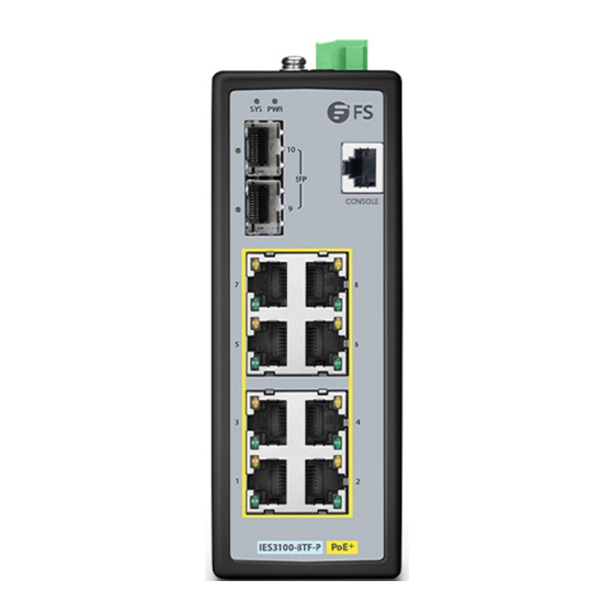
- Page 3 Hardware Overview Front Panel Ports 2x 100/1000/2500BASE-X SFP Ports 8x 10/100/1000BASE-T Ports CONSOLE Ports Description RJ45 10/100/1000BASE-T ports for Ethernet connection SFP ports for 100M/1G/2.5G connection CONSOLE A Mini USB console port for serial management Upper Panel Grounding Point Terminal Block Connector...
- Page 4 Rear Panel DIN-rail Mounting Kit Front Panel LEDs RJ45...
- Page 5 LEDs Status Description Power is being supplied to power input. Power is not being supplied to power input. Blinking The system is ready for operation. SYSTEM No supply voltage or the system is not ready for operation. A PoE terminal device is connected and receiving power via PoE. Yellow: PoE No PoE port available or Power over Ethernet function is disabled.
- Page 6 Mounting the Switch DIN-rail Mounting Mounting the unit Releasing the unit 1. Position the unit in front of the DIN-rail and hook the mount bracket over the top of the rail. 2. Rotate the switch downward towards the rail to lock it into place. You will know it is secure when you hear the click.
- Page 7 NOTE: This product is intended to be mounted to a well-grounded mounting surface such as a metal panel. Connecting the Power The Upper Panel of the switch indicates a DC inlet power socket and consists of one terminal block connector within 5 contacts. Please follow the steps below to insert the power wire. 1.
- Page 8 PWR1 PWR2 Positive (+) Pin Negative (-) Pin Pin 1 / 5 Pin 2 / 4 NOTE: The wire gauge for the terminal block should be in the range from 12 to 16 AWG. Connecting the RJ45 Ports 1. Connect an Ethernet cable to the RJ45 port of a camera, outdoor AP, computer or other network device.
- Page 9 Connecting the SFP Ports 1. Plug the compatible SFP transceiver into the SFP port. 2. Connect a ber optic cable to the ber transceiver. Then connect the other end of the cable to another ber device. Connecting the Console Port 1.
- Page 10 Con guring the Switch Con guring the Switch Using the Web-based Interface Step 1: Connect the computer to any RJ45 port of the switch using the network cable. Step 2: Set the IP address of the computer to 192.168.2.x (“x” is any number from 2 to 255). Step 3: Open a web browser, enter the default IP address of the switch 192.168.2.1, and enter the default username and password, admin/admin.
- Page 11 Contact Us Product Warranty FS ensures our customers that any damage or faulty items due to our workmanship, we will o er a free return within 30 Days from the day you receive your goods. This excludes any custom made items or tailored solutions.
- Page 12 Einführung Vielen Dank, dass Sie sich für den Managed Switch IES3100-8TF-P entschieden haben. Diese Anleitung soll Sie mit dem Aufbau des Switches vertraut machen und beschreibt, wie Sie den Switch in Ihrem Netzwerk einsetzen. IES3100-8TF-P Zubehör Console-Kabel x 1 HINWEIS: Beim Switch IES3100-8TF-P werden Staubschutzkappen mitgeliefert.
- Page 13 Hardware-Übersicht Ports an der Vorderseite 2x 100/1000/2500BASE-X SFP Ports 8x 10/100/1000BASE-T Ports CONSOLE Ports Beschreibung RJ45 10/100/1000BASE-T Ports für Ethernet-Anschluss SFP Ports für 100M/1G/2,5G Anschluss CONSOLE Mini-USB-Console-Port für die serielle Verwaltung Obere Platte Erdungspunkt Anschlussklemmen-Blockstecker...
- Page 14 Rückplatte Montagekit für DIN-Hutschiene LEDs an der Vorderseite RJ45...
- Page 15 LEDs Status Beschreibung Switch wird mit Strom versorgt. Switch wird nicht mit Strom versorgt. Blinkt Switch ist betriebsbereit. SYSTEM Keine Versorgungsspannung oder das System ist nicht betriebsbereit. Ein PoE-Endgerät ist angeschlossen und wird über PoE mit Strom versorgt. Gelb: Kein PoE-Port verfügbar oder Power Over Ethernet-Funktion ist deaktiviert. RJ45 Der Port ist aktiv und Link Up.
- Page 16 Montage des Switches Montage für DIN-Hutschiene Gerät montieren Gerät entfernen 1. Positionieren Sie das Gerät vor der DIN-Hutschiene und haken Sie die Montagehalterung über der Oberseite der Hutschiene ein. 2. Drehen Sie den Switch nach unten in Richtung der Hutschiene, um ihn zu verriegeln. Wenn Sie ein Klicken hören, ist der Switch fest in der Hutschiene.
- Page 17 HINWEIS: Dieses Produkt ist für die Montage an einer gut geerdeten Montage äche wie einer Metallplatte vorgesehen. Anschließen der Stromversorgung Das obere Bedienfeld des Schalters zeigt eine DC-Eingangssteckdose an und besteht aus einem Klemmenblockanschluss mit 5 Kontakten. Bitte befolgen Sie die nachstehenden Schritte, um das Stromkabel einzuführen.
- Page 18 PWR1 PWR2 Positiv (+) Pin Negativ (-) Pin Pin 1 / 5 Pin 2 / 4 HINWEIS: Die Drahtstärke für die Klemmleiste sollte im Bereich von 12 bis 16 AWG liegen. Anschließen der RJ45-Ports 1. Schließen Sie ein Ethernet-Kabel an den RJ45-Port von Kamera, Outdoor-AP, Computer oder anderen Netzwerkgeräten an.
- Page 19 Anschließen der SFP Ports 1. Stecken Sie den kompatiblen SFP-Transceiver in den SFP-Port. 2. Schließen Sie ein Glasfaserkabel an den Glasfasertransceiver an. Schließen Sie dann das andere Ende des Kabels an ein anderes Glasfasergerät an. Anschließen des Console-Ports 1. Stecken Sie den Mini-USB-Stecker in den Mini-USB-Console-Port an der Vorderseite des Switches. 2.
- Page 20 Kon gurieren des Switches Kon gurieren des Switches über die webbasierte Schnittstelle Schritt 1: Schließen Sie den Computer über das Netzwerkkabel an den beliebigen RJ45-Port des Switches an. Schritt 2: Stellen Sie die IP-Adresse des Computers auf 192.168.2.x ein ("x" ist eine beliebige Zahl zwischen 2 und 255).
- Page 21 Kontakt Produktgarantie FS garantiert den Kunden, dass wir bei Schäden oder fehlerhaften Artikeln, die auf unsere Verarbeitung zurückzuführen sind, eine kostenlose Rückgabe innerhalb von 30 Tagen nach Erhalt der Ware anbieten. Dies gilt nicht für maßgefertigte Artikel oder maßgeschneiderte Lösungen.
- Page 22 Introduction Merci d'avoir choisi le switch manageable IES3100-8TF-P. Ce guide est conçu pour vous puissiez vous familiariser avec la con guration du switch et décrit comment procéder à son déploiement. IES3100-8TF-P Accessoires Câble de Console x 1 NOTE: Le switch IES3100-8TF-P est livré avec des capuchons anti-poussière. Conservez les...
- Page 23 Aperçu du Matériel Ports du Panneau Frontal 2 Ports SFP 100/1000/2500BASE-X 8 Ports 10/100/1000BASE-T CONSOLE Ports Description RJ45 Ports 10/100/1000BASE-T pour connexion Ethernet Ports SFP pour connexion 100M/1G/2.5G CONSOLE Port console Mini USB pour la gestion série Panneau Supérieur Point de Mise à la Terre Connecteur du Bloc Terminal...
- Page 24 Panneau Arrière Kit de Montage sur Rail DIN Indicateurs LED du Panneau Frontal RJ45...
- Page 25 Statut Description Allumé L'appareil est sous tension. Éteint L'appareil est hors tension. Clignotant Le système est opérationnel. SYSTEM Aucune tension d'alimentation ou le système n'est pas Éteint opérationnel. Allumé Un dispositif PoE est connecté et est alimenté via PoE. Jaune : Le port PoE n'est pas disponible ou la fonction d'alimentation par Éteint Ethernet est désactivée.
- Page 26 Installation du Switch Montage sur Rail DIN Montage de l'unité Déverrouillage de l'unité 1. Positionnez l'unité en face du rail DIN et accrochez le support de montage sur le haut du rail. 2. Orientez le switch vers le rail pour le verrouiller en place. Un clic vous indiquera qu'il est bien xé. 3.
- Page 27 NOTE: Ce produit doit être monté sur une surface de montage correctement mise à la terre, comme par exemple un panneau métallique. Connexion de l'Alimentation Le Panneau Supérieur du switch indique une prise d'alimentation en courant continu et se compose d'un connecteur de bloc terminal avec 5 contacts.
- Page 28 PWR1 PWR2 Broche Positive (+) Broche Negative (-) Broche 1/5 Broche 2/4 NOTE: Le calibre du l pour le bloc de connexion doit être entre 12 et 16AWG. Connexion des Ports RJ45 1. Connectez un câble Ethernet au port RJ45 d'une caméra, point d'accès, ordinateur ou autre périphérique réseau.
- Page 29 Connexion des Ports SFP 1. Branchez l'émetteur-récepteur SFP compatible sur le port SFP. 2. Connectez un câble en bre optique à l'émetteur-récepteur en bre. Puis connectez l'autre extrémité du câble à un autre appareil à bre. Connexion du Port Console 1.
- Page 30 Con guration du Switch Con guration du Switch à l'Aide de l'Interface Web Étape 1 : Connectez l'ordinateur à n'importe quel port RJ45 du switch à l'aide du câble réseau. Étape 2 : Dé nissez l'adresse IP de l'ordinateur sur 192.168.2.x ("x" est un nombre quelconque compris entre 2 et 255).
- Page 31 Contactez-Nous Garantie du Produit FS garantit à ses clients que tout article endommagé ou défectueux dû à sa fabrication pourra être retourné gratuitement dans un délai de 30 Jours à compter de la date de réception de la marchandise. Cela exclut les articles fabriqués sur mesure ou les solutions personnalisées.
- Page 32 Any changes or modi cations not expressly approved by the grantee of this device could void the user's authority to operate the equipment. Responsible party (only for FCC matter) FS.COM Inc. 380 Centerpoint Blvd, New Castle, DE 19720, United States https://www.fs.com...
- Page 33 FS.COM GmbH hereby declares that this device is in compliance with the Directive 2014/30/EU. A copy of the EU Declaration of Conformity is available at www.fs.com/company/quality_control.html Die FS.COM GmbH erklärt hiermit, dass dieses Gerät mit der Richtlinie 2014/30/EU konform ist. Eine Kopie der EU-Konformitätserklärung nden Sie unter...