Publicité
Les langues disponibles
Les langues disponibles
Liens rapides
IES 51 00 -2
SYS
4T F
PW R2
1
2
PW R1
3
4
5
CO NS OL E
4
8
12 16
20 24
28
3
7
11 15
19 23
27
2
6
10 14
18 22
26
1
5
9
13 17
21 25
SFP
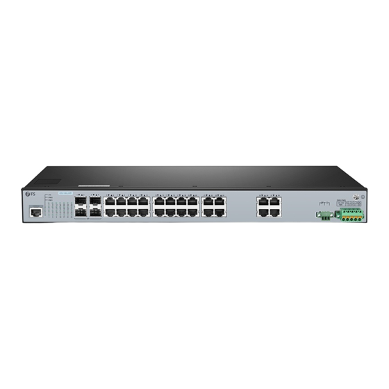
IES5100-24TF Switch
L3 MANAGED INDUSTRIAL SWITCH
L3 MANAGED INDUSTRIEllER SWITCH
SWITCH INDUSTRIEL MANAGEABLE L3
Quick Start Guide
Quick-Start Anleitung
Guide de Démarrage Rapide
6
7
8
9
10
11
12
13
14
15
16
17
18
19
20
21
22
23
24
V1.0
25
26
27
28
PW R1/ PW
R2
100 -24 0V
N L
L N
PW R
AC
DC
Publicité

Manuels Connexes pour FS IES5100-24TF


Sommaire des Matières pour FS IES5100-24TF
- Page 1 10 14 18 22 13 17 21 25 PW R1/ PW 100 -24 0V PW R IES5100-24TF Switch L3 MANAGED INDUSTRIAL SWITCH L3 MANAGED INDUSTRIEllER SWITCH SWITCH INDUSTRIEL MANAGEABLE L3 Quick Start Guide V1.0 Quick-Start Anleitung Guide de Démarrage Rapide...
- Page 2 Introduction Thank you for choosing IES5100-24TF Managed Switch. This guide is designed to familiarize you with the layout of the switch and describe how to deploy the switch in your network. IES5100-24TF PWR2 PWR1 PWR1/ PWR2 100-240V CONSOLE IES5100-24TF Accessories...
- Page 3 Ports Description RJ45 10/100/1000BASE-T ports for Ethernet connection IES5100-24TF SFP ports for 100M/1G connection CONSOLE A RJ45 console port for serial management PWR2 PWR1 Front Panel Grounding Piont CONSOLE IES5100-24TF PWR2 PWR1 PWR1/ PWR2 100-240V CONSOLE Power Alarm Output Terminal Block Connector...
- Page 4 Installation Requirements Before the installation, make sure that you have the following: Workstations running Windows XP/2003/Vista/7/8/10/2008, MAC OS X or later, Linux, UNIX, or other platforms that are compatible with TCP/IP protocols. Workstations installed with Ethernet NIC (Network Interface Card). Serial Port Connection (Terminal) The above Workstations come with COM Port (DB9) or USB-to-RS232 converter.
- Page 5 Mounting the Switch Desk Mounting IES510 0-24TF PWR2 PWR1 CONSOL E PWR1/ PWR2 100-240 V 1. Attach four rubber pads to the bottom. 2. Place the chassis on a desk. Rack Mounting PW R1 /P W 10 0- 24 0V PW R 1.
- Page 6 10 14 18 22 13 17 21 25 PW R1/ PW 100 -24 0V PW R IES5100-24TF PWR2 PWR1 CONSOLE 2. Attach the switch to the rack using the screws and tighten it. Grounding the Switch IES 51 00 -2...
- Page 7 Connecting the Power The Front Panel of the switch indicates an AC/DC inlet power socket and consists of one terminal block connector within 5 contacts. Please follow the steps below to insert the power wire. 1. Press the orange button with your hand or a flat-blade screwdriver. PWR1/ PWR2 100-240V PWR1/ PWR2...
- Page 8 2. Insert positive/negative AC/DC power wires into Contacts + and - for Power 1 and Power 2, then release the button. PWR1 PWR2 Positive (+) Pin Negative (-) Pin Pin 2 / 4 Pin 1 / 5 NOTE: The wire gauge for the terminal block should be in the range of 12-24 AWG. Connecting the RJ45 Ports IE S5 10 0- 24 SY S...
- Page 9 Connecting the SFP Ports IE S5 10 0- 24 SY S PW R2 PW R1 CO NS OL E 12 16 20 24 11 15 19 23 10 14 18 22 13 17 21 25 SF P 1. Plug the compatible SFP transceiver into the SFP port. 2.
- Page 10 Configuring the Switch Configuring the Switch Using the Web-based Interface Step 1: Connect the computer to any RJ45 port of the switch using the network cable. Step 2: Set the IP address of the computer to 192.168.1.x (“x” is any number from 2 to 255). Step 3: Open a web browser, enter the default IP address of the switch 192.168.1.1, and enter the default username and password, admin/admin.
- Page 11 Product Warranty FS ensures our customers that any damage or faulty items due to our workmanship, we will offer a free return within 30 days from the day you receive your goods. This excludes any custom-made items or tailored solutions.
- Page 12 Einführung Vielen Dank, dass Sie sich für den IES5100-24TF Managed Switch entschieden haben. Diese Anleitung soll Sie mit dem Aufbau des Switches vertraut machen und beschreibt, wie Sie den Switch in Ihrem Netzwerk einsetzen. IES5100-24TF PWR2 PWR1 PWR1/ PWR2 100-240V...
- Page 13 Ports Beschreibung RJ45 10/100/1000BASE-T-Ports für Ethernet-Verbindung SFP-Ports für 100M/1G-Verbindung IES5100-24TF CONSOLE Ein RJ45-Console-Port für die serielle Verwaltung PWR2 Vorderseite PWR1 Erdungspunkt IES5100-24TF PWR2 CONSOLE PWR1 PWR1/ PWR2 100-240V CONSOLE Stromalarmausgang Klemmenblock-Anschluss LEDs an der Vorderseite RJ45 IES5100-24TF PWR2 PWR1/ PWR2...
- Page 14 Installationsvoraussetzungen Bevor Sie mit der Installation beginnen, vergewissern Sie sich, dass Sie über die folgenden Dinge verfügen: Workstations mit Windows XP/2003/Vista/7/8/10/2008, MAC OS X oder höher, Linux, UNIX oder anderen Plattformen, die mit TCP/IP-Protokollen kompatibel sind. Workstations, die mit Ethernet-Netzwerkkarten installiert werden. Serielle Schnittstellenverbindung (Terminal) Die oben genannten Workstations werden mit COM-Port (DB9) oder USB-zu-RS232-Konverter geliefert.
- Page 15 Montage des Switches Montage auf einem Tisch IES510 0-24TF PWR2 PWR1 CONSOL E PWR1/ PWR2 100-240 V 1. Bringen Sie vier Gummipads an der Unterseite an. 2. Stellen Sie das Gehäuse auf den Tisch. Rack-Montage PW R1 /P W 10 0- 24 0V PW R 1.
- Page 16 10 14 18 22 13 17 21 25 PW R1/ PW 100 -24 0V PW R IES5100-24TF PWR2 PWR1 CONSOLE 2. Befestigen Sie den Switch mit vier M6-Schrauben und Käfigmuttern am Rack. Erdung des Switches IES 51 00 -2 4T F...
- Page 17 Anschließen der Stromversorgung Die Vorderseite des Switchs ist eine AC/DC-Eingangssteckdose und besteht aus einem Anschlussklemmenblock mit 5 Kontakten. Bitte befolgen Sie die nachstehenden Schritte, um das Stromkabel einzuführen. 1. Drücken Sie die orangefarbene Taste mit der Hand oder einem Schlitzschraubendreher. PWR1/ PWR2 100-240V PWR1/ PWR2...
- Page 18 2. Stecken Sie positive/negative AC/DC-Stromkabel in die Kontakte + und - für Power 1 und Power 2, lassen Sie dann die Taste los. PWR1 PWR2 Positive (+) Pin Negative (-) Pin Pin 2 / 4 Pin 1 / 5 HINWEIS: Die Drahtstärke für die Klemmleiste sollte im Bereich von 12 bis 14AWG liegen.
- Page 19 Anschließen der SFP-Ports IE S5 10 0- 24 SY S PW R2 PW R1 CO NS OL E 12 16 20 24 11 15 19 23 10 14 18 22 13 17 21 25 SF P 1. Stecken Sie den kompatiblen SFP-Transceiver in den SFP-Port. 2.
- Page 20 Konfiguration des Switches Konfigurieren des Switches über das webbasierte Interface Schritt 1: Schließen Sie den Computer über das Netzwerkkabel an einen beliebigen RJ45 Port des Switches an. Schritt 2: Stellen Sie die IP-Adresse des Computers auf 192.168.1.x ein. ("x" ist eine beliebige Zahl von 2 bis 255.).
- Page 21 Produktgarantie FS garantiert seinen Kunden, dass wir bei Schäden oder fehlerhaften Artikeln, die auf unsere Verarbeitung zurückzuführen sind, eine kostenlose Rückgabe innerhalb von 30 Tagen nach Erhalt der Ware anbieten. Dies gilt nicht für maßgefertigte Artikel oder maßgeschneiderte Lösungen.
- Page 22 Introduction Merci d'avoir choisi le Switch Manageable IES5100-24TF. Ce guide est conçu pour vous puissiez vous familiariser avec la configuration du switch et décrit comment procéder à son déploiement. IES5100-24TF PWR2 PWR1 PWR1/ PWR2 100-240V CONSOLE IES5100-24TF Accessoires Support de Montage x 2 Câble de Console x 1...
- Page 23 Ports Description RJ45 Ports 10/100/1000BASE-T pour la connexion Ethernet Ports SFP pour connexion 100M/1G IES5100-24TF CONSOLE Un port console RJ45 pour la gestion en série PWR2 Panneau Frontal PWR1 Point de Mise à la Terre IES5100-24TF PWR2 CONSOLE PWR1 PWR1/ PWR2...
- Page 24 Exigences d'Installation Avant l'installation, assurez-vous que vous disposez des éléments suivants : Postes de Travail fonctionnant avec Windows XP/2003/Vista/7/8/10/2008, MAC OS X ou une version ultérieure, Linux, UNIX, ou toute autre plateforme compatible avec les protocoles TCP/IP. Postes de Travail installées avec une Carte d'Interface Réseau (NIC) Ethernet. Connexion au Port Série (Terminal) Les Postes de Travail ci-dessus sont livrées avec un Port COM (DB9) ou un convertisseur USB vers RS232.
- Page 25 Installation du Switch Installation sur Support/Bureau IES510 0-24TF PWR2 PWR1 CONSOL E PWR1/ PWR2 100-240 V 1. Fixez quatre coussins en caoutchouc à la base. 2. Placez le châssis sur un support/bureau. Installation dans un Rack PW R1 /P W 10 0- 24 0V PW R 1.
- Page 26 18 22 13 17 21 25 PW R1/ PW 100 -24 0V PW R IES5100-24TF PWR2 PWR1 CONSOLE 2. Fixez le switch au rack à l'aide des vis et serrez-les. Mise à la Terre du Switch IES 51 00 -2...
- Page 27 Connexion de l'Alimentation Le Panneau Frontal du switch présente une prise d'alimentation AC/DC et se compose d'un connecteur de type bornier à 5 contacts. Veuillez suivre les étapes ci-dessous pour insérer les fils d'alimentation. 1. Appuyez sur le bouton orange avec votre main ou un tournevis à lame plate. PWR1/ PWR2 100-240V PWR1/ PWR2...
- Page 28 2. Insérez les fils d'alimentation AC/DC positifs/négatifs dans les Contacts + et - pour l'alimentation 1 et l'alimentation 2, puis relâchez le bouton. PWR1 PWR2 Broche Positive (+) Broche Négative (-) Broche 2/4 Broche 1/5 NOTE : Le calibre du fil pour le bornier doit être de 12 à 24 AWG. Connexion au Port RJ45 IE S5 10 0- 24 SY S...
- Page 29 Connexion au Port SFP IE S5 10 0- 24 SY S PW R2 PW R1 CO NS OL E 12 16 20 24 11 15 19 23 10 14 18 22 13 17 21 25 SF P 1. Branchez le module SFP compatible sur le port SFP. 2.
- Page 30 Configuration du Switch Configuration du Switch à l'Aide de l'Interface Web Étape 1 : Connectez l'ordinateur à n'importe quel port RJ45 du switch à l'aide du câble réseau. Étape 2 : Définissez l'adresse IP de l'ordinateur à 192.168.1.x ("x" est un nombre quelconque compris entre 2 et 255).
- Page 31 Garantie du Produit FS garantit à ses clients que tout article endommagé ou défectueux dû à sa fabrication pourra être retourné gratuitement dans un délai de 30 Jours à compter de la date de réception de la marchandise. Ceci exclut les articles faits sur mesure ou les solutions personnalisées.
- Page 32 Any changes or modifications not expressly approved by the grantee of this device could void the user's authority to operate the equipment. Responsible party (only for FCC matter) FS.COM Inc. 380 Centerpoint Blvd, New Castle, DE 19720, United States https://www.fs.com...
- Page 33 Die FS.COM GmbH erklärt hiermit, dass dieses Gerät mit der Richtlinie 2014/30/EU und 2014/35/EU konform ist. Eine Kopie der EU-Konformitätserklärung finden Sie unter www.fs.com/de/company/quality_control.html FS.COM GmbH déclare par la présente que cet appareil est conforme à la Directive 2014/30/UE et 2014/35/UE. Une copie de la Déclaration UE de Conformité est disponible sur https://www.fs.com/fr/company/quality_control.html FS.COM LIMITED...