Table des Matières
Publicité
Les langues disponibles
Les langues disponibles
Publicité
Chapitres
Table des Matières

Manuels Connexes pour TOSOT TW09HQ1B2DI


Sommaire des Matières pour TOSOT TW09HQ1B2DI
- Page 1 FABRIQUÉ EN CHINE MANU EL DU P ROP RIÉTAI RE...
- Page 3 TW09HQ1B2DI TW09CQ1B2DI TW12HQ1B2DI TW12CQ1B2DI TW18HQ1B2DI TW18CQ1B2DI TW24HQ1B2DI TW24CQ1B2DI...
-
Page 4: Table Des Matières
Contenu Avis de fonctionnement Consignes de sécurité ..................1 Nom des pièces ....................6 Guide d'utilisation de l'écran Boutons de télécommande ................7 Introduction pour les icônes de l'écran d'affichage ..........7 Introduction pour les boutons de télécommande ..........8 Introduction des fonctions de combinaisons de boutons ........ -
Page 5: Consignes De Sécurité
Consignes de sécurité AVERTISSEMENT Fonctionnement et entretien Cet appareil n'est pas destiné à être utilisé par des personnes (notamment des enfants) ayant des capacités physiques, sensorielles ou intellectuelles réduites, ou par des personnes manquant d'expérience ou de connaissances, à moins qu'ils ne soient surveillés ou instruits quant à... - Page 6 Consignes de sécurité AVERTISSEMENT La maintenance doit être effectuée par du personnel qualifié. Sinon, elle peut provoquer des blessures corporelles ou des dommages matériels. Ne pas réparer le climatiseur par vous-même. Il pourrait provoquer des chocs électriques ou des dommages. Veuillez contacter le commerçant lorsque vous avez besoin de réparer le climatiseur.
- Page 7 Consignes de sécurité AVERTISSEMENT Branchement L'installation doit être effectuée par du personnel qualifié. Sinon, elle peut provoquer des blessures corporelles ou des dommages matériels. Vous devez suivre les règles de sécurité électrique lors de l'installation de l'unité. Selon la réglementation locale, utilisez un circuit d'alimentation qualifié...
- Page 8 Consignes de sécurité AVERTISSEMENT Ne mettez pas l'alimentation sous tension avant de terminer l'installation. Si le cordon d'alimentation est endommagé, il doit être remplacé par le fabricant, son agent de service ou un technicien qualifié afin d'éviter tout accident. La température du circuit de fluide réfrigérant sera élevée.
- Page 9 Précautions ATTENTION Pour l'air conditionné avec prise, la fiche doit être accessible après avoir terminé l'installation. Pour l'air conditionné sans fiche, le disjoncteur doit être installé dans la ligne. Si vous avez besoin de déplacer le climatiseur à un autre endroit, seule la personne qualifiée peut effectuer le travail.
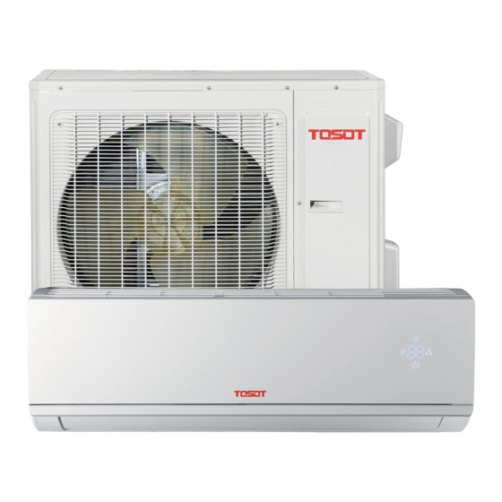
- Page 10 Noms des Pièces Unité intérieure entrée d'air panneau filtre bouton aux. Volet horizontale sortie d'air télécommande (Le contenu affiché ou la position du produit peuvent être différents des graphiques ci-dessus, s'il vous plaît se référer aux produits réels) Unité extérieure entrée d'air fil de connection sortie d'air...
- Page 11 Noms des Pièces Affichage Pour certains modèles: Pour certains modèles: Indicateur de fenêtre de Indicateur de Indicateur temp. indicateur de refroidissement reception de demarrage chauffage affichage indicateur de refroidissement fenêtre indicateur de Indicateur de Indicateur Indicateur reception Affichage demarrage chauffage de temp.
-
Page 12: Boutons De Télécommande
Boutons sur télécommande Bouton ON/OFF Bouton MODE Bouton FAN Bouton SWING Bouton TURBO MODE ▲/ button SWING TURBO Bouton SLEEP TEMP SLEEP Bouton TEMP WiFi CLOCK LIGHT Bouton WI FI TIMER TIMER Bouton LIGHT Bouton CLOCK Bouton TIMER ON / TIMER OFF Introduction des icônes sur l’écran d’affichage Je ressens... - Page 13 Introduction des boutons de la télécommande Note: ● Après l'avoir démarré, le climatiseur va faire un son. Indicateur de fonctionnement est ON (l'indicateur rouge). Vous pourrez ensuite utiliser le climatiseur à l’aide de la télécommande. ● Toujours en statut ON, en appuyant sur le bouton sur la télécommande, l’icône de signal sur l’écran de la télécommande clignote une fois et l'air conditionaire donnera un son «...
- Page 14 Introduction des boutons de la télécommande "▲" ou " ▼" pour régler la température. Appuyez sur "FAN" pour régler la vitesse du ventilateur. Appuyez sur "SWING" pour régler l'angle du souffle du ventilateur. (les unités refroidissement seulement ne vont pas recevoir le signal du mode chauffage. Si vous essayez de mettre l'unité en mode chauffage avec la télécommande, appuyez sur bouton ON/OFF ne démarrera pas l’unité).
- Page 15 Introduction des boutons de la télécommande Bouton TURBO Si vous appuyez sur cette touche alors que l'appareil fonctionne dans le mode COOL ou HEAT, le climatiseur va réfrigérer au maximum ou chauffer au maximum. L'icon " " sera affiché sur la telecommande. Appuyer sur ce meme bouton pour sortir de la fonction TURBO.
- Page 16 Introduction des boutons de la télécommande ● Par défaut, la température prédéfinie est afficher lorsque vous allumez l'appareil. Il n'y a pas d'affichage sur la télécommande. ● Uniquement pour les modèles dont l'unité intérieure a un affichage dual-8. ● Lors de la sélection de l'affichage de la température ambiante intérieure ou extérieure, l'indicateur intérieure de la température affiche la température correspondante et change automatiquement pour afficher la température prédéfinie, au bout de trois ou cinq secondes.
- Page 17 Introduction des boutons de la télécommande appui sur le bouton "▲" ou "▼" les ajustements du TIMER ON vont augmenter ou diminuer d'une minute. Appuyez sur le bouton "▲" ou " ▼ " pour plus de 2 secondes, le temps va changer rapidement jusqu'à...
- Page 18 Introduction de fonction pour les boutons de combinaison 8℃ Fonction Chauffage En mode chauffage, appuyez sur "TEMP" et "CLOCK" simultanément pour démarrer ou éteindre 8 ℃ fonction. Lorsque cette fonction est démarré, " " et "8 ℃" seront affichés sur la télécommande et le climatiseur gardera l'état de chauffage à 8 ℃. Appuyez sur "TEMP "et "...
- Page 19 Guide d'Utilisation Après avoir alimenter votre unité, appuyez sur "ON / OFF" sur la télécommande pour activer l'air conditionné. Appuyez sur "MODE" pour sélectionner le mode souhaité: AUTO, COOL, DRY, FAN, HEAT. Appuyez sur "▲" et " ▼" pour régler la température desirée.(La température ne peut etre ajustée sous le mode AUTO).
-
Page 20: Fonctionnement D'urgence
Fonctionnement d'urgence Si la télécommande est perdue ou endommagée, veuillez utiliser le bouton auxiliaire pour allumer ou éteindre le climatiseur. Voir les détails de l'opération: tel que montré dans la figure ci-dessous, ouvrir le panneau, appuyer sur le bouton auxiliaire pour allumer ou éteindre le climatiseur. Lorsque le climatiseur est allumé, il fonctionnera en mode AUTO. - Page 21 Nettoyage et entretien Nettoyage du filtre Nettoyer le filtre Ouvrir le panneau ● Utiliser un « attrape-poussière » ou Retirer le panneau d'un certain de l'eau pour nettoyer le filtre. angle tel que montré ci-dessous. ● Lorsque le filtre est très sale, utiliser de l'eau (en dessous de 45℃...
- Page 22 Nettoyage et entretien REMARQUE : À vérifier avant la saison d'utilisation Vérifier si les entrées/sorties d'air sont obstruées. 2.Vérifier si le disjoncteur, la fiche mâle et la fiche femelle sont en bon état. 3.Vérifier si le filtre est propre. 4.Vérifier si le support de montage pour l'unité extérieure est endommagée ou corrodée.
-
Page 23: Analyse Du Mauvais Fonctionnement
Analyse en cas de mauvais fonctionnement Analyse des phénomènes communs Veuillez vérifier les items plus bas avant de demander la maintenance. Si le mauvais fonctionnement ne peut être éliminé, veuillez contacter votre commerçant local ou du personnel qualifié. Phénomène À vérifier Solution ●... - Page 24 Analyse en cas de mauvais fonctionnement Phénomène À vérifier Solution ● Panne de courant? ● Attendre que le courant revienne. ● ● Fiche d'alimentation déserrée? Réinsérer la fiche ● Demander à un professionnel de ● Le disjoncteur se déclanche changer le disjoncteur ou la fréquemment ou la fusible est brûlée? fusible.
- Page 25 Analyse en cas de mauvais fonctionnement Phénomène À vérifier Solution ● Éliminer la source d'odeur. Émission ● Il y a peut-être une source d'odeur d'odeurs tel du mobilier, cigarette, etc... ● Nettoyer le filtre. Le climatiseur ● Débrancher l'alimentation, fonctionne ●...
- Page 26 Analyse en cas de mauvais fonctionnement d'erreur Code ● Lorsque le statut du climatiseur est anormal, l'indicateur de température de l'unité intérieure clignotera pour afficher le code d'erreur correspondant. Veuillez vous référer à la liste ci-dessous pour identifier le code d'erreur. Diagramme de l'indicateur ci-contre pour référence seulement.
- Page 27 Shéma des dimensions d'installation Distance du mur Au moins15cm Au moins 15cm Distance du mur Tuyau de drainage...
-
Page 28: Outils Pour L'installation
Outils pour l'installation 1 Indicateur de niveau 2 Tournevis 3 Perçeuse à percussion 4 Tête de forage 5 Évaseur 6 Clé dynamométrique 7 Clé à fourche 8 Coupe-tube 9 Détecteur de fuite 10 Pompe à vide 12 Multimètre Indicateur de pression 13 Clé... -
Page 29: Exigences Pour Le Branchement Électrique
Exigences pour le branchement électrique Consignes de sécurité 1.Doit suivre les règles de sécurité électrique lors de l'installation de l'unité. 2.Selon les régles de sécurité locale, utilisez un disjoncteur et une alimentation qualifiée. 3.Assurez-vous que l'alimentation est conforme aux exigences du climatiseur. Alimentation instable ou mauvais branchement ou mauvais fonctionnement. -
Page 30: Installation De L'unité Intérieure
Installation de l'unité intérieure Étape 1 : choix de l'emplacement pour l'installation Recommandez un emplacement pour l'installation au client et ensuite confirmez avec lui. Étape 2: Installer le support de montage au mur 1. Accrocher le support de montage au mur; le régler en position horizontale avec l'indicateur de niveau et ensuite aligner les trous sur le mur. - Page 31 Installation de l'unité intérieure Intérieur Extérieur Note: ● Prêter attention à la poussière et prendre des mesures de sécurité pertinentes lors de l'ouverture du trou. ● Les particules d'extension en plastique 5-10 ne sont pas fournis et doivent être achetés localement. Étape 4: tuyau de sortie 1.
- Page 32 Installation de l'unité intérieure Couple de serrage (N . m) Diamètre écrou clé plate Φ 6 15~20 Φ 9.52 30~40 écrou de raccordement Φ 12 45~55 tuyau Φ 16 60~65 clé dynamométrique Φ 19 70~75 tuyau intérieur 4. Envelopper le tuyau intérieur et le joint de connexion du tuyau avec du tuyau d'isolation, puis l'entourer de ruban tuyau d'isolation...
- Page 33 Installation de l'unité intérieure 2. Faites passer le fil de branchement électrique par le trou du câble trou pour le câcle transversal à l'arrière de l'unité intérieure, puis tirez-la hors de la face avant. fil de branchement 3. Retirer la pince du fil; brancher le fil de branchement au terminal de branchement selon les couleurs, serrer les vis et fixer le fil de branchement avec la pince du fil.
- Page 34 Installation de l'unité intérieure Étape 8: attacher les tuyaux Attacher le tuyau de connexion, le cordon tuyau de branchement tuyau de drainage bande d'alimentation et le tuyau de drainage avec la bande câble d'alimentation int. et ext. unité intérieure tuyau de gaz alimentation intérieure tuyau de liquide...
-
Page 35: Installation De L'unité Extérieure
Installation de l'unité extérieure Étape 1: installer le support de l'unité extérieure (le choisir selon la véritable situation d'installation) Choisir l'emplacement d'installation selon la structure de la maison. Installer le support de l'unité extérieure sur l'emplacement choisi avec les vis d'expansion. Note: ●... - Page 36 Installation de l'unité extérieure Étape 4: brancher les tuyaux intérieurs et extérieurs 3. Pré-serrer l'écrou de raccordement à la main. Retirer la vis de la poignée droite de l'unité extérieure et retirer la poignée. joint de tuyau écrou de raccordement poignée Retirer la vis du couvercle de la valve et Serrer l'écrou de raccordement avec la clé...
- Page 37 Installation de l'unité extérieure Fixer le fil de connexion de l'alimentation et le fil de commande de signal avec le clip de câble (uniquement pour l'unité de refroidissement et l'unité de chauffage) Note: ● Après avoir serré les vis, tirer légèrement sur le câble d'alimentation pour vérifier s'il est fermement attaché...
-
Page 38: Pompe À Vide
Pompe à vide Utiliser une pompe à vide Enlever les embouts de soupape sur la soupape de liquide et la valve de liquide piézomètre soupape de gaz et l'écrou de réfrigérant de l'évent de valve de gaz chargement. évent de chargement Branchez le tuyau de chargement bouchon de valve de réfrigérant... -
Page 39: Essai De Fonctionnement
À vérifier après l'installation ● Vérifier selon les exigences après avoir terminé l'installation. Éléments à vérifier Mauvais fonctionnement possible L'unité peut tomber, vibrer ou faire du bruit. L'unité a-t-elle été installée fermement ? Avez-vous fait le test de fuite de réfrigérant ? Pourrait causer une capacité... - Page 40 Configuration du tuyau de connexion 1. Longueur standard de tuyau de connexion ● 5m, 7.5m, 8m. 2. Longueur min. de tuyau de connexion est 3 m. 3. Longueur max. de tuyau de connexion et différence de hauteur max. Longueur max. Longueur max Capacité...
-
Page 41: Configuration De Tuyau De Connexion
Configuration du tuyau de connexion Quantité de charge de gaz réfrigérant supplémentaire pour R22, R407C et R410A et R134a Diamètre du tuyau de connexion Accélérateur de l'unité extérieure Refroidissement Refroidissement et chauffage(g/m) Tuyau de liquide(mm) Tuyau de gaz (mm) seulement (g/m) Φ6 Φ9.52 or Φ12 Φ6 or Φ9.52... -
Page 42: Méthode D'expansion De Tuyau
Méthode d'extension de tuyau Note: L'extension inappropriée d'un tuyau est la principale cause de fuite de réfrigérant. Veuillez extentionner le tuyau selon les étapes suivantes : Élargir le port Couper le tuyau ● Confirmer la longueur de tuyau selon la ●... - Page 43 MADE IN CHINA OWNER’S MANUAL...
- Page 45 TW09HQ1B2DI TW09CQ1B2DI TW12HQ1B2DI TW12CQ1B2DI TW18HQ1B2DI TW18CQ1B2DI TW24HQ1B2DI TW24CQ1B2DI...
- Page 46 Content Operation Notices Precautions......................1 Parts name ......................9 Screen Operation Guide Buttons on remote controller ................11 Introduction for icons on display screen .............. 11 Introduction for buttons on remote controller ............12 Function introduction for combination buttons ............. 16 Operation guide ....................
- Page 47 Explanation of Symbols Indicates a hazardous situation that, if not avoided, will DANGER result in death or serious injury. Indicates a hazardous situation that, if not avoided, could WARNING result in death or serious injury. Indicates a hazardous situation that, if not avoided, may CAUTION result in minor or moderate injury.
-
Page 48: Precautions
Precautions WARNING Operation and Maintenance This appliance can be used by children aged from 8 years and above and persons with reduced physical, sensory or mental capabilities or lack of experience and knowledge if they have been given supervision or instruction concerning use of the appliance in a safe way and understand the hazards involved. - Page 49 Precautions WARNING Maintenance must be performed by qualified professionals. Otherwise, it may cause personal injury or damage. Do not repair air conditioner by yourself. It may cause electric shock or damage. Please contact dealer when you need to repair air conditioner. Do not extend fingers or objects into air inlet or air outlet.
- Page 50 Precautions WARNING Attachment Installation must be performed by qualified professionals. Otherwise, it may cause personal injury or damage. Must follow the electric safety regulations when installing the unit. According to the local safety regulations, use qualified power supply circuit and circuit break. Do install the circuit break.
- Page 51 Precautions WARNING Do not put through the power before finishing installation. If the supply cord is damaged, it must be replaced by the manufacturer, its service agent or similarly qualified persons in order to avoid a hazard. The temperature of refrigerant circuit will be high, please keep the interconnection cable away from the copper tube.
- Page 52 Precautions WARNING For the air conditioner with plug, the plug should be reachable after finishing installation. For the air conditioner without plug, an circuit break must be installed in the line. If you need to relocate the air conditioner to another place, only the qualified person can perform the work.
- Page 53 Precautions FCC STATEMENT (1) this device may not cause harmful interference, and (2) this device must accept any interference received,including interference that may cause undesired operation. NOTE: This equipment has been tested and found to comply with the limits for a Class B digital device, pursuant to part 15 of the FCC Rules.
- Page 54 Precautions IC STATEMENT This device complies with Industry Canada licence- exempt RSS standard(s). Operation is subject to the following two conditions: (1) this device may not cause interference, and (2) this device must accept any interference, including interference that may cause undesired operation of the device.
- Page 55 Precautions IC STATEMENT antennes utilisées pour cet émetteur doivent être installées et doivent fonctionner à au moins 20 cm de distance des utilisateurs et ne doivent pas être placées près d’autres antennes ou émetteurs ou fonctionner avec ceux-ci. Les installateurs doivent s’assurer qu’une distance de 20 cm sépare l’appareil (à...
-
Page 56: Parts Name
Parts name Indoor Unit air inlet panel aux.button horizontal louver air outlet MODE SWING TURBO SLEEP TEMP WiFi CLOCK LIGHT TIMER TIMER (Display content or position may be different from above graphics, please refer to actual products) remote NOTICE: Actual product may be different from above graphics, please refer to actual products. - Page 57 Parts name Display For some models: temp. For some models: indicator heating cooling power receiver indicator indicator indicator window display cooling indicator receiver power window indicator heating temp. drying display drying indicator indicator indicator indicator For some models: For some models: drying indicator heating...
-
Page 58: Buttons On Remote Controller
Buttons on remote controller ON/OFF button MODE button FAN button SWING button TURBO button MODE ▲/ button SWING TURBO SLEEP button TEMP SLEEP TEMP button WiFi CLOCK LIGHT WiFi button TIMER TIMER LIGHT button CLOCK button TIMER ON / TIMER OFF button Introduction for icons on display screen Set fan speed... -
Page 59: Introduction For Buttons On Remote Controller
Introduction for buttons on remote controller Note: ● This is a general use remote controller, it could be used for the air conditioners with multifunction; For some function, which the model doesn't have, if press the corresponding button on the remote controller that the unit will keep the original running status. - Page 60 Introduction for buttons on remote controller ● When selecting fan mode, the air conditioner will only blow fan, no cooling and no heating. Press "FAN" button to adjust fan speed. Press "SWING" button to adjust fan blowing angle. ● When selecting heating mode, the air conditioner operates under heat mode. Heat indicator on indoor unit is ON(This indicator is not available for some models).
- Page 61 Introduction for buttons on remote controller ● When selecting " ", air conditioner is blowing fan automatically. Horizontal louver will automatically swing up & down at maximum angle. ● When selecting " 、 、 、 、 ● When selecting " 、...
- Page 62 Introduction for buttons on remote controller ● When selecting " " or no display with remote controller, temperature indicator on indoor unit displays set temperature. ● When selecting " " with remote controller, temperature indicator on indoor unit displays indoor ambient temperature. ●...
-
Page 63: Function Introduction For Combination Buttons
Introduction for buttons on remote controller ● TIMER ON button "TIMER ON" button can set the time for timer on. After pressing this button, " " icon disappears and the word "ON" on remote controller blinks. Press "▲" or " "button to adjust TIMER ON setting. - Page 64 Function introduction for combination buttons Auto clean function Under unit off status, hold "MODE" and "FAN" buttons simultaneously for 5s to turn on or turn off the internal clean function. When the internal clean function is turned on, indoor unit displays “CL”. (This function is applicable for some models) During the self-cleaning process of evaporator, the unit will perform fast cooling or fast heating.
-
Page 65: Operation Guide
Function introduction for combination buttons will automatically adjust the indoor temperature according to the detected tempera- ture. Press this two buttons simultaneously again to close I FEEL function and " " will disappear. ● Please put the remote controller near user when this function is set. Do not put the remote controller near the object of high temperature o r low temperature in order to avoid detecting inaccurate ambient temperature.When I FEEL function is turned on, the remote controller should be put within the area where indoor... -
Page 66: Emergency Operation
Emergency operation l l o turn off the air conditioner. The operation in details is as below: air conditioner. When the air conditioner is turned on, it will operate under auto mode. panel aux. button WARNING: Use insulated object to press the auto button Clean and maintenance WARNING ■... - Page 67 Clean and maintenance Open panel Pull out the panel to a certain ● Use dust catcher or water to the water (below 45℃ (113°F)) to clean it, and then put it in a shady and cool place to dry. panel cover tightly. WARNING operation environment, clean frequency can be increased.
- Page 68 Clean and maintenance NOTICE: Checking before use-season 1. Check whether air inlets and air outlets are blocked. 2. Check whether circuit break, plug and socket are in good condition. 4. Check whether drainage pipe is damaged. NOTICE: Checking after use-season 1.
-
Page 69: Malfunction Analysis
Malfunction analysis General phenomenon analysis Please check below items before asking for maintenance. If the malfunction still can’t be eliminated, please contact local dealer or qualified professionals Phenomenon Check items Solution ● Whether it's interfered severely ● Pull out the plug. Reinsert (such as static electricity, stable the plug after about 3min, and voltage)? - Page 70 Malfunction analysis Phenomenon Check items Solution ● Power failure? ● Wait until power recovery. ● Is plug loose? ● Reinsert the plug. ● Air switch trips off or ● Ask professional to replace fuse is burnt out? circuit break or fuse. Air condit- ●...
- Page 71 Malfunction analysis Phenomenon Check items Solution ● Whether there’s odour source, ● Eliminate the odour source. Odours are such as furniture and cigarette, emitted ● Clean the filte . etc. ● Whether there’s interference, ● Disconnect power, put back Air conditioner such as thunder, wireless power, and then turn on the operates nor-...
- Page 72 Malfunction analysis Error Code ● When air conditioner status is abnormal, temperature indicator on indoor unit will ation of error code. Error code Troubleshooting It can be eliminated after restarting the unit. If not, please It can be eliminated after restarting the unit. If not, please It can be eliminated after restarting the unit.
-
Page 73: Installation Dimension Diagram
Installation dimension diagram Space to the wall At least 15cm At least 15cm Space to the wall... -
Page 74: Safety Precautions For Installing And Relocating The Unit
Safety precautions for installing and relocating the unit To ensure safety, please be mindful of the following precautions. Warning When installing or relocating the unit, be sure to keep the refrigerant circuit free from air or substances other than the specified refrigerant. Any presence of air or other foreign substance in the refrigerant circuit will cause system pressure rise or compressor rupture, resulting in injury. -
Page 75: Tools For Installation
Tools for installation 1 Level meter 2 Screw driver 3 Impact drill 4 Drill head 5 Pipe expander 6 Torque wrench 7 Open-end wrench 8 Pipe cutter 9 Leakage detector 10 Vacuum pump 11 Pressure meter 12 Universal meter 13 Inner hexagon spanner 14 Measuring tape Note: ●... -
Page 76: Requirements For Electric Connection
Requirements for electric connection Safety precaution 1. Must follow the electric safety regulations when installing the unit. air switch. 3. Make sure the power supply matches with the requirement of air conditioner. Unstable power supply or incorrect wiring or malfunction. Please install proper power supply cables before using the air conditioner. -
Page 77: Installation Of Indoor Unit
Installation of indoor unit Step one: choosing installation location rm it with the client. Step two: install wall-mounting frame Hang the wall-mounting frame on the wall; adjust it in horizontal position with the plastic expansion particles in the holes. 3. Fix the wall-mounting frame on the wall with tapping screws and then check if the frame is firmly installed by pulling the frame.If the plastic expansion particle is loose, please drill another fixing hole nearby. - Page 78 Installation of indoor unit Indoor outdoor Note: ● Pay attention to dust prevention and take relevant safety measures when Φ55/ opening the hole. 5-10 Φ70 Step four: outlet pipe 1. The pipe can be led out in the When select leading out the pipe direction of right, rear right, left or from left or right, please cut off the rear left.
- Page 79 Installation of indoor unit Hex nut diameter Tightening torque (N . m) open-end wrench Φ 6 15~20 Φ 9.52 30~40 union nut Φ 12 45~55 pipe Φ 16 60~65 torque wrench Φ 19 70~75 indoor pipe 4. Wrap the indoor pipe and joint of con- nection pipe with insulating pipe, and then wrap it with tape.
- Page 80 Installation of indoor unit 2. Make the power connection wire go cable-cross through the cable-cross hole at the back hole of indoor unit and then pull it out from the front side. power connection wire 3. Remove the wire clip; connect the power connection wire to the wiring terminal according to the color;...
- Page 81 Installation of indoor unit Step eight: bind up pipe 1. Bind up the connection pipe, power drain hose connection pipe band cord and drain hose with the band. indoor and outdoor power cord indoor unit pipe indoor power cord liquid pipe 3.
-
Page 82: Check After Installation
Check after installation ● Check according to the following requirement after finishing installation. Items to be checked Possible malfunction Has the unit been installed firmly? The unit may drop, shake or emit noise. Have you done the refrigerant leakage It may cause insufficient cooling test? (heating) capacity. - Page 83 Configuration of connection pipe 1. Standard length of connection pipe ● 5m, 7.5m, 8m. 2. Min. length of connection pipe is 3m. 3. Max. length of connection pipe. Max. length of connection pipe Unit: m Max. length Max. length Cooling Cooling of connec- of connec-...
- Page 84 Configuration of connection pip Additional refrigerant charging amount for R22, R407C, R410A and R134a Diameter of connection pipe Outdoor unit throttle Liquid pipe(mm) Gas pipe(mm) Cooling only(g/m) Cooling and heating(g/m) Φ6 Φ9.52 or Φ12 Φ6 or Φ9.52 Φ16 or Φ19 Φ12 Φ19 or Φ22.2 Φ16...
-
Page 85: Pipe Expanding Method
Pipe expanding method Note: Improper pipe expanding is the main cause of refrigerant leakage. Please expand the pipe according to the following steps: A: Cut the pipe E: Expand the port ● Confirm the pipe length according t ● Expand the port with expander. the distance of indoor unit and hard outdoor unit.