
Manuels Connexes pour Megger DLRO-10


Sommaire des Matières pour Megger DLRO-10
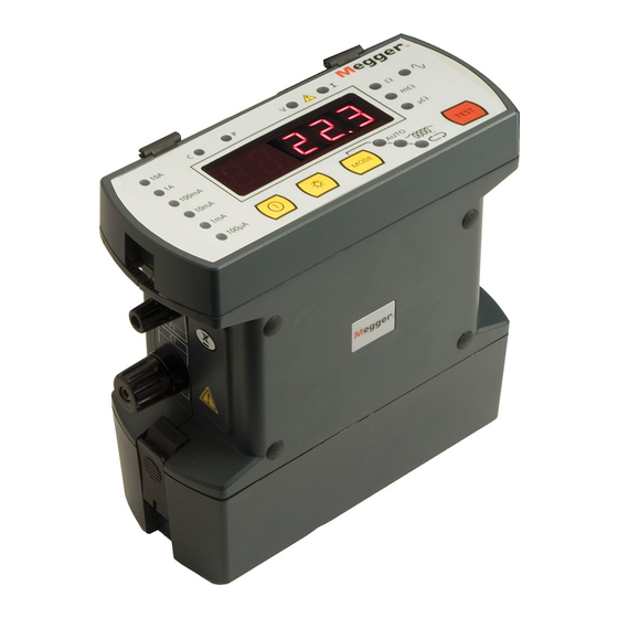
- Page 1 DLRO -10 & DLRO -10X ® ® Digital Low Resistance Ohmmeter USER GUIDE GUIDE DE L’UTILISATEUR BEDIENUNGSANLEITUNG GUIDA PER L’UTENTE GUIA DEL USUARIO...
- Page 2 If it is impossible to de-energise the circuit, (e.g. high voltage batteries cannot be switched off while their connections are tested) the user must be aware of the dangers. The instrument terminals will become live when connected to the circuit. Therefore when used on hazardous voltages custom Megger DH6 test leads must be used. Testing inductive circuits can be hazardous: After testing an inductive load there will be an amount of energy stored in the inductance.
-
Page 3: Table Des Matières
CONTENTS Safety Warnings Continuous Mode General Description High Power Mode General Operation - DLRO 10 Unidirectional Mode Test Current Indicators Test Techniques & Applications Noise Lamp Testing Using DH4 Duplex Handspikes ‘C’ & ‘P’ Indicators Testing Using Handspikes Or Individual Leads. ‘V’... -
Page 4: General Description
GENERAL DESCRIPTION The DUCTER DLRO 10 and DUCTER DLRO 10X make up a family of low resistance ohmmeters that measure resistances in the range from 0.1 µΩ to 2 kΩ. Both instruments provide a maximum test current of 10 Amps d.c. which is automatically selected according to the value of resistance being tested. The DLRO 10X allows you to override this automatic selection and select your own test current. -
Page 5: General Operation - Dlro 10
GENERAL OPERATION - DLRO 10 ‘C’ & ‘P’ Indicators The ‘C’ lamp illuminates to indicate contact failure in the ‘C1-C2’ loop. The ‘P’ lamp illuminates when there is a break in the P1-P2 loop. ‘V’ & ‘I’ Warning Indicators If external voltage is applied to the terminals the ‘V’ lamp will flash. This is a warning that the item under test is live and might be dangerous. -
Page 6: General Operation - Dlro 10X
GENERAL OPERATION - DLRO 10X charge remaining, index number of the next test, number of tests already stored and the current date and time. This screen also provides access to the menuing system, through which you set up your instrument and choose the desired test parameters. Navigation of this menuing system is by means of the cursor control and Enter key. -
Page 7: External Voltage Warning
GENERAL OPERATION - DLRO 10X Options Menu inadequate. Check the contacts, since a measurement cannot be made if any of these messages is visible on the display. The Options menu has five options that are not related to each other, as shown below. -
Page 8: Download
GENERAL OPERATION - DLRO 10X Download Passbands causes the entire contents of the data store to be output This option allows you to set upper and lower limits between which the to the RS232 port to the left of the display. A copy of test result average must fall if it is to be signalled as a Pass (a long tone AVO Download Manager, which facilitates downloading from the buzzer). -
Page 9: Delete Data
GENERAL OPERATION - DLRO 10X The row below DD MM YY HH MM contains respectively the date, the the bottom of the screen and press Enter. month, the two-digit year, the hour of the day in 24-hour notation and the With the exception of tests carried out in Continuous mode, at the end of minute. -
Page 10: Test Result Storage
GENERAL OPERATION DLRO 10X If you wish to add comments to the test results, instead of pressing Enter, briefly press one of the twelve keys on the keypad. You will enter a memo screen that allows you to enter up to 200 characters of alphanumeric information concerning the test. - Page 11 GENERAL OPERATION DLRO 10X Decimal point or full stop Ohms symbol Ω lower case m (abbreviation for milli) µ Symbol for micro Symbol known as hash or pound and commonly used as shorthand for “number” Percent sign Left round bracket Right round bracket Hyphen, dash or minus sign Slash...
-
Page 12: Test Modes
TEST MODES TEST MODES Continuous mode DLRO 10 has 4 test modes which are selected by repeated presses of the Continuous mode requires the connections to be made before pressing Mode button. At the end of each test, DLRO 10 will display the average of the Test button. -
Page 13: Unidirectional Mode
Test Modes The time required for a stable reading may vary from a few seconds up to several minutes depending on the inductance and resistance of the test sample. There is no time limit for the inductive mode test, which will continue until the operator presses the Test button. -
Page 14: Test Techniques & Applications
Since your DLRO always ensures good contact before applying the full Note: When used on hazardous voltages Megger DH6 test leads must be test current, there will be no ‘splash’ to erode the contact tips. However, should the tips become worn or blunted, they can be simply replaced by used. -
Page 15: Test Sequence
TEST TECHNIQUES & APPLICATIONS TEST SEQUENCE leads and 30 W within your instrument. If the ambient temperature is high this will cause internal overheating and the message “hot” will appear on Pressing the TEST button starts the test sequence. the instrument display and testing will be halted. Contact resistance is checked by passing 100 µA through the C1-C2 loop After a few minutes to cool down, testing will be allowed to continue. -
Page 16: Battery Module And Care
BATTERY MODULE AND CARE THE BATTERY MODULE To charge the battery, your battery module must be removed from the The battery module contains nickel-metal-hydride cells and has a built- instrument. Remove the module by pressing on the raised circular area of the retaining clips and pull the top of the clip away from the instrument in battery-management system that controls charging and monitors body. -
Page 17: The Battery State Indicator
BATTERY MODULE AND CARE Please note that all batteries suffer a reduced life if exposed to Not charging. There is a temperature problem. constant high temperatures. A constant temperature of 30°C will The battery is too hot or too cold and Flashing probably cause the battery to fail in less than 5 years. - Page 18 BATTERY MODULE AND CARE WARNING Connecting to greater than 15 volts can cause permanent damage to the battery module. The DLRO10 and DLRO10X can also be powered from a mains / line power supply unit the DLRO10LPU. This is available as an accessory, details can be found in the Accessories section of this user guide...
-
Page 19: Specifications
SPECIFICATIONS Ranges Full Scale Resolution Accuracy Full Scale Volts Test Current Resistance Induction Resistance Induction 1,9999 mΩ 0,1 µΩ ±0,2%±0,2 µΩ 20 mV 10 A 19,999 mΩ 1 µΩ ±0,2%±2 µΩ 20 mV 20 mV 199,99 mΩ 10 µΩ ±0,2%±20 µΩ 20 mV 200 mV 100 mA... - Page 20 Safety In accordance with IEC61010-1 600 V Category III - only when DH6 leads are used In accordance with IEC61326-1 Operation inaccuracies Refer to www.megger.com Dimensions 220 x 100 x 237 mm (8.6 x 4 x 9.5 in) Weight 2.6 kg (5 3/4 lb.) including battery module...
-
Page 21: Troubleshooting
TROUBLE SHOOTING Error Message Fault Action required. bAtt The main battery module is low. Recharge the main battery or replace with a charged one _ _ _ _ _ An error has occurred during the measurement. Rectify the error and repeat the measurement. e.g. -
Page 22: Accessories
ACCESSORIES Standard Accessories supplied with instrument. The DLRO10X is seen here fitted with the optional DLRO10LPU 7 Ah NiMH battery module. 6340-101 Ideal for repetitive testing applications such as DH4 Duplex handspikes (2), one with indicator lights. manufacturing production line use 1.2m / 4 ft 6111-503 Battery charger for operation from 115/230 V. -
Page 23: Repair And Warranty
Approved Repair Companies A number of independent instrument repair companies have been approved for repair work on most Megger instruments, using genuine Megger spare parts. Consult the Appointed Distributor / Agent regarding spare parts, repair facilities and advice on the best course of action to take. -
Page 24: End Of Life Disposal
WEEE sent freight pre-paid to the appropriate address. A copy of the Invoice and The crossed out wheeled bin placed on the Megger products is a reminder of the packing note should be sent simultaneously by airmail to expedite not to dispose of the product at the end of it’s product life with general clearance through Customs. -
Page 25: Ohmmêtre Digital Basse Rèsistance
DLRO -10 & DLRO -10X ® ® Ohmmêtre digital basse rèsistance GUIDE DE L’UTILISATEUR... - Page 26 OPERATION Avertissements de sécurité Stockage Batterie presque épuisée Menu Gamme Erreur : Réinitialisation Description générale Problème de surtension Saisie de notes dans l’écran mémo Fonctionnement général - DLRO 10 Stockage des résultats des tests Caractéristiques techniques 43-44 Indicateurs d’intensité de test 29 Fonctionnement du clavier Témoin de bruit Dépannage...
-
Page 27: Avertissements De Sécurité
être averti du danger. Les pointes de touche de l’instrument seront sous tension lorsqu’elles seront connectées au circuit. C’est pourquoi les cordons de test Megger DH6 doivent être utilisés lorsque l’instrument est utilisé sur un circuit sous tension. -
Page 28: Description Générale
DESCRIPTION GÉNÉRALE Le DUCTER DLRO 10 et le DUCTER DLRO 10X constituent une famille Les deux instruments sont protégés contre les branchements accidentels d’ohmmètres basse résistance qui mesurent les résistances dans la gamme jusqu’à des tensions de 600 V c.c. appliquées entre n’importe quelle paire de 0,1 µΩ... -
Page 29: Fonctionnement Général - Dlro 10X
FONCTIONNEMENT GÉNÉRALE - DLRO 10X Indicateurs Témoin de bruit intensité Tension aux Intensité de test de “Défaut de Un bruit dépassant 100 mV 50/60 Hz allumera le témoin ‘Bruit’ et la débitée bornes Contact” mesure ne sera pas d’une précision fiable. Bruit excessif Indicateurs ‘C’... -
Page 30: Panneau Supérieur - Dlro 10X
FONCTIONNEMENT GÉNÉRALE - DLRO 10X Ecran du menu principal - DLRO 10X A la première mise sous tension le DLRO 10X affiche un écran de copyright, suivi de l’écran du menu principal. Cet écran vous fournit des informations telles que le pourcentage de charge restante de la batterie, le numéro d’indice du prochain test, le nombre de tests déjà... -
Page 31: Indicateurs 'C' Et 'P
FONCTIONNEMENT GÉNÉRALE - DLRO 10X Indicateurs ‘C’ et ‘P’ Le système de menus Une bonne mesure nécessite que le circuit transportant le courant et Utiliser les flèches de gauche et de droite des commandes du curseur le circuit de détection de tension à la fois se ferment sur l’élément à pour mettre en surbrillance le menu requis. -
Page 32: Afficheur
FONCTIONNEMENT GÉNÉRALE - DLRO 10X Afficheur Le téléchargement des données ne provoque pas l’effacement des données de la mémoire. Pour vider les données de la Rappelle chaque test, en séquence, vers l’afficheur de l’instrument en commençant par le dernier résultat enregistré. mémoire, voir “Effacer les Données”... -
Page 33: Réglage Horloge
FONCTIONNEMENT GÉNÉRALE - DLRO 10X lectures hors de ces limites seront signalées comme un Echec (une courte TEST OPTIONS G A M M E tonalité du sonneur). NORM AUTO Les valeurs sont saisies au clavier avec la virgule, le cas échéant, y compris m ou m (voir la section sur le Clavier alphanumérique). -
Page 34: Stockage
FONCTIONNEMENT GÉNÉRALE - DLRO 10X Nota bene – TOUTES les données enregistrées seront effacées. L’écran du menu principal indiquera la gamme d’intensité active sous le titre RANGE (gamme). Stockage SAISIE DE NOTES DANS L’ECRAN MEMO L’option Stockage fixe la procédure par défaut de stockage des données. Elle peut être réglée pour toujours enregistrer les données ou ne jamais A la fin de chaque test, (à... - Page 35 FONCTIONNEMENT GÉNÉRALE - DLRO 10X tables dans le fait que chaque touche peut produire un caractère parmi Symbole Ohms Ω plusieurs selon le nombre de fois m minuscule (abréviation de milli) où l’on appuie sur la touche. µ Symbole de micro Le clavier est utilisé...
-
Page 36: Modes De Test
MODES DE TEST affichera la moyenne des valeurs obtenues avec les intensités directe et inverse environ toutes les 3 secondes jusqu’à ce que le contact soit coupé inverse. ou que l’on appuie sur le bouton Test. Mode induction Le DLRO 10X a 5 modes. Sur le DLRO 10X on sélectionne ces modes à partir du menu TEST à... -
Page 37: Mode Unidirectionnel
MODES DE TEST induction, qui continuera jusqu’à ce que l’opérateur appuie sur le bouton Test. Une fois le test terminé, le témoin ‘I’ restera allumé sur le DLRO 10 ou le message “Discharging” (déchargement) appara”tra sur l’afficheur du DLRO 10X jusqu’à ce que toute l’énergie emmagasinée soit déchargée. Une fois ces messages éteints, les fils ‘C’... -
Page 38: Techniques De Test Et Applications
P sont entre les sondes C. L1 en rouge (pas de contact). Note: Les cordons de test Megger DH6 doivent être utilisés lorsque Puisque votre DLRO s’assure toujours d’un bon contact avant d’appliquer l’instrument est utilisé sur un circuit sous tension. -
Page 39: Séquence De Test
TECHNIQUES DE TESTS ET APPLICATIONS SEQUENCE DE TEST SURCHAUFFE Appuyer sur le bouton TEST lance la séquence de test. Lors de la réalisation de tests qui se répètent rapidement à 10 A, avec des cordons d’essai présentant une résistance combinée de 100 mΩ, 10 W de La résistance de contact est vérifiée en envoyant 100 µA dans la boucle chaleur seront dissipés dans les fils et C1-C2 en contrôlant que la tension est inférieure à... -
Page 40: Module Batterie Et Entretien
MODULE BATTERIE ET ENTRETIEN LE MODULE BATTERIE Pour charger la batterie, vous devez retirer le module de l’instrument. Démonter le module en appuyant sur la surface ronde en saillie des clips Le module de batterie contient des piles en nickel métal hydride et dispose d’un système de gestion de batterie intégré... -
Page 41: L'indicateur D'état De La Batterie
MODULE BATTERIE ET ENTRETIEN Noter que la durée de vie de toutes les batteries est réduite si on les Pas de chargement. Il y a un Clignotant problème de température. expose à des températures élevées constantes. Une température constante de 30°C causera probablement la panne de la batterie en moins de 5 ans. La batterie est trop chaude ou trop froide et 40°C raccourcira sa durée de vie à... -
Page 42: Problème De Surtension
MODULE BATTERIE ET ENTRETIEN Problème de surtension La tension d’alimentation du chargement est trop élevée. Déconnecter le chargeur et rectifier le défaut. ATTENTION Un raccordement à une tension supérieure de 15 volts peut engendrer des dammages permanents à la module de batterie. Le DLRO10 et le DLRO10X peuvent être aussi alimentés par le secteur ou par une ligne électrique grâce au module d’alimentation DLRO10LPU. -
Page 43: Caractéristiques Techniques
CARACTÉRISTIQUES TECHNIQUES Gammes Pleine Résolution Précision Tension à pleine échelle Intensité de test échelle Résistivité Induction Résistivité Induction 1,9999 mΩ 0,1 µΩ ±0,2%±0,2 µΩ 20 mV 10 A 19,999 mΩ 1 µΩ ±0,2%±2 µΩ 20 mV 20 mV 199,99 mΩ 10 µΩ... -
Page 44: Utilisation
Conforme à la norme CEI61010-1 600V Catégorie III - Seulement quand les cordons de test DH6 sont utilisés La conformité avec la CEI61326-1 Incertitudes opérationnelles visite www.megger.com Dimensions 220 x 100 x 237 mm (8,6 x 4 x 9,5 pouces) Poids 2.6 kg y compris le module de batterie... -
Page 45: Dépannage
DÉPANNAGE Message d’erreur Défaut Action requise bAtt Le module de batterie principal est faible. Recharger la batterie principale ou la remplacer par une chargée. _ _ _ _ _ Une erreur s’est produite durant les mesures. Par ex. le contact a été perdu sur l’une des sondes. Rectifier l’erreur et répéter la mesure. -
Page 46: Accessoires Standard Livrés Avec L'instrument
ACCESSORIES Module d’alimentation secteur DLRO10LPU Accessoires standard livrés avec l’instrument Module de batterie 7 Ah NiMH. 6340-101 Le DLRO10 et le DLRO10X peuvent être aussi alimentés Pointes manuelles doubles DH4 (2), par le secteur ou par une ligne électrique grâce au module d’alimentation optionnel DLRO10LPU. -
Page 47: Réparation Et Garantie
242006-7 annulera automatiquement la garantie. 5,5m 242006-18 242006-30 Réparation des instruments et pièces détachées Simples fils Concernant vos besoins de maintenance d’instruments Megger, contacter: Pointes manuelles simples (2) pour Megger Limited Megger mesurage de potentiel. 242021-7 Archcliffe Road Z.A. Du Buisson de la Couldre... -
Page 48: Entreprises De Réparations Agréées
Un certain nombre d’entreprises de réparation d’instruments indépendantes ont été approuvées pour des travaux de réparations sur la plupart des instruments Megger, à l’aide de pièces détachées Megger véritables. Se reporter à la liste des Distributeurs/Agents désignés concernant les pièces détachées, les équipements de réparations et des recommandations sur la meilleure marche à... - Page 49 DLRO -10 & DLRO -10X ® ® Digitales niederohmiges Widerstandsmessgerät BEDIENUNGSANLEITUNG...
- Page 50 INHALT Sicherheitshinweise Speicherung von Messergebnissen Technische Daten 67-68 Allgemeine Beschreibung Benutzung der Tastatur Fehlersuche Bedienung - DLRO 10 Betriebsarten Prüfstromanzeigen Betriebsart Normal Zubehör Leuchte Rauschen Betriebsart Automatisch Reparatur und Garantie Leuchten ‘C’ und ‘P’ Betriebsart Kontinuierlich Warnleuchten ‘V’ und ‘I’ Betriebsart Hochleistung Betriebsart Einseitig Bedienung - DLRO 10X...
-
Page 51: Sicherheitshinweise
Falls es nicht möglich ist, den Stromkreis energiefrei zu machen zu machen, (z.B. können Hochspannungsbatterien während der Prüfung ihrer Anschlüsse nicht abgeschaltet werden), muss sich der Anwender der Gefahren bewusst sein. Die Messgeräteanschlüsse stehen unter Spannung, sobald sie an den Kreis angeschlossen werden. Daher müssen bei Verwendung unter gefährlichen Spannungen die DH6-Prüfkabel von Megger verwendet werden Messungen an induktiven Stromkreisen können gefährlich sein:... -
Page 52: Allgemeine Beschreibung
ALLGEMEINE BESCHREIBUNG Beim DUCTER DLRO 10 und DUCTER DLRO 10X handelt es sich um Widerstandsmesser, die kleine Widerstände im Bereich von 0,1 µΩ bis 2kΩ messen. Beide Messgeräte stellen einen maximalen Prüfstrom von 10 Ampère Gleichstrom bereit, der automatisch in Abhängigkeit vom zu messenden Widerstand ausgewählt wird. -
Page 53: Bedienung - Dlro 10
BEDIENUNG - DLRO 10 Anzeigen Leuchte Rauschen Spannung an “Kontak-tausfall” Strom fließt Rauschen von mehr als 100 mV 50/60 Hz führt zum Einschalten der Prüfstrom Anschlüssen Leuchte Rauschen; die Messgenauigkeit ist nicht verlässlich. Übermäßige Leuchten ‘C’ und ‘P’ Störung Die Leuchte ‘C’ leuchtet auf, um eine Kontaktstörung in der ‘C1-C2’- Schleife anzuzeigen. -
Page 54: Bedienung - Dlro 10X
BEDIENUNG - DLRO 10X TEST OPTIONS RANGE NORM NEXT TEST 1 STORED 27/07/00 12.02 Obere Geräteplatte - DLRO 10X Hauptmenü - DLRO 10X Alle Bedienelemente für Einstellung und Betrieb des DLRO 10X befinden Nach dem Einschalten wird vom DLRO 10X ein Copyright-Hinweis und sich auf der oberen Geräteplatte. -
Page 55: Leuchten 'C' Und 'P
BEDIENUNG - DLRO 10X Leuchten ‘C’ und ‘P’ Warnung vor Entladestrom Für eine gute Messung müssen sowohl der stromführende als auch Die Meldung “CURRENT FLOW” (Stromfluss) wird angezeigt, wenn nach der spannungsermittelnde Stromkreis über das Prüfobjekt geschlossen Abschluss einer Messung ein Strom von mehr als 1 mA fließt. Dies verweist sein. -
Page 56: Retrieve" (Wiederaufruf)
BEDIENUNG - DLRO 10X “Retrieve” (Wiederaufruf) “Download” (Herunterladen) Ermöglicht den Aufruf gespeicherter Messergebnisse zur Anzeige auf dem Bewirkt, dass der gesamte Inhalt des Datenspeichers über den RS232- Display oder auf einem PC. Anschluss links vom Display ausgegeben wird. Eine Kopie der Software “AVO Download Manager”... -
Page 57: Passbands " (Toleranzbänder)
BEDIENUNG - DLRO 10X PASS (BESTANDEN) “Set Clock” (Uhr einstellen) Die letzten drei Zeilen erscheinen nur, wenn Toleranzbänder eingerichtet Mit dieser Option werden Datum und Uhrzeit für die Echtzeituhr wurden. eingestellt, ebenso wie das Datumsformat. Bei Aufruf dieses Menüeintrags werden aktuelles Datum und Uhrzeit sowie Datumsformat angezeigt. “Passbands “... -
Page 58: Delete Data" (Daten Löschen)
BEDIENUNG - DLRO 10X “Delete Data” (Daten löschen) AUTO wird der Prüfstrom vom DLRO 10X in Abhängigkeit vom ermittelten Widerstand gewählt (siehe Technische Daten, Bereiche). Die Option “Delete Data” auswählen, wenn im DLRO 10X gespeicherte Daten gelöscht werden sollen. Wurde diese Option versehentlich In manchen Fällen kann es allerdings wünschenswert sein, den maximalen ausgewählt, muss ein Löschen der Daten bestätigt werden, die Prüfstrom begrenzen zu wollen. -
Page 59: Speicherung Von Messergebnissen
BEDIENUNG - DLRO 10X SPEICHERUNG VON MESSERGEBNISSEN die auf den Tasten stehen. Wird die Taste 2 beispielsweise einmal gedrückt, erscheint ein ‘A’, wird sie zweimal gedrückt, erscheint ein ‘B’ Jeder Messung wird eine Nummer zugewiesen, beginnend bei Messung Nummer 1. Die Zahl wird automatisch beim Speichern jedes Ergebnisses usw. - Page 60 BEDIENUNG - DLRO 10X Schrägstrich Doppelpunkt Symbol “at” Häkchen √ Ausrufezeichen Fragezeichen “Dollar”-Symbol Gleichheitszeichen < Symbol “Kleiner als” > Symbol “Größer als” Sternchen...
-
Page 61: Betriebsart Normal
BETRIEBSARTEN Das DLRO 10 verfügt über fünf Betriebsarten für Messungen, die durch Betriebsart Kontinuierlich wiederholtes Drücken der Mode-Taste ausgewählt werden. Am Ende In der Betriebsart Kontinuierlich müssen die Anschlüsse hergestellt jeder Messung wird vom DLRO 10 der Mittelwert aus den Messungen mit worden sein, ehe die Messtaste gedrückt wird. - Page 62 BETRIEBSARTEN Nach einer kurzen Zeit werden auf der Anzeige Widerstandswerte Einseitig gerichteter Modus erscheinen, die Ÿber eine gewisse Zeitspanne hinweg abfallen werden, bis Dieser Modus, der nur auf dem DLRO 10X vorhanden ist, stellt das eine stabile Anzeige erreicht ist. Gerät in den automatischen Modus, verwendet dabei aber lediglich Durchlaßstrom.
-
Page 63: Vorgehen Bei Der Messung Und
VORGEHEN BEI DER MESSUNG UND ANWENDUNG MESSUNG MIT DEN HANDGEHALTENEN Da vom DLRO vor Anlegen des vollen Prüfstroms immer auf guten Kontakt DOPPELSONDENSCHIENEN DH4 geprüft wird, kommt es zu keinem ‘Überschlag’, der die Kontaktspitzen Jede Sondenschiene ist mit dem Buchstaben P gekennzeichnet. Dies erodieren könnte. -
Page 64: Einzelkabel
Kabel mit einem Widerstand von ca. 1Ω verwenden oder beim DLRO 10X als maximalen Prüfstrom 1A im Untermenü “Range” Bei Verwendung unter gefährlichen Spannungen müssen die DH6- (Bereich) auswählen. Prüfkabel von Megger verwendet werden. ÜBERHITZUNG MESSABLAUF Bei Durchführung schnell wiederholter Messungen mit 10 A und unter Drücken der Messtaste startet den Messablauf. -
Page 65: Batteriemodul Und Pflege
BATTERIEMODUL UND PFLEGE Hierdurch wird eine Batterie hoher Leistung und geringen Gewichts weggezogen wird. Das Modul lässt sich jetzt vom Geräteboden abziehen. bereitgestellt, die jederzeit wieder aufgeladen werden kann. Die Batterie Ladegerät einstecken oder an eine 12 V Fahrzeugbatterie mit dem kann vom Benutzer weder übermäßig stark geladen noch entladen mitgelieferten Kabel mit ‘Zigarettenanzünder-Stecker’... -
Page 66: Die Batterie-Ladezustandsanzeige
BATTERIEMODUL UND PFLEGE Sch Bewegung DIE BATTERIE-LADEZUSTANDSANZEIGE Eingangsspannung zu niedrig. Die Batterie-Ladezustandsanzeige informiert über den Ladezustand der Das Ladegerät stellt dem Batteriemodul keine Batterie, gibt jedoch wie folgt auch über andere Zustände Auskunft: ausreichende Spannung für ein Laden der Batterie zur Verfügung. Standardladung. -
Page 67: Technische Daten
TECHNISCHE DATEN Einzelheiten dazu sind im Zubehörteil dieser Bedienungsanleitung zu Bereiche Volle Grösse Auflösung Genauigkeit Volle Grösse Volt Testpannung finden.“ mit Widerstand induktiv mit Widerstand induktiv 1,9999 mΩ 0,1 µΩ ±0,2%±0,2 µΩ 20 mV 10 A 19,999 mΩ 1 µΩ ±0,2%±2 µΩ... - Page 68 Meereshöhe max. 2000 m bei voller sicherheitstechnischer Spezifikation Sicherheit In Übereinstimmung mit IEC61010-1 600 V Kategorie III -Nur bei Verwendung von DH6-Prüfkabeln. Entsprïcht IEC61326-1 Betriebliche Unklarheiten Besuch www.megger.com Abmessungen 220 x 100 x 237 mm Gewicht 2.6 kg einschließlich Batteriemodul...
- Page 69 FEHLERSUCHE Fehlermeldung Störung Erforderliche Maßnahme bAtt Niedriger Ladezustand des Batteriemoduls. Batterie laden oder durch eine geladene ersetzen. _ _ _ _ _ Während der Messung trat ein Fehler auf, es wurde z.B. Richtigstellen und Messung wiederholen. der Kontakt an einer der Sonden verloren. ERR 114 Prüfsummenfehler im EEPROM.
- Page 70 ZUBEHÖR Stromversorgungseinheit für das DLRO10LPU Mit dem Gerät mitgeliefertes Standardzubehör 7 Ah NiMH-Batteriemodul 6340-101 Das DLRO10 und DLRO10X können auch mit DH4 Duplex Handspikes (2), eine mit Anzeigelampen Netzstrom betrieben werden, und das DLRO10LPU mit Strom von einer Stromversorgungseinheit. Diese 1,2m / 4 ft 6111-503 Einheit ist anstelle des standardmäßigen Akkupacks in...
-
Page 71: Reparatur Und Garantie
242006-7 die Garantie automatisch ungültig. 5,5 m/18ft 242006-18 9 m/30 ft 242006-30 Gerätereparatur und Ersatzteile Einzelkabell Wenn Sie Service-Ansprüche für Megger-Geräte haben, wenden Sie sich Einzel-Handspikes (2) für Potentialmessungen bitte an: 2 m/7 ft 242021-7 Megger Limited oder Megger 5,5 m/18ft... - Page 72 Anerkannte Reparaturbetriebe Eine Reihe unabhängiger Gerätereparaturbetriebe wurden für die Reparatur der meisten Megger-Geräte anerkannt und verwenden echte Megger-Ersatzteile. Wenden Sie sich für Angaben zu Ersatzteilen, Reparatureinrichtungen und Beratung zum besten Vorgehen an den zuständigen Händler bzw. Vertreter. Einschicken eines Geräts zur Reparatur Wenn Sie ein Gerät zur Reparatur an den Hersteller zurückschicken, muß...
- Page 73 DLRO -10 & DLRO -10X ® ® Ohmmetro digitale a bassa resistenza GUIDA PER L’UTENTE...
- Page 74 INDICE Avvertenze di sicurezza Le modalita’ dei test Accessori Descrizione generale La modalità normale Riparazioni e Garanzia Funzionamento generale - dlro 10 La modalità automatica Gli indicatori di intensità La modalità continua del test La modalità alta potenza La spia luminosa del rumore La modalità...
-
Page 75: Avvertenze Di Sicurezza
I terminali dello strumento saranno sotto tensione quando connessi al circuito. Quindi, quando si devona eseguire della prove in situazioni pericolose, si devono usare i cavi di prova modello DH6 della Megger. -
Page 76: Descrizione Generale
DESCRIZIONE GENERALE Il DUCTER DLRO 10 ed il DUCTER DLRO 10X costituiscono una famiglia di misuratori di ohm a bassa resistenza che misurano le resistenze nella gamma compresa tra 0.1 µΩ e 2kΩ. Entrambi gli strumenti provvedono una corrente massima del test di 10 Amp a corrente continua che è automaticamente selezionata in funzione del valore della resistenza che è... -
Page 77: Funzionamento Generale - Dlro
FUNZIONAMENTO GENERALE - DLRO 10X Indicatori Tensione sui La spia luminosa del rumore “Guasto di Flusso di terminali Corrente di test contatto” corrente Il rumore superiore a 100 mV 50/60 Hz accenderà la spia luminosa ‘Noise’ Rumore (rumore) e la precisione della misura non può essere affidabile. eccessivo Gli indicatori ‘C’... -
Page 78: Funzionamento Generale - Dlro 10X
FUNZIONAMENTO GENERALE - DLRO 10X dei test già memorizzati e la data e l’orario correnti. Controllo della retroilluminazione Questo schermo da anche accesso al sistema di menu tramite il quale regolate il vostro strumento e scegliete i parametri del test desiderati. La navigazione in questo sistema di menu è... -
Page 79: Gli Indicatori 'C' E 'P
FUNZIONAMENTO GENERALE - DLRO 10X Gli indicatori ‘C’ e ‘P’ Il sistema dei menu Una buona misura richiede che sia il circuito che trasporta la corrente Usate le frecce Sinistra e Destra del comando del cursore per mettere in che il circuito di scoperta della tensione siano completati dall’elemento risalto il menu richiesto. -
Page 80: Ritrova
FUNZIONAMENTO GENERALE - DLRO 10X Ritrova Manager, che facilita lo scaricamento e formatta i dati. Permette di richiamare i risultati memorizzati sul display o su un PC. Io scaricamento dei dati non provoca la cancellazione dei dati Display memorizzati dalla memoria. Per cancellare i dati dalla memoria vedere “Cancellare i dati”... -
Page 81: Le Bande Passanti
FUNZIONAMENTO GENERALE - DLRO 10X Le bande passanti Usate le frecce Sopra e Sotto del comando del cursore per aggiustare la data evidenziata. Passate all’elemento successivo usando la freccia Destra Questa opzione vi permette di regolare i limiti superiore ed inferiore tra cui la media dei risultati dei test deve cadere se deve essere segnalata del comando del cursore. -
Page 82: Cancellare I Dati
FUNZIONAMENTO GENERALE - DLRO 10X disponibili GG/MM/AA, MM/GG/AA o AA/MM/GG. Il menu gamma Il DLRO 10X usa un’intensità del test compresa tra 100 mA e 10A La linea dei pulsanti mostra il formato corrente della data e l’orario. per misurare la resistenza dell’elemento sottoposto alla prova. Se Questo è... -
Page 83: Memorizzare I Risultati Dei Test
FUNZIONAMENTO GENERALE - DLRO 10X l’impostazione di default MEMORIZZA / NON MEMORIZZARE potete FUNZIONAMENTO DELLA TASTIERA premere il pulsante Test e sarà iniziato un nuovo test. La tastiera a 12 tasti è simile a quelle usate sui telefoni cellulari in cui ogni tasto è... - Page 84 FUNZIONAMENTO GENERALE - DLRO 10X il cursore. I tasti marcati 1 - 9 e lo 0 riproducono, quando premuti, quel Simbolo “Dollaro” numero. Premete il rispettivo tasto brevemente per inserire il numero Segno di “Uguale” desiderato. Una pausa farà spostare il cursore sul carattere successivo. Se un tasto è...
-
Page 85: Modalità Di Test
MODALITÀ DI TEST LE MODALITA’ DEI TEST La modalità continua Il DLRO 10 ha cinque modalità dei test che sono selezionate premendo La modalità continua richiede che le connessioni siano fatte prima di ripetutamente il pulsante Mode (Modalità). Al termine di ogni test, il DLRO premere il pulsante Test. -
Page 86: La Modalità Unidirezionale
MODALITÀ DI TEST Il tempo impiegato per ottenere un valore stabile può variare da qualche secondo a diversi minuti, in funzione dell’induttanza e della resistenza del campione di prova. Non esiste un limite per il controllo del valore d’induttanza, che continuerà fino a quando l’operatore provvede a premere il pulsante Prova. -
Page 87: Tecniche Dei Test E Applicazioni
P è dentro le sonde C. La rimozione delle sonde farà spegnere la spia verde L2 (fine del Nota: Quando usato su tensioni pericolose Megger DH6 di prova deve test) e farà accendere quella rossa L1 (nessun contatto). essere utilizzato. -
Page 88: La Sequenza Dei Test
TECNICHE DEI TEST E APPLICAZIONI LA SEQUENZA DEI TEST IL SURRISCALDAMENTO Premendo il pulsante TEST si avvia la sequenza dei test. Quando si realizzeranno rapidamente ripetuti test a 10 A, usando cavi di corrente con una resistenza combinata di 100 mΩ, si dissiperanno 10 W La resistenza del contatto è... -
Page 89: Il Modulo Della Batteria
II MODULO DELLA BATTERIE E LA MANUTENZIONE Se la temperatura supera 45°C la velocità di caricamento sarà IL MODULO DELLA BATTERIA automaticamente ridotta. Il modulo della batteria contiene celle a Nichel-metallo-idruro e ha incorporato un sistema di gestione della batteria che controlla il Per caricare la batteria, il vostro modulo della batteria deve essere rimosso caricamento e lo scaricamento. -
Page 90: L'indicatore Di Stato Della Batteria
II MODULO DELLA BATTERIE E LA MANUTENZIONE elevate). Verificate sempre l’indicatore di “Stato della batteria” prima di Caricamento standard ma ad un Lampeggiante Lento iniziare a lavorare. In una batteria completamente carica si illumineranno ritmo lento. tutti i segmenti. In una batteria completamente scarica non si illuminerà La batteria è... -
Page 91: Errore: Riazzerate
II MODULO DELLA BATTERIE E LA MANUTENZIONE Lampeggia UNITÀ PER L’ALIMENTAZIONE DI RETE DLRO10LPU Errore: Riazzerate E’ avvenuto un errore nel modulo della DLRO10 e DLRO10X possono essere anche alimentati batteria. La circuiteria si sta risistemando. dall’unità per l’alimentazione di rete/alimentazione Aspettate qualche istante e l’errore elettrica DLRO10LPU. -
Page 92: Specificazioni
SPECIFICAZIONI Gamme Valore Max Risoluzione Precisione Volt max Corrente di prova Resistiva Induttiva Resistiva Induttiva 1,9999 mΩ 0,1 µΩ ±0,2%±0,2 µΩ 20 mV 10 A 19,999 mΩ 1 µΩ ±0,2%±2 µΩ 20 mV 200 mV 199,99 mΩ 10 µΩ ±0,2%±20 µΩ 20 mV 200 mV 100 mA... - Page 93 Sicurezza In conformità all IEC61010-1 600 V Categoria III - Solo quando DH6 prova porta sono utilizzati In accordo con IEC61326-1 Incertezze operative visita www.megger.com Dimensioni 220 x 100 x 237 mm (8.6 x 4 x 9.5 pollici) Peso 2.6 kg (53/4 libbre.) incluso il modulo della batteria...
-
Page 94: La Localizzazione Dei Guasti
LA LOCALIZZAZIONE DEL GUASTI Messaggio di errore Difetto Intervento necessario. bAtt Il modulo della batteria principale è debole. Ricaricate la batteria principale o sostituitela con una carica _ _ _ _ _ E’ avvenuto un errore durante la misurazione. Per Rettificate l’errore e ripetete la misura. -
Page 95: Accessori
ACCESSORI Accessori standard in dotazione con lo strumento. (2) leve doppie con contatti elicoidali caricati a molla. 2m/7 ft 242011-7 Modulo batteria da NiMH da 7 Ah. 6340-101 (2) leve doppie DH4, una con spie luminose. 1,2m / 4 ft 6111-503 2,5m/8ft 6111-022 Caricabatteria per funzionamento da 115/230 V. -
Page 96: Riparazioni E Garanzia
Un numero di società indipendenti di riparazioni di strumenti è stato Se la protezione di uno strumento è stata compromessa questo non autorizzato a eseguire lavori sulla maggior parte degli strumenti Megger, deve essere usato, e deve essere inviato per riparazioni presso personale usando parti di ricambio Megger originali. - Page 97 DUCTER DLRO -10 & DLRO -10X ® ® ® Ohmímetro digital de baja resistencia GUIA DEL USUARIO...
- Page 98 OPERATION Advertencias Funcionamiento del teclado 107-108 Reparación y Garantia Descripción general Modos de prueba Funcionamiento general - DLRO 10 Modo Normal Indicadores de corriente de prueba Modo Automático Lámpara de ruido Modo Continuo Indicadores ‘C’ & ‘P’ Modo de Alta Potencia Indicadores de aviso ‘V’...
-
Page 99: Advertencias
Los terminales del instrumento tendrán corriente cuando estén conectados al circuito. Por lo tanto cuando se usa en pruebas peligrosas de alto voltaje las pinzas Megger DH6 deben ser utilizadas. La comprobación de los circuitos inductivos puede ser peligrosa: Después de probar una carga inductiva, habrá... -
Page 100: Descripción General
DESCRIPCIÓN GENERAL LOSl INSTRUMENTOS DE MEDICIÓN DE RESISTENCIAS DLRO 10 y DLRO 10X constituyen una gama de ohmímetros de baja resistencia capaces de medir resistencias desde 0,1 µΩ hasta 2 kΩ. Ambos instrumentos ofrecen una corriente máxima de prueba de 10 amperios CC, que se selecciona automáticamente según el valor de la resistencia que se está... -
Page 101: Funcionamiento General - Dlro
FUNCIONAMIENTO GENERAL - DLRO 10X Indicatorres de Voltaje en Corriente Corriente Lámpara de ruido “fallo de contacto” bornes fluyendo de prueba El ruido que sobrepase los 100 mV 50/60 Hz encenderá la lámpara de ‘Ruido’ y la precisión de la medición no será fiable. Ruido Indicadores ‘C’... -
Page 102: Funcionamiento General - Dlro 10X
FUNCIONAMIENTO GENERAL - DLRO 10X Panel superior del DLRO 10X Todos los controles necesarios para configurar y utilizar PRUEBA OPCIONES RANGO NORMAL SIGUIENTE PRUEBA 1 ALMACENADOS 27/07/00 12:02 Pantalla del menú principal del DLRO 10X Cuando se enciende por primera vez el DLRO 10X, se mostrará una pantalla de copyright, seguido por la pantalla del menú... -
Page 103: Ruido
Funcionamiento general - DLRO 10X Advertencia de corriente de descarga Ruido El mensaje FLUJO DE CORRIENTE se mostrará si sigue pasando una El ruido que sobrepase los 100 mV 50/60 Hz activará el mensaje ‘Ruido’ en corriente superior a 1 mA después de terminarse una prueba. Esto la parte inferior de a pantalla. -
Page 104: Recuperar
FUNCIONAMIENTO GENERAL - DLRO 10X Recuperar datos. Esta opción permite recuperar en la pantalla o en un PC La descarga de los datos no ocasiona que los datos almacenados se borren los resultados almacenados. de la memoria. Para borrar los datos de la memoria, consulte la sección “Eliminar datos”... -
Page 105: Bandas De Paso
FUNCIONAMIENTO GENERAL - DLRO 10X Bandas de paso Ajustar reloj Esta opción le permite establecer límites superiores e inferiores entre los Esta opción ajusta la fecha y hora del reloj, así como el formato de fecha. que debe estar la media del resultado de prueba si se transmite como Cuando vaya a esta pantalla, se mostrará... -
Page 106: Eliminar Datos
FUNCIONAMIENTO GENERAL - DLRO 10X Eliminar datos detecte (véase la sección Especificaciones, Rangos) Seleccione Eliminar datos si desea borrar los datos almacenados en la Sin embargo, en algunos casos puede ser necesario ajustar una corriente memoria del DLRO 10X. En caso de que haya seleccionado esta opción máxima de prueba. -
Page 107: Almacenamiento De Los Resultados De Prueba
Funcionamiento general - DLRO 10X ALMACENAMIENTO DE LOS RESULTADOS DE PRUEBA FUNCIONAMIENTO DEL TECLADO Cada prueba está numerada, comenzando con la prueba 1. Este número El teclado de 12 teclas es similar al utilizado en los teléfonos móviles, ya de prueba se incrementa automáticamente a medida que se almacena cada que cada tecla permite introducir diferentes caracteres según el número resultado. - Page 108 FUNCIONAMIENTO GENERAL - DLRO 10X La tecla en la esquina inferior derecha del teclado con un punto es una > Símbolo “mayor que” tecla especial que genera 20 símbolos especiales. Cada pulsación genera Asterisco sucesivamente el carácter mostrado a continuación: -. Punto decimal o punto ortográfico Símbolo de ohmios Ω...
-
Page 109: Modos De Prueba
TÉCNICAS DE PRUEBAS Y APLICACIONES MODOS DE PRUEBA Modo Continuo El DLRO 10 tiene 4 modos de prueba que se seleccionan pulsando varias El modo Continuo requiere que las conexiones se realicen antes de veces el botón Modo. Al final de cada prueba, el DLRO 10 mostrará la pulsar el botón Prueba. -
Page 110: Modo Unidireccional
Técnicas de pruebas y aplicaciones El tiempo requerido para obtener una lectura estable puede variar de unos segundos a varios minutos, dependiendo de la inductancia y resistencia de la muestra sometida a prueba. No hay un lìmite de tiempo para la prueba de modo inductivo, la cual continuará... - Page 111 Al retirar los cabezales medidores se apagará la lámpara verde L2 dentro de los cabezales C. (final de prueba) y se encenderá la lámpara roja L1 (no hay Nota: Cuando se usa en pruebas de alto voltaje las pinzas Megger DH6 contacto). deben ser utilizadas.
-
Page 112: Secuencia De Prueba
TÉCNICAS DE PRUEBAS Y APLICACIONES SECUENCIA DE PRUEBA calor en los cables y 30 W en su instrumento. Si la temperatura ambiente es elevada, habrá un sobrecalentamiento interno y se mostrará el mensaje Al pulsar el botón PRUEBA se inicia la secuencia de prueba. “calentamiento”... -
Page 113: Módulo De Batería Y Cuidados
MÓDULO DE BATERÍA Y CUIDADOS EL MÓDULO DE BATERÍA Para cargar la batería, debe extraerse el módulo de batería del instrumento. Extraiga el módulo presionando el área circular elevada de las abrazaderas El módulo de batería contiene celdas de hidruro metálico de níquel e incorpora un sistema de control de la batería que controla la carga y de sujeción y saque la parte superior de la abrazadera del cuerpo del descarga. -
Page 114: Indicador De Estado De La Batería
MÓDULO DE BATERÍA Y CUIDADOS Nota: todas las baterías tienen una vida útil reducida si se Sin carga. Hay un problema de Parpadeando exponen a temperaturas elevadas de forma constante. Una temperatura. temperatura constante de 30°C ocasionará probablemente que la La batería está... -
Page 115: Problema De Sobrevoltaje
MÓDULO DE BATERÍA Y CUIDADOS Problema de sobrevoltaje El voltaje del suministro de carga es demasiado alto. Desconecte el cargador y solucione el fallo. AVISO La conexión a una fuente de tensión superior a 15 V puede causer dañor permanentes al módulo de baterías. La DLRO10 y la DLRO10X también se pueden alimentar desde la red eléctrica con la fuente de alimentación DLRO10LPU. -
Page 116: Especificaciones
ESPECIFICACIONES Rangos Escala plena ResoluciÛn PrecisiÛn Voltios e escala plena Corriente de prueba Resistivo Inductivo Resistivo Inductivo 1,9999 mΩ 0,1 µΩ ±0,2%±0,2 µΩ 20 mV 10 A 19,999 mΩ 1 µΩ ±0,2%±2 µΩ 20 mV 20 mV 199,99 mΩ 10 µΩ ±0,2%±20 µΩ... - Page 117 Según normativa IEC61010-1 600V Categoría III - Sólo cuando plomos de prueba DH6 son utilizados Compatibilidad electromagnética Conforme a IEC61326-1 Inexactitudes operacionales visita www.megger.com Dimensiones 220 x 100 x 237 mm (8,6 x 4 x 9,5 pulg.) Peso 2.6 kg (5...
-
Page 118: Solución De Problemas
SOLUCIÓN DE PROBLEMAS Mensaje de error Fallo Acción necesaria bAtt Bajo nivel de carga en el módulo de batería principal. Recargue la batería principal o sustitúyala con una batería cargada _ _ _ _ _ Se ha producido un error durante la medición, ej.: se Rectifique el error y repita la medición. -
Page 119: Accesorios
ACCESORIOS Unidad de alimentación DLRO10LPU Accesorios suministrados de serie con el instrumento Módulo de batería 7 Ah NiMH. 6430-101 “handspikes” dúplex DH4 (2), una con luces indicadoras. La DLRO10 y la DLRO10X también se pueden alimentar desde la 1.2m/4pie red eléctrica con la fuente de alimentación opcional DLRO10LPU. 6111-503 Esta unidad simplemente se monta en el instrumento en lugar Cargador de batería para funcionar... - Page 120 “handspikes” dúplex rectas (2) servicio pesado con contactos fijos. 2m/7 pies 242002-7 5.5m/18pi 242002-18 9m/30pies 242002-30 Dúplex servicio pesado 5cm (2”) Abrazaderas C (2). 2m/7 pies 242004-7 5.5m/18pi 242004-18 9m/30pies 242004-30 “handspikes” dúplex con puntas de aguja recambiables 2m/7 pies 242003-7 Dúplex 1.27 cm (1⁄2”) Kelvin Clips (2).
-
Page 121: Reparación Y Garantia
Megger, usando piezas de repuesto Megger auténticas. profesional competente. La protección es probable que se vea afectada Consulte con el Distribuidor/Agente aprobado referente a piezas de si, por ejemplo, el instrumento muestra daños visibles, no ejecuta las... - Page 124 E ausales@megger.com F +1 416 298 0848 E casales@megger.com Megger products are distributed in 146 countries worldwide. This instrument is manufactured in the United Kingdom. The company reserves the right to change the specification or design without prior notice. Megger is a registered trademark Part No.