Table des Matières
Publicité
Les langues disponibles
Les langues disponibles
Liens rapides
Publicité
Chapitres
Table des Matières

Manuels Connexes pour AO Smith IT-400


Sommaire des Matières pour AO Smith IT-400
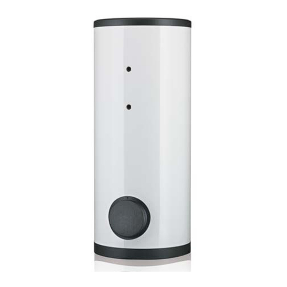
- Page 1 Indirecte boiler Indirect calorifier Ballon échangeur IT - 400/500/600/750/1000 0310 110 Installatie-, Gebruikers- en Servicehandleiding Installation, User and Service Manual Notice d’installation, Mode d’emploi, Notice d’entretien Innovation has a name.
- Page 3 IT 400 / 500 / 600 / 750 / 1000 Inhoudsopgave / Table of contents / Table des matières Deze handleiding bestaat uit 3 talen. 1 - NL Handleiding IT 400 t/m 1000 ....................5 2 - UK Manual IT 400 till 1000 ....................... 19 3 - FR Notice IT 400 à...
- Page 4 IT 400 / 500 / 600 / 750 / 1000...
- Page 5 IT 400 / 500 / 600 / 750 / 1000 Lees deze handleiding Waarschuwing zorgvuldig Lees deze handleiding zorgvuldig voordat u het toestel in gebruik neemt. Het niet lezen van deze handleiding en het niet opvolgen van de instructies in deze handleiding kan leiden tot ongevallen en schade aan personen en het toestel.
- Page 6 IT 400 / 500 / 600 / 750 / 1000...
-
Page 7: Table Des Matières
IT 400 / 500 / 600 / 750 / 1000 Inhoudsopgave Technische specificaties ....................9 Vloerbelasting ........................9 Watersamenstelling ......................9 Werkruimte ........................... 9 Algemene gegevens ......................9 Afmetingen ......................... 10 Installatie ........................... 11 Aansluitschema ........................11 Wateraansluitingen ......................11 Onderhoud ........................ - Page 8 IT 400 / 500 / 600 / 750 / 1000...
-
Page 9: Technische Specificaties
IT 400 / 500 / 600 / 750 / 1000 Technische specificaties Houd in verband met het gewicht van het toestel rekening met de maximale vloerbelasting, 1.1 Vloerbelasting zie de tabel (1.4 "Algemene gegevens"). Het toestel is bedoeld om drinkwater op te warmen. Het drinkwater moet voldoen aan de 1.2 Watersamen- regelgeving voor drinkwater voor menselijke consumptie. -
Page 10: Afmetingen
IT 400 / 500 / 600 / 750 / 1000 1.5 Afmetingen Eenheid IT 400 IT 500 IT 600 IT 750 IT 1000 Totale hoogte 1705 2040 1835 2030 2000 Diameter toestel 1060 Hoogte collector afvoer Hoogte collector toevoer 1010 1205 1145 1205... -
Page 11: Installatie
IT 400 / 500 / 600 / 750 / 1000 Installatie De figuur geeft het aansluitschema weer. Dit schema wordt gebruikt in de paragrafen waarin 2.1 Aansluitschema het eigenlijke aansluiten wordt beschreven. Legenda 2. inlaatcombinatie (verplicht) 3. T&P-ventiel (aanbevolen) 4. afsluiter (aanbevolen) 5. - Page 12 IT 400 / 500 / 600 / 750 / 1000 Let op Een inlaatcombinatie is verplicht. Monteer deze zo dicht mogelijk bij het toestel. Waarschuwing Tussen inlaatcombinatie en het toestel mag nooit een afsluiter of terugslagklep geplaatst worden. Warmwaterzijdig 2.2.2 Zie (B) in het aansluitschema (2.1 "Aansluitschema").
-
Page 13: Onderhoud
IT 400 / 500 / 600 / 750 / 1000 Onderhoud Let op Onderhoud mag alleen door een erkend service- en onderhoudsmonteur worden uitgevoerd. Bij elke onderhoudsbeurt dient de boiler waterzijdig onderhouden te worden. Het onderhoud dient in de volgende volgorde te worden uitgevoerd. 1. - Page 14 IT 400 / 500 / 600 / 750 / 1000 Werkvolgorde: 1. Draai de bouten van de reiningsopening los. 2. Verwijder de deksel en de pakking. 3. Inspecteer de tank en verwijder de losse kalkaanslag en verontreinigingen. 4. Indien de kalkaanslag niet handmatig verwijderd kan worden, dient ontkalkt te worden met een ontkalkingmiddel.
-
Page 15: Garantie
IT 400 / 500 / 600 / 750 / 1000 Garantie Indien binnen één jaar na de oorspronkelijke installatiedatum van een door A.O. Smith 4.1 Garantie geleverde boiler, na onderzoek en ter uitsluitende beoordeling van A.O. Smith, blijkt dat een algemeen deel of onderdeel, met uitzondering van de tank, niet of niet juist functioneert ten gevolge van fabricage- en/of materiaalfouten, zal A.O. -
Page 16: Uitsluitingen
IT 400 / 500 / 600 / 750 / 1000 De in artikel 1 en 2 bedoelde garantie geldt niet: 4.4 Uitsluitingen a. indien de boiler door een van buiten komende oorzaak is beschadigd; b. in geval van misbruik, verwaarlozing (met inbegrip van bevriezing), verandering, onjuist en/of afwijkend gebruik van de boiler en wanneer gepoogd is lekken te repareren;... - Page 17 IT 400 / 500 / 600 / 750 / 1000...
- Page 18 IT 400 / 500 / 600 / 750 / 1000...
- Page 19 IT 400 / 500 / 600 / 750 / 1000 Read this manual Warning carefully Read this manual carefully before starting the water heater. Failure to read the manual and to follow the printed instructions may lead to personal injury and damage to the water heater.
- Page 20 IT 400 / 500 / 600 / 750 / 1000...
- Page 21 IT 400 / 500 / 600 / 750 / 1000 Table of contens Technical specifications ....................23 Floor load ........................... 23 Water composition ......................23 Working clearance ......................23 General specifications ......................23 Dimensions ........................24 Installation ........................25 Installation diagram ......................25 Unvented water connections ....................
- Page 22 IT 400 / 500 / 600 / 750 / 1000...
-
Page 23: Technical Specifications
IT 400 / 500 / 600 / 750 / 1000 Technical specifications Allow for the water heater's weight and the maximum floor load; refer to the table (1.4 1.1 Floor load "General specifications"). The water heater is intended for heating drinking water. The drinking water must comply with 1.2 Water composition the regulations governing drinking water for human consumption. -
Page 24: Dimensions
IT 400 / 500 / 600 / 750 / 1000 1.5 Dimensions Unit IT 400 IT 500 IT 600 IT 750 IT 1000 Total height 1705 2040 1835 2030 2000 Diameter 1060 Height heat exchanger outlet Height heat exchanger inlet 1010 1205 1145... -
Page 25: Installation
IT 400 / 500 / 600 / 750 / 1000 Installation 2.1 Installation diagram This figuur shows the installation diagram. This diagram is referred to in the sections describing the actual connection procedure. VENTED UNVENTED IMD-0450 IMD-0449 Legend 1. pressure relief valve 11. -
Page 26: Unvented Water Connections
IT 400 / 500 / 600 / 750 / 1000 2.2 Unvented water Warning connections The installation should be carried out by a competent person, in compliance with general and locally applicable regulations. Cold water side 2.2.1 See (A) in the installation diagram (2.1 "Installation diagram"). - Page 27 IT 400 / 500 / 600 / 750 / 1000 2.3.2 Hot Water side See (B) in the installation diagram (2.1 "Installation diagram"). Note Insulating long hot water pipes prevents unnecessary energy loss. 1. Optional: fit a temperature gauge (12) so you can check the temperature of the tap water.
- Page 28 IT 400 / 500 / 600 / 750 / 1000...
-
Page 29: Maintenance
IT 400 / 500 / 600 / 750 / 1000 Maintenance Warning Maintenance may only be carried out by a competent person. At each service, the water heater undergoes maintenance on water side. The maintenance must be carried out in the following order. 1. - Page 30 IT 400 / 500 / 600 / 750 / 1000 Work order: 1. Undo bolts from the cover. 2. Remove cover and the gasket. 3. Inspect the tank and remove the losse scale deposits and contamination. 4. If the scale connot be removed by hand, descale the water heater with a desclaing agent.
-
Page 31: Warranty
IT 400 / 500 / 600 / 750 / 1000 Warranty If within one year of the original installation date of a water heater supplied by A.O. Smith, 4.1 General warranty following verification, and at the sole discretion of A.O. Smith, an assembly or part (with exclusion of the tank) proves to be defective or fails to function correctly due to manufacturing and/or material defects, then A.O. -
Page 32: Scope Of The Warranty
IT 400 / 500 / 600 / 750 / 1000 The obligations of A.O. Smith pursuant to the specified warranty are limited to free delivery 4.5 Scope of the from the warehouse of the replacement assemblies, parts or water heater, respectively. warranty Shipping, labour, installation and any other costs associated with the replacement will not be accepted by A.O. - Page 33 IT 400 / 500 / 600 / 750 / 1000...
- Page 34 IT 400 / 500 / 600 / 750 / 1000...
- Page 35 IT 400 / 500 / 600 / 750 / 1000 Veuillez lire attentivement Attention ce manuel Lisez attentivement ce manuel d'instructions avant de mettre l'appareil en service. Ce manuel d'instructions doit être lu scrupuleusement et les instructions de ce manuel d'instructions doivent être suivies sous peine d'accidents et de dégâts matériels et/ou de blessures corporelles.
- Page 36 IT 400 / 500 / 600 / 750 / 1000...
- Page 37 IT 400 / 500 / 600 / 750 / 1000 Table des matières Spécifications techniques ....................39 Charge maximale au sol l'appareil ..................39 Composition de l'eau ......................39 Espace de travail ........................ 39 Données générales ......................39 Dimensions ........................40 Installation ........................
- Page 38 IT 400 / 500 / 600 / 750 / 1000...
-
Page 39: Spécifications Techniques
IT 400 / 500 / 600 / 750 / 1000 Spécifications techniques Tenez compte de la charge maximale exercée sur le sol par le poids de l'appareil, voir le 1.1 Charge maximale tableau (1.4 "Données générales"). au sol de l'appareil L'appareil est destiné... -
Page 40: Dimensions
IT 400 / 500 / 600 / 750 / 1000 1.5 Dimensions Unité IT 400 IT 500 IT 600 IT 750 IT 1000 Hauteur totale 1705 2040 1835 2030 2000 Diamètre de l'appareil 1060 Hauteur sortie du échangeur Hauteur entrée du échangeur 1010 1205 1145... -
Page 41: Installation
IT 400 / 500 / 600 / 750 / 1000 Installation Cette illustration représente le schéma de raccordement. Ce schéma est utilisé dans les 2.1 Schéma de raccor- paragraphs suivants contenant une description du raccordement proprement dit. dement Légende 2. groupe de sécurité (obligatoire) 3. -
Page 42: Côte Eau Chaude
IT 400 / 500 / 600 / 750 / 1000 Attention Un groupe de sécurité est obligatoire. Montez-le le plus près possible de l'appareil. Avertissement Entre la combinaison d'entrée et l'appareil, vous ne pouvez jamais monter de vanne d'arrêt ou de clapet anti-retour. Côte eau chaude 2.2.2 Voir (B) du schéma de raccordement... -
Page 43: Effecteur L'entretien
IT 400 / 500 / 600 / 750 / 1000 Effecteur l'entretien Attention L'entretien ne peut êntre effectué que par un professionnel de la maintenance ou de l'entretien agréé. A chaque entretien, l'appareil doit être contrôlé côté eau et côté gaz. L'entretien doit s'effectuer dans l'ordre suivant. -
Page 44: Contrôle Des Anodes
IT 400 / 500 / 600 / 750 / 1000 Ordre du travail: 1. Faites tourner les boulons de l’ouverture de nettoyage. 2. Éliminez le couvercle et le joint. 3. Inspectez le réservoir. Éliminez la couche de calcaire accumulée et les saletés. 4. -
Page 45: Garantie
IT 400 / 500 / 600 / 750 / 1000 Garantie Si, durant l'année suivant la date initiale d'installation d'un chauffe-eau livré par A.O. Smith 4.1 Garantie générale après examen par et sur l'appréciation exclusive de A.O. Smith toute partie ou pièce, à l'exception de la cuve, ne fonctionne pas ou ne fonctionne pas correctement suite à... -
Page 46: Exclusions
IT 400 / 500 / 600 / 750 / 1000 La garantie visée dans les articles 1 et 2 ne couvre pas les cas suivants: 4.4 Exclusions a. si le chauffe-eau a subi des dégradation sous l'effet d'agents extérieurs; b. en cas de négligence (y compris exposition au gel), modification, usage incorrect et/ou abusif du chauffe-eau et lorsqu'on a essayé... - Page 47 IT 400 / 500 / 600 / 750 / 1000...
- Page 48 IT 400 / 500 / 600 / 750 / 1000 0310110 R0.0 NL/UK/FR...