Table des Matières
Publicité
Liens rapides
19147-6NL-04
PNOZ 11
Sicherheitsbestimmungen
• Das Gerät darf nur von Personen
installiert und in Betrieb genommen
werden, die mit dieser Betriebsanleitung
und den geltenden Vorschriften über
Arbeitssicherheit und Unfallverhütung
vertraut sind. Beachten Sie die VDE-
sowie die örtlichen Vorschriften, insbe-
sondere hinsichtlich Schutzmaßnahmen.
• Beim Transport, der Lagerung und im
Betrieb die Bedingungen nach EN 60068-
2-78 einhalten (s. technische Daten).
• Durch Öffnen des Gehäuses oder
eigenmächtige Umbauten erlischt jegliche
Gewährleistung.
• Montieren Sie das Gerät in einen
Schaltschrank; Staub und Feuchtigkeit
können sonst zu Beeinträchtigungen der
Funktionen führen.
• Sorgen Sie an allen Ausgangskontakten
bei kapazitiven und induktiven Lasten für
eine ausreichende Schutzbeschaltung.
Bestimmungsgemäße Verwendung
Das Sicherheitsschaltgerät dient dem
sicherheitsgerichteten Unterbrechen eines
Sicherheitsstromkreises.
Das Sicherheitsschaltgerät erfüllt Forderun-
gen der EN 60947-5-1, EN 60204-1 und
VDE 0113-1 und darf eingesetzt werden in
Anwendungen mit
• Not-Halt-Tastern
• Schutztüren
Das Gerät ist für die Absicherung von
berührungslosen Verdeckungen geeignet, da
ein dynamischer Start möglich ist.
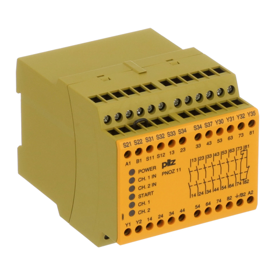
Gerätebeschreibung
Das Sicherheitsschaltgerät ist in einem
P-93-Gehäuse untergebracht. Es stehen
Gerätevarianten für verschiedene
Wechselspannungen zur Verfügung. Jede
Gerätevariante kann auch mit 24 V Gleich-
spannung betrieben werden.
Merkmale:
• Relaisausgänge: 7 Sicherheitskontakte
(S) und ein Hilfskontakt (Ö), zwangs-
geführt
• Anschlussmöglichkeit für Not-Halt-Taster,
Schutztürgrenztaster und Starttaster
• Statusanzeige
• Rückführkreis zur Überwachung externer
Schütze
• 2 Halbleiterausgänge melden Betriebs-
bereitschaft bzw. Störung bei Erd- oder
Querschluss
Das Schaltgerät erfüllt folgende Sicherheits-
anforderungen:
• Schaltung ist redundant mit Selbstüber-
wachung aufgebaut (EN 954-1 Kategorie 4).
• Sicherheitseinrichtung bleibt auch bei
Ausfall eines Bauteils wirksam.
• Bei jedem Ein-Aus-Zyklus der Maschine
wird automatisch überprüft, ob die Relais
der Sicherheitseinrichtung richtig öffnen
und schließen.
• Der AC-Teil hat einen kurzschlussfesten
Netztransformator, der DC-Teil eine
elektronische Sicherung.
Safety Regulations
• The unit may only be installed and
operated by personnel who are familiar
with both these instructions and the
current regulations for safety at work and
accident prevention. Follow VDE and
local regulations especially as regards
preventative measures.
• Transport, storage and operating
conditions should all conform to
EN 60068-2-78.
• Any guarantee is void following opening
of the housing or unauthorised
modifications.
• The unit should be panel mounted,
otherwise dampness or dust could lead to
function impairment.
• Adequate protection must be provided on
all output contacts especially with
capacitive and inductive loads.
Authorised Applications
The safety relay provides a safety-related
interruption of a safety circuit.
The safety relay meets the requirements of
EN 60947-5-1, EN 60204-1 and VDE 0113-1
and may be used in applications with
• E-STOP pushbuttons
• Safety gates
The device is suitable for non-contact
barriers (e.g. light curtains) because a
dynamic start is possible.
Description
The Safety Relay is enclosed in a
90 mm P-93 housing. There are variations
for different AC voltages. Every unit can
also be operated with 24 VDC.
Features:
• Relay outputs: 7 safety contacts (N/O)
and one auxiliary contact (N/C), positive-
guided.
• Connections for Emergency Stop Button,
Safety Gate Limit Switch and Reset
button.
• Status Indicators.
• Feedback Control Loop for monitoring of
external contactors/relays.
• 2 semi-conductor outputs show ready for
operation or earth fault or short circuit on
input channels.
The relay complies with the following safety
requirements:
• The circuit is redundant with built-in self-
monitoring (EN 954-1 Category 4).
• The safety function remains effective in
the case of a component failure.
• The correct opening and closing of the
safety function relays is tested
automatically in each on-off cycle.
• AC relays are fitted with a short-circuit
proof power transformer. DC relays have
an electronic fuse.
- 1 -
Conseils préliminaires
• La mise en oeuvre de l'appareil doit être
effectuée par une personne spécialisée
en installations électriques, en tenant
compte des prescriptions des différentes
normes applicables (NF, EN, VDE...)
notamment au niveau des risques
encourus en cas de défaillance de
l'équipement électrique.
• Respecter les exigences de la norme
EN 60068-2-78 lors du transport, du
stockage et de l'utilisation de l'appareil.
• L'ouverture de l'appareil ou sa modifi-
cation annule automatiquement la
garantie.
• L'appareil doit être monté dans une
armoire; l'humidité et la poussière
pouvant entraîner des aléas de
fonctionnement.
• Vérifiez que le pouvoir de coupure des
contacts de sortie est suffisant en cas de
circuits capacitifs ou inductifs.
Domaines d'utilisation
Le bloc logique de sécurité sert à interrompre
en toute sécurité un circuit de sécurité.
Le bloc logique de sécurité satisfait aux
exigences des normes EN 60947-5-1,
EN 60204-1 et VDE 0113-1 et peut être
utilisé dans des applications avec des
• poussoirs d'arrêt d'urgence
• protecteurs mobiles
L'appareil est adapté à la surveillance de
barrières immatérielles car une validation
dynamique est possible (surveillance du
circuit de réarmement).
Description de l'appareil
Inséré dans un boîtier P-93, le bloc logique
de sécurité est disponible en différentes
versions pour les tensions alternatives.
Chaque relais peut également être alimenté
en 24 V DC.
Particularités:
• Sorties disponibles: 7 contacts à
fermeture de sécurité et un contact à
ouverture pour signalisation
• Bornes de raccordement pour poussoirs
AU, détecteurs de position et poussoir de
validation
• LEDs de visualisation
• Boucle de retour pour l'auto-contrôle des
contacteurs externes
• 2 sorties statiquesd'information (relais en
position travail et défaut court-circuit ou
mise à la terre)
Le relais PNOZ 11 répond aux exigences
suivantes:
• conception redondante avec auto-
surveillance (selon EN 954-1 cat. 4)
• sécurité garantie même en cas de
défaillance d'un composant
• test cyclique (ouverture/fermeture des
relais internes) à chaque cycle Marche/
Arrêt de la machine
• transfo. interne protégé contre les c.c
(relais en AC)
• fusible électronique (relais en DC)
Publicité
Table des Matières

Manuels Connexes pour Pilz PNOZ 11


Sommaire des Matières pour Pilz PNOZ 11
- Page 1 The relay complies with the following safety Querschluss mise à la terre) requirements: Das Schaltgerät erfüllt folgende Sicherheits- Le relais PNOZ 11 répond aux exigences • The circuit is redundant with built-in self- anforderungen: suivantes: monitoring (EN 954-1 Category 4).
- Page 2 Reset with monitoring (Button in reset fait monter le relais Kx qui s'auto-maintient. Start mit Überwachung (Taster im circuit). La LED "Start" est allumée. Le PNOZ 11 Startkreis) By pressing the reset button, relay Kx n'est activé qu'au relâchement du poussoir Bei Betätigen des Starttasters zieht Relais...
-
Page 3: Montage
La fonction de détection de court-circuit nicht einfehlersicher ist, wird sie von Pilz As the function for detecting shorts across est testé par Pilz lors du contrôle final. Un während der Endkontrolle geprüft. Eine the inputs is not failsafe, it is tested by test sur site est possible de la façon... - Page 4 Emergency Stop wiring with manual les différents cablages possibles du und überwachtem Start, Schutztüran- and monitored reset. Safety gate controls PNOZ 11: poussoirs AU avec surveillance steuerungen sowie Kontaktvervielfachung as well as contact expansion via external du circuit de réarmement, interrupteurs durch externe Schütze dargestellt.
-
Page 5: Erreurs - Défaillances
Faults Erreurs - Défaillances • Erdschluss bei PNOZ 11 • Earth fault on PNOZ 11 • Défaut de masse du PNOZ 11 - Betrieb mit Wechselspannung: Die - AC operation: The supply voltage fails - AC: la tension d’alimentation s’effondre Versorgungsspannung bricht zusam- and the safety contacts are opened. -
Page 6: Technische Daten
Abmessungen in mm/Dimensions in mm/Dimensions en mm Technische Daten Technical Data Caractéristiques techniques Elektrische Daten Electrical data Données électriques Versorgungsspannung U Supply Voltage U Tension d’alimentation U 24 V DC 24 V, 42 V, 48 V, 110 ... 120 V, 230 ... 240 V AC Spannungstoleranz Voltage Tolerance Plage de la tension d’alimentation... - Page 7 SIL nach IEC 61511 SIL in accordance with IEC 61511 SIL selon IEC 61511 SIL 3 PFD nach IEC 61511 PFD in accordance with IEC 61511 PFD selon IEC 61511 2,03E-06 in Jahren in years en années Zeiten Times Temporisations Einschaltverzögerung Switch-on delay Temps de réarmement...
-
Page 8: Bestelldaten/Order Reference/Caractéristiques
Die vollständige EG-Konformitätserklärung The complete EC Declaration of Conformity Vous trouverez la déclaration de conformité finden Sie im Internet unter www.pilz.com is available on the Internet at www.pilz.com CE complète sur notre site internet Bevollmächtigter: Norbert Fröhlich, Authorised representative: Norbert Fröhlich, www.pilz.com... - Page 9 19147-6NL-04 PNOZ 11 Prescripciones de seguridad Norme di sicurezza Veiligheidsvoorschriften • El dispositivo tiene que ser instalado y • Il dispositivo può venire installato e • Het apparaat mag uitsluitend worden geïnstalleerd en in bedrijf genomen door puesto en funcionamiento exclusivamente messo in funzione solo da persone che por personas que estén familiarizadas,...
-
Page 10: Descripción Del Funcionamiento
Descripción del funcionamiento Functiebeschrijving Descrizione del funzionamento El dispositivo PNOZ 11 sirve para la Het relais PNOZ 11 dient om een beveili- Il modulo PNOZ 11 serve per interrompere interrupción, por motivos de seguridad, de gingscircuit met zekerheid te onderbreken. - Page 11 Pilz Een controle na de installatie van het errores, es probada por Pilz en el control durante il collaudo finale. Una verifica apparaat is als volgt mogelijk: final. Una verificación después de la dopo l’installazione del dispositivo può...
- Page 12 de la longitud máxima, pueden retardar 4. Ripristinare il fusibile: eliminare il 4. Zekering resetten: de kortsluiting el disparo del fusible en hasta 2 minutos. cortocircuito e disinserire per ca. 1 min ongedaan maken en de 4º Reponer nuevamente el fusible: retirar la tensione di alimentazione.
- Page 13 S11 S12 S11 S31 Fig. 2: Circuito de entrada monocanal, Fig. 3: Circuito de entrada monocanal, Fig. 4: Circuito de entrada bicanal, rearme rearme manual/Circuito di ingresso pulsador de rearme supervisado/Circuito di manual/Circuito di ingresso bicanale, start monocanale, start manuale/Eénkanalig ingresso monocanale, pulsante di start manuale/Tweekanalig ingangscircuit, ingangscircuit, handmatige start...
-
Page 14: Datos Técnicos
Dimensiones en mm/Dimensioni in mm/Afmetingen in mm Datos técnicos Dati tecnici Technische gegevens Datos eléctricos Dati elettrici Elektrische gegevens Tensión de alimentación U Tensione di alimentazione U Voedingsspanning U 24 V DC 24 V, 42 V, 48 V, 110 ... 120 V, 230 ... - Page 15 PFD según IEC 61511 PFD secondo IEC 61511 PFD volgens IEC 61511 2,03E-06 en años in anni in jaren Tiempos Tempi Tijden Retardo a la conexión Ritardo d’inserzione Inschakelvertraging rearme automático start automatico automatische start typ. 330 ms, max. 450 ms rearme automático tras conexión de start automatico dopo attivazione automatische start na...
-
Page 16: Declaración Ce De Conformidad
CE è disponibile in Internet Gevolmachtige: Norbert Fröhlich, Internet www.pilz.com all’indirizzo www.pilz.com Pilz GmbH & Co. KG, Felix-Wankel-Str. 2, Apoderado: Norbert Fröhlich, Mandatario: Norbert Fröhlich, 73760 Ostfildern, Duitsland Pilz GmbH & Co. KG, Felix-Wankel-Str. 2, Pilz GmbH &...