
Manuels Connexes pour HOMCOM A91-234V00


Sommaire des Matières pour HOMCOM A91-234V00
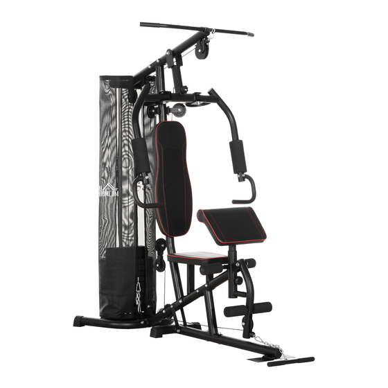
- Page 1 IN230600152V01_FR A91-234V00 STATION DE MUSCULATION 150KG Max 150kg IMPORTANT : A LIRE ATTENTIVEMENT ET À CONSERVER POUR CONSULTATION ULTÉRIEURE. INSTRUCTIONS D’ASSEMBLAGE...
- Page 2 PACKING DETALS:TOTAL 4 BOXES BOX-1/4 Boîte d'accessoires Boîte d'accessoires Description Qté Description Qté Description Qté Poulie Cadre de Support base Poulie Poulie A Support à deux voies Stabilisateur pour Poulie arrière Support de Capuchon poulie Petite poulie Tube de Sangle de support de la connexion selle...
- Page 3 PACKING DETALS:TOTAL 4 BOXES BOX-2/4 BOX-3/4 Qté Qté Description Description Pile de poids Bras papillon - 10 Lbs Gauche / Droit Tige de selle Tube de pont BOX-4/4 Qté Description Barre de traction Pile de poids 10 Lbs Mousse Bras de papillon Pile de poids 8 Lbs...
- Page 4 Introduction Sécurité et Avertissements Vue d'ensemble Assemblage...
- Page 9 INTRODUCTION servant des barres latérales.
- Page 10 VUE D’ENSEMBLE Ajouter une pièce de connexion...
- Page 11 Pièce Description QTÉ Pièce Description QTÉ Cadre de base Ecrou en nylon M10 Tige de selle Écrou en nylon M12 Stabilisateur Goupille fixe pour la pile arrière de poids Tube de support Capuchon d'extrémité de la selle Tube de support Bouchon rond du montant Tube de support...
- Page 12 Boulon à tête hex Pile de poids 10 Lbs M10 x 45mm Boulon à tête hex Câble Barre de traction M10 x 75mm Boulon à tête hex Câble Bras papillon M10 x 70 mm Boulon à tête hex Câble Barre de tirage M12 x 80mm inférieur Boulon à...
- Page 13 ASSEMBLAGE Étape A: -11-...
- Page 14 -12-...
- Page 15 Étape B: -13-...
- Page 16 entrent bien dans les trous. 5. Insérer la douille de la l'aide de la goupille fixe -14-...
- Page 17 Étape C: -15-...
- Page 18 -16-...
- Page 19 Étape D: -17-...
- Page 20 -18-...
- Page 21 -19-...
- Page 22 Étape E: -20-...
- Page 23 anneaux en métal pulvérulent du support. 4.Enfiler la mousse du bras - ajuster à la position souhaitée. -21-...
- Page 24 et trois boulons à tête hexagonale Répéter l'opération pour le bras -22-...
- Page 25 Étape F: -23-...
- Page 26 -24-...
- Page 27 Étape G: -25-...
- Page 28 -26-...
- Page 29 Étape H: -27-...
- Page 30 -28-...
- Page 31 Étape I: -29-...
- Page 32 IN230600152V01_FR A91-234V00 150KG Max 150kg...
- Page 33 PACKING DETALS:TOTAL 4 BOXES BOX-1/4 Accessory Box Accessory Box Description Description Description Bracket for pulley Base frame bulley Two way bracket for pulley A bulley Rear stabiliser 20 bulley bracket Cap for small pully Seat support connection tube strap Cable for lat Rubber ring Upright support tube...
- Page 34 PACKING DETALS:TOTAL 4 BOXES BOX-2/4 BOX-3/4 Description Description butterfly arm weight plate Seat post bridge tube BOX-4/4 Description lat bar weight plate foam for butterfly arm weight plate foam for leg curl elbow cushion bracket for cloth cover leg curl tube cushion support tube select bar...
- Page 35 Introduction Safety & Warnings Overview Assembly...
- Page 40 INTRODUCTION...
- Page 41 OVERVIEW...
- Page 43 -10-...
- Page 44 ASSEMBLY Step A: -11-...
- Page 45 -12-...
- Page 46 Step B: 2. Repeat for the right side of the rear stabiliser. -13-...
- Page 47 the holes. 5. Place the bushing for secure in place using the -14-...
- Page 48 Step C: -15-...
- Page 49 -16-...
- Page 50 Step D: -17-...
- Page 51 -18-...
- Page 52 -19-...
- Page 53 Step E: diagram. -20-...
- Page 54 2. Attach the right butterfly arm onto the bracket on the upright bracket. 4. Put the foam for the butterfly adjust to your desired position. -21-...
- Page 55 tighten using three curve washers Repeat for the left butterfly arm onto both sides of the upright -22-...
- Page 56 Step F: -23-...
- Page 57 -24-...
- Page 58 Step G: -25-...
- Page 59 -26-...
- Page 60 Step H: 1. Attach the end with the stopper ball of the cable for the lower pull -27-...
- Page 61 -28-...
- Page 62 Step I: -29-...