Emerson AVENTICS AF2 Instructions De Montage
Masquer les pouces
Voir aussi pour AVENTICS AF2:
- Notice d'instruction (137 pages) ,
- Description du système (51 pages) ,
- Notice d'instruction (37 pages)
Publicité
Les langues disponibles
Les langues disponibles
Liens rapides
Montageanleitung | Assembly instructions | Instructions de montage
Istruzioni di montaggio | Instrucciones de montaje | Monteringsanvisning
R412026496–BAL–001–AC
2023-12; Replaces: 2022-04
DE/EN/FR/IT/ES/SV
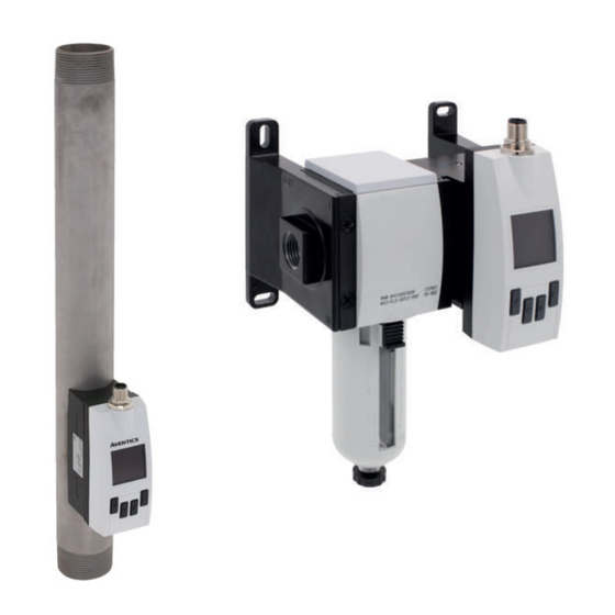
AVENTICS™ AF2
Durchflusssensor
Flow sensor
Capteur de débit
Flussometro
Sensor de caudal
Flödessensor
Publicité

Manuels Connexes pour Emerson AVENTICS AF2


Sommaire des Matières pour Emerson AVENTICS AF2
- Page 1 Montageanleitung | Assembly instructions | Instructions de montage Istruzioni di montaggio | Instrucciones de montaje | Monteringsanvisning R412026496–BAL–001–AC 2023-12; Replaces: 2022-04 DE/EN/FR/IT/ES/SV AVENTICS™ AF2 Durchflusssensor Flow sensor Capteur de débit Flussometro Sensor de caudal Flödessensor...
- Page 2 Inhaltsverzeichnis Zu dieser Dokumentation........................................Gültigkeit der Dokumentation......................................Zusätzliche Dokumentationen ......................................Verwendete Abkürzungen........................................ Sicherheit............................................Zu diesem Kapitel..........................................Bestimmungsgemäße Verwendung ....................................Nicht bestimmungsgemäße Verwendung..................................Pflichten des Betreibers ........................................Qualifikation des Personals....................................... Gefahrenquellen ..........................................2.6.1 Verletzungsgefahr ......................................2.6.2 Materialschäden......................................... Lieferumfang ............................................. Transport und Lagerung........................................Produkt transportieren ........................................
- Page 3 9.1.3 Vorgehen ........................................... Reinigung............................................9.2.1 Allgemeine Vorgaben ......................................9.2.2 Vorgehen ........................................... Wartung............................................Nach der Instandhaltung ........................................10 Demontage und Austausch ........................................ 10 10.1 Grundlegende Vorgaben ........................................10.2 Vorbereitung............................................ 11 Entsorgung ............................................12 Fehlersuche und Fehlerbehebung....................................... 10 12.1 Vorgehen ............................................12.2 Fehlerbilder ............................................13 Technische Daten..........................................
- Page 4 QR-Code Beschreibung samtanlage beachten. Downloads und weiterführende Informationen zu die- sem Produkt finden Sie auf der Produktseite im Emerson 2.5 Qualifikation des Personals Store. Ausschließlich für die Aufgaben qualifiziertes Personal darf die Tätigkeiten aus- führen, die in dieser Dokumentation beschrieben werden. Je nach Tätigkeit sind grundlegende Kenntnisse in folgenden Bereichen und Kenntnisse der zugehöri-...
- Page 5 – 1x Sensor (siehe: bestellte Konfiguration) AS2-AF2-FLX- DN08 G3/8 Innengewinde Variante mit W05 Das Produkt wurde individuell mit dem Internet-Konfigurator von G038 Emerson konfiguriert. Während der Konfiguration wird eine individuel- AS3-AF2-FLX- DN15 G1/2 Innengewinde Konfiguratorvariante le Materialnummer generiert. Die Materialnummer stimmt genau mit G012-CON der ausgelieferten Konfiguration überein.
- Page 6 5.2.2 Standardkomponenten 5.2.4 Variante HF Ø D3 Ø D1 A: 18 B: 14,5 Abb. 1: Produktübersicht 1 Gerätestecker 2 Display 3 Bedientasten 5.2.3 Variante AS 45,5 M12x1 Ø D2 35,5 45,5 Abb. 3: Abmessungen Sensor Variante HF Abb. 2: Abmessungen Sensorfilterkombination Variante AS A IO-Link B Ethernet A IO-Link...
- Page 7 • Auf dem Typenschild. • In Druckluftnetzwerken das Produkt nach dem Lufttrockner montieren. Falls kein Lufttrockner vorhanden ist: Produkt nach dem Kondensatabscheider und geeigneten Filtern installieren. 5.4 Display Hinweise für Variante AS-AF2 Im Normalbetrieb zeigt das Display in der Standardanzeige folgende Werte und Symbole an: •...
- Page 8 Hinweise für Variante AS-AF2 2. Durchflusssensor mit dem Verblockungssatz verbinden, der zur Leitung passt. 3. Gerätekombination montieren. • Nach der Montage des Produkts mit einem Verblockungssatz oder Befesti- gungsbügel: Auf dichte Verschraubung achten. 4. Leitungsabschnitt unter Druck setzen. • Montage mit Befestigungsbügel: siehe g Abb. 5. 5.
- Page 9 Anschluss mit 5-poligem M12-Stecker 7 Inbetriebnahme Vorgehen 7.1 Grundlegende Vorgaben 1. M12x1-Stecker des Verbindungskabels CON-RD auf den Anschluss (siehe g Abb. 2) schrauben. Vorgaben für das Produkt Falls der Anschluss nicht verwendet wird, Schutzart IP65 des Gehäuses erhal- ten: Anschluss mit Kappe abdecken. 7.2 Vorbereitung 2.
- Page 10 9.1.2 Vorbereitung 11 Entsorgung Schutzmaßnahmen durchführen. Siehe g 6.2.3 Schutzmaßnahmen durch- Nicht bestimmungsgemäßes Entsorgen führt zu Umweltverschmutzungen. Roh- führen. stoffe können dann nicht mehr wiederverwertet werden. Das Produkt, die Verpackung und eventuell ausgetretene Betriebsmittel nach 9.1.3 Vorgehen den geltenden Landesbestimmungen entsorgen. Sichtkontrolle Eine Sichtkontrolle auf Unversehrtheit durchführen.
- Page 11 [3:4:4]) 13 Technische Daten • ± 8 % des Messwerts, + 1 % (Full Scale) des erweiterten Messbereichs Dieses Kapitel enthält einen Auszug der wichtigsten Technischen Daten. Weitere Technische Daten finden Sie auf der Produktseite im Emerson Store. Druckmessung Messbereich 0 … 16 bar Messgenauigkeit ≤ ± 1,5 % des Messbereichs (im Bereich Allgemein 10 … 30 °C)
- Page 12 • DN50: R2 oder 2" NPT Reproduzierbarkeit ≤ ± 0,2 % des Messbereichs Referenzbedingungen nach DIN 1343: atmosphärischer Druck 1,01325 bar abs. Druckluft- temperatur 0 °C. 14 Zubehör Montage Hinweise zu Zubehör finden Sie auf der Produktseite im Emerson Store. Spezifikation Beschreibung Artikel-Nr. Einbaulage Beliebig Verbindungskabel, Serie CON-RD, M12x1...
- Page 13 Table of contents About this documentation ......................................... 15 Documentation validity........................................Additional documentation ....................................... Abbreviations used........................................... Safety..............................................About this chapter..........................................Intended use ............................................ Improper use............................................ Obligations of the operator ......................................Personnel qualifications........................................Hazards ............................................2.6.1 Danger of injury ......................................... 2.6.2 Material damage ........................................ Scope of delivery ..........................................
- Page 14 9.1.3 Procedure .......................................... Cleaning ............................................9.2.1 General requirements ......................................9.2.2 Procedure .......................................... Maintenance ............................................ After service ............................................. 10 Disassembly and exchange......................................... 21 10.1 Basic requirements........................................... 10.2 Preparation ............................................11 Disposal ............................................. 12 Troubleshooting ..........................................12.1 Procedure............................................12.2 Malfunction types..........................................13 Technical data ............................................ 14 Accessories ............................................
- Page 15 2.5 Personnel qualifications Downloads and further information on this product can be found on the product page at the Emerson Store. Only personnel qualified for the tasks at hand are allowed to perform the activi- ties described in this documentation. Depending on the activity, this requires ba-...
- Page 16 2" NPT external thread N200-CON 5 Product description 5.1 Brief description The flow sensor is available in 22 variants. See g 5.2.1 Overview of product vari- ants. Further information can be found on the product page in the Emerson store. AVENTICS™ AF2 | R412026496–BAL–001–AC | English...
- Page 17 5.2.2 Standard components 5.2.4 HF variant Ø D3 Ø D1 A: 18 B: 14,5 Fig. 1: Product overview 1 Device plug 2 Display 3 Control buttons 5.2.3 AS variant 45,5 M12x1 Ø D2 35,5 45,5 Fig. 3: HF variant sensor dimensions Fig. 2: Dimensions of AS variant sensor filter combination A IO-Link B Ethernet A IO-Link...
- Page 18 • On the name plate. • In compressed air networks, mount the product downstream of the air dryer. If there is no air dryer: Install the product downstream of the condensate sep- arator and suitable filters. 5.4 Display Notes for variant AS-AF2 In normal mode, the display shows the following values and icons in the standard screen: •...
- Page 19 • Assembly with block assembly kit (without air preparation unit): see g Fig. 7. Procedure Assembly option with mounting bracket 1. Check the flow direction that is indicated on the marking on the product. 2. Align the product observing the flow direction of the measuring medium (in- put left, output right).
- Page 20 Table 7: Pin assignment M12 plug, 5-pin 7.3 Step-by-step commissioning Contact Identifica- Wire color Description Procedure (M12) tion Brown Supply voltage Apply operating voltage. White Analog current output 4 … 20 mA INFO: The product has no main switch. The product is switched on and opera- (scalable) tional as soon as the product is connected to mains voltage.
- Page 21 • Check the product functions. Step 2: Check the product 1. Make sure the system or system part is not under pressure or voltage. 9.2 Cleaning 2. Check the product based on the fault patterns described below. 3. Perform troubleshooting using the information under “Remedy”. 9.2.1 General requirements If the malfunction cannot be eliminated as described under “Remedy”: Disas- semble the product and return it.
- Page 22 This section contains an excerpt of the most important technical data. Further scale) of the upper end value for the ex- ISO 8573-1:2021 [3:4:4]) technical data can be found on the product page in the Emerson store. tended measurement range General •...
- Page 23 Specifications Process connection • DN40: R1 ½ or 1 ½" NPT • DN50: R2 or 2" NPT 14 Accessories Information on accessories can be found on the product page in the Emerson store. Description Item no. Connecting cable, CON-RD, M12x1 series R412027647...
- Page 24 Table des matières A propos de cette documentation ...................................... 26 Validité de la documentation......................................Documentation supplémentaire ...................................... Abréviations utilisées........................................Sécurité.............................................. À propos de ce chapitre ........................................Utilisation conforme......................................... Utilisation non conforme........................................Obligations de l’exploitant ....................................... Qualification du personnel ....................................... Sources de danger..........................................2.6.1 Risque de blessure......................................
- Page 25 9.1.3 Procédure .......................................... Nettoyage ............................................9.2.1 Spécifications générales..................................... 9.2.2 Procédure .......................................... Maintenance ............................................ Après l’entretien..........................................10 Démontage et remplacement ......................................32 10.1 Spécifications de base ........................................10.2 Préparation ............................................11 Elimination............................................12 Recherche et élimination de défauts....................................32 12.1 Procédure............................................12.2 Erreurs possibles..........................................
- Page 26 Des téléchargements et informations additionnelles sur l’influence de l’alcool, d’autres drogues ou de médicaments qui affectent leur ce produit sont disponibles sur la page dédiée au pro- duit dans l’Emerson Store. capacité de réaction. • L’exploitant doit garantir l’utilisation d’EPI. Respecter les directives de l’instal- lation complète.
- Page 27 G038-CON Le produit a été configuré individuellement avec le configurateur In- AS2-AF2-FLX- DN08 Taraudage G3/8 Variante avec W05 ternet d’Emerson. Pendant la configuration, une référence individuelle G038 est générée. Cette référence correspond exactement à la configura- AS3-AF2-FLX- DN15 Taraudage G1/2 Variante de configurateur tion livrée.
- Page 28 Tab. 4: Variante HF IO-Link 5.2.4 Variante HF Désignation Diamètre Raccord de processus Remarque Ø D3 Ø D1 nominal HF-AF2-FLX- DN40 Filetage R1 ½ Filetage R est combinable avec ta- R112-CON raudage R et taraudage G HF-AF2-FLX- DN40 Filetage 1 ½ " NPT N112-CON HF-AF2-FLX- DN50 Filetage R2...
- Page 29 • Sur la plaque signalétique. • Dans les réseaux d’air comprimé, monter le produit en aval du dessiccateur d’air. En l’absence de dessiccateur d’air : installer le produit en aval du sépara- teur d’eau condensée et des filtres appropriés. 5.4 Affichage Consignes pour la variante AS-AF2 En fonctionnement normal, l’afficheur standard indique les valeurs et symboles suivants :...
- Page 30 AVERTISSEMENT! Une installation du produit hors de la plage de tempéra- ture de processus spécifiée et/ou de la température ambiante, indépendam- ment de l’état de fonctionnement, constitue un risque de sécurité en raison de fuites potentielles (prévention des accidents). Consignes pour la variante AS-AF2 •...
- Page 31 • Variante Ethernet : RJ45 Raccord à 8 pôles M12x1. Voir g 6.3.2.2 Raccord avec connecteur à 8 pôles M12. Remarques • Pour le raccordement, utiliser des câbles de connexion AVENTICS de la série CON-RD, M12x1. • Veiller à la conformité de la tension d’alimentation (protection du matériel). •...
- Page 32 2. Retirer tous les dépôts de poussière sur le produit et les parties adjacentes de 8.1 Spécifications générales l’installation. Spécifications générales 3. Le cas échéant, retirer d’autres dépôts liés à la production sur le produit et les parties adjacentes de l’installation. •...
- Page 33 Ce chapitre contient un extrait des principales données techniques. D’autres don- spécifiée. nées techniques sont disponibles sur la page dédiée au produit dans l’Emerson Voltage low for Q2/a, Qa Tension à Q2/a, Qa trop basse. Mettre la tension à la valeur Store.
- Page 34 Conditions de référence DIN 1343 : pression atmosphérique 1,01325 bar abs. tempéra- 14 Accessoires ture de l’air comprimé 0 °C. Montage Des informations relatives aux accessoires sont disponibles sur la page dédiée au produit dans l’Emerson Store. Spécification Description Référence Position de montage Indifférente Câbles de connexion, série CON-RD, M12x1...
- Page 35 Indice Sulla presente documentazione ......................................37 Validità della documentazione ......................................Documentazione aggiuntiva ......................................Abbreviazioni utilizzate ........................................Sicurezza............................................Sul presente capitolo........................................Uso a norma ............................................. Uso non a norma ..........................................Obblighi del gestore ......................................... Qualifica del personale ........................................Fonti di pericolo..........................................2.6.1 Pericolo di lesioni .......................................
- Page 36 9.1.3 Procedura .......................................... Pulizia............................................... 9.2.1 Disposizioni generali ......................................9.2.2 Procedura .......................................... Manutenzione ..........................................Dopo la manutenzione ........................................10 Smontaggio e sostituzione ......................................... 43 10.1 Disposizioni di base .......................................... 10.2 Preparazione ............................................ 11 Smaltimento ............................................12 Ricerca e risoluzione errori ......................................... 43 12.1 Procedura............................................
- Page 37 Per i download e per maggiori informazioni sul prodotto cool, altre droghe o farmaci che ne compromettano la capacità di reazione. consultare la pagina del prodotto nell'Emerson Store. • L'operatore deve garantire l'utilizzo del PSA. Rispettare le disposizioni dell'im- pianto.
- Page 38 DN08 Filettatura interna G3/8 Variante con W05 Il prodotto è stato configurato individualmente con il configuratore In- G038 ternet di Emerson. Durante la configurazione viene generato un codice individuale. Questo codice coincide esattamente con la configurazione AS3-AF2-FLX- DN15 Filettatura interna G1/2 Variante configuratore G012-CON fornita.
- Page 39 5.2.2 Componenti standard 5.2.4 Variante HF Ø D3 Ø D1 A: 18 B: 14,5 Fig. 1: Panoramica sul prodotto 1 Connettore dell’apparecchio 2 Display 3 Tasti di comando 5.2.3 Variante AS 45,5 M12x1 Ø D2 35,5 45,5 Fig. 3: Dimensioni sensore variante HF Fig. 2: Dimensioni combinazione filtri sensori variante AS A IO-Link B Ethernet...
- Page 40 • Sulla parte posteriore del prodotto. • Nelle reti dell’aria compressa montare il prodotto a valle del deumidificatore. In mancanza di deumidificatore montare il prodotto a valle del separatore di • Sulla targhetta di identificazione. condensa e installare filtri adeguati. 5.4 Display Note per la variante AS-AF2 •...
- Page 41 Note per la variante AS-AF2 Opzione di montaggio con set per il montaggio in batteria • Dopo il montaggio del prodotto con un set per il montaggio in batteria o con 1. Allineare il prodotto osservando la direzione di flusso del fluido di misurazione staffa di fissaggio: osservare che l’attacco sia a tenuta.
- Page 42 Attacco con connettore M12 a 5 poli Contatto RJ45 Colore con- Identificazione 10/100 Mbit (M12) duttore Procedimento Bianco/marro- POE- 1. Avvitare il connettore M12x1 del cavo di collegamento CON-RD all’attacco (vedere g Fig. 2). Marrone POE- Se l’attacco non viene utilizzato, conservare il tipo di protezione IP65 del cor- po: chiudere l’attacco con un coperchio.
- Page 43 • Elevate quantità di sporcizia 7. Svitare il flussometro dall’attacco di mandata (attacco filettato) con l’ausilio di una chiave fissa o estrarre il flussometro linearmente dal raccordo ad innesto. • Vicinanza a liquidi o vapori che sciolgono i grassi In presenza di condizioni ambientali aggressive si applicano ulteriori disposizioni per l'ispezione: 11 Smaltimento •...
- Page 44 ISO 8573-1:2021 [3:4:4]) Il presente capitolo contiene un estratto dei principali dati tecnici. Per maggiori misurazione ampliato informazioni sui dati tecnici consultare la pagina del prodotto nell'Emerson Store. • ±8 % del valore misurato, + 1 % (Full Sca- le) del campo di misurazione ampliato Generalità...
- Page 45 Condizioni di riferimento secondo la norma DIN 1343: pressione atmosferica 1,01325 bar, temperatura ass. aria compressa 0 °C. 14 Accessori Montaggio Per maggiori informazioni sugli accessori consultare la pagina del prodotto Specifiche nell'Emerson Store. Posizione di montaggio A scelta Descrizione N° art. Specifiche elettriche...
- Page 46 Índice de contenidos Acerca de esta documentación......................................48 Validez de la documentación......................................Documentación adicional......................................... Abreviaturas utilizadas ........................................Seguridad ............................................Acerca de este capítulo........................................Uso previsto ............................................. Uso no previsto ..........................................Obligaciones de la empresa explotadora ..................................Cualificación del personal ......................................... Fuentes de peligro..........................................
- Page 47 9.1.3 Procedimiento ........................................Limpieza............................................9.2.1 Especificaciones generales ....................................9.2.2 Procedimiento ........................................Mantenimiento ..........................................Tras el mantenimiento ........................................10 Desmontaje y sustitución ........................................54 10.1 Especificaciones básicas ........................................10.2 Preparación ............................................11 Eliminación ............................................12 Localización de fallos y su eliminación ....................................54 12.1 Procedimiento..........................................
- Page 48 Encontrará descargas y más información sobre este pro- alcohol, otras drogas o medicamentos que afecten a su capacidad de reac- ducto en la página del producto en Emerson Store. ción. • El usuario deberá garantizar el uso de equipo de protección individual (EPI).
- Page 49 El producto se ha configurado individualmente con el configurador de AS3-AF2-FLX- DN15 Rosca interior G1/2 Variante con W05 Internet de Emerson. Durante la configuración, se genera un número G012 de material individual. El número de material coincide exactamente AS3-AF2-FLX- DN15...
- Page 50 5.2.4 Variante HF Denominación Anchura no- Conexión del proceso Comentario minal Ø D3 Ø D1 HF-AF2-FLX- DN40 Rosca exterior NPT de N112-CON 1 ½ " HF-AF2-FLX- DN50 Rosca exterior R2 La rosca exterior R puede combi- R200-CON narse con la rosca interior R y la rosca interior G HF-AF2-FLX- DN50...
- Page 51 • En la placa de características. • En las redes de aire comprimido, montar el producto después del secador de aire. Si no hay secador de aire: instalar el producto después del separador de condensado y los filtros adecuados. 5.4 Pantalla Notas para la variante AS-AF2 En funcionamiento normal, la pantalla muestra los siguientes valores y símbolos en la pantalla estándar:...
- Page 52 Notas para la variante AS-AF2 Opción de montaje con el juego de unión • Después de montar el producto con un juego de unión o un soporte de fija- 1. Orientar el producto teniendo en cuenta la dirección de flujo del medio de ción: asegurarse de que la unión atornillada sea firme.
- Page 53 – El conector redondo está fijado. Contacto RJ45 Color del ca- Identificación 10/100 Mbit (M12) Conexión con conector M12 de 5 polos Azul POE+ Procedimiento Blanco/ma- POE- rrón 1. Atornillar el conector M12x1 del cable de unión CON-RD en la conexión (véase Marrón POE- g Fig. 2).
- Page 54 Uso en condiciones ambientales agresivas ¡PELIGRO! Purgar lentamente la instalación para evitar movimientos descon- trolados de los componentes de la instalación. Las condiciones ambientales agresivas son, p. ej.: 3. Asegurar la instalación contra reconexiones. • Temperatura elevada 4. Dejar que el producto y las piezas de la instalación contiguas se enfríen. •...
- Page 55 Este capítulo incluye un resumen de los datos técnicos más importantes. Encon- valor final superior del margen de medi- ISO 8573-1:2021 [3:4:4]) trará más datos técnicos en la página del producto en Emerson Store. ción ampliado • ±8 % del valor medido para el margen de Generalidades medición estándar, 1 % (Full Scale) del va-...
- Page 56 ≤ ± 0,2 % del margen de medición Condiciones de referencia según DIN 1343: presión atmosférica 1,01325 bar a temperatu- ra absoluta del aire comprimido 0 °C. 14 Accesorios Montaje Encontrará indicaciones sobre accesorios en la página del producto en Emerson Especificación Store. Posición de montaje Arbitrario Descripción...
- Page 57 Innehållsförteckning Om denna dokumentation ......................................... 59 Dokumentationens giltighet ......................................Ytterligare dokumentation....................................... Förkortningar som används ......................................Säkerhet ............................................Om detta kapitel ..........................................Ändamålsenlig användning ......................................Ej ändamålsenlig användning ......................................Den driftsansvariges skyldigheter..................................... Personalens kvalifikationer ....................................... Farokällor ............................................2.6.1 Risk för personskador ......................................2.6.2 Materialskador ........................................
- Page 58 9.1.3 Tillvägagångssätt ....................................... Rengöring ............................................9.2.1 Allmänna föreskrifter ......................................9.2.2 Tillvägagångssätt ....................................... Underhåll ............................................Efter underhåll..........................................10 Demontering och byte ........................................65 10.1 Grundläggande föreskrifter ......................................10.2 Förberedelse ............................................ 11 Avfallshantering..........................................12 Felsökning och åtgärder........................................65 12.1 Tillvägagångssätt ..........................................12.2 Felbeskrivningar ..........................................13 Tekniska data .............................................
- Page 59 Hämtningar och ytterligare information om den här Endast personal som är kvalificerad för uppgifterna får utföra aktiviteterna som produkten finns på produktsidan i Emerson Store. beskrivs i denna dokumentation. Dessa aktiviteter kräver grundläggande kunskaper inom följande områden liksom kunskaper om tillhörande fackbegrepp: •...
- Page 60 Flödessensorn finns tillgänglig i 22 varianter. Se g 5.2.1 Översikt över OBS! VPN, brandväggar och andra programvarubaserade produkter kan produktvarianter. Ytterligare information finns på produktsidan i Emerson Store. uppvisa säkerhetsbrister. Säkerheten vid VPN-användning kan bara vara lika hög som säkerheten för de anslutna apparaterna. Använd därför alltid den senaste versionen av VPN, brandväggar och andra programvarubaserade...
- Page 61 5.2.2 Standardkomponenter 5.2.4 Variant HF Ø D3 Ø D1 A: 18 B: 14,5 Bild 1: Produktöversikt 1 Apparatkontakt 2 Display 3 Manöverknappar 5.2.3 Variant AS 45,5 M12x1 Ø D2 35,5 45,5 Bild 3: Mått sensor variant HF Bild 2: Mått sensorfilterkombination variant AS A IO-Link B Ethernet A IO-Link...
- Page 62 Information för varianten AS-AF2 5.4 Display • Montera inte produkten omedelbart bakom en regulator eller filterregulator. I normal drift visar displayen som standard dessa värden och symboler: Använd endast den föreskrivna filterproduktvarianten. Ethernet Omgivningsförhållanden Info Info active Warn/Err Warning/Error active •...
- Page 63 • Montering med blockmonteringssats (utan luftbehandlingsenhet): se g Bild 7. Tillvägagångssätt Monteringsalternativ med fästbygel 1. Kontrollera flödesriktningen som anges i präglingarna på produkten. 2. Anpassa produkten med hänsyn till flödesriktningen för mätmediet (ingång till vänster, utgång till höger). 19 x 1,8 23 x 2 3.
- Page 64 Tab. 7: Stiftbeläggning för 5-polig M12-hankontakt 7.3 Driftstart steg för steg Kontakt Identifierin Trådfärg Beskrivning Tillvägagångssätt (M12) Brun Matningsspänning Anslut driftspänningen. Analog spänningsutgång 4–20 mA INFO: Produkten har ingen huvudbrytare. Produkten är inkopplad och (skalbar) driftklar så snart den är ansluten till nätspänningen. För att stänga av: separera Blå...
- Page 65 Steg 2: Kontrollera produkten 9.2 Rengöring 1. Se till att anläggningen resp. anläggningsdelen är trycklös och spänningsfri. 2. Kontrollera produkten med hjälp av felbeskrivningarna som följer. 9.2.1 Allmänna föreskrifter 3. Åtgärda fel med hjälp av informationen under ”Åtgärder”. Rengöringsintervaller Om du inte kan åtgärda felet med hjälp av beskrivningen: Demontera •...
- Page 66 övre slutvärdet för det utökade ISO 8573-1:2021 [3:4:4]) mätområdet Det här kapitlet innehåller ett utdrag från de tekniska data som är viktigast. • ±8 % av mätvärdet, +1 % (Full Scale) för Ytterligare tekniska data finns på produktsidan i Emerson Store. det utökade mätområdet Allmänt Tryckmätning Mätområde 0 … 16 bar...
- Page 67 Tab. 19: Data för variant HF-AF2 Specifikation Processanslutning • DN40: R1 ½ eller 1 ½" NPT • DN50: R2 eller 2" NPT 14 Tillbehör Information om tekniska data finns på produktsidan i Emerson Store. Beskrivning Artikelnummer Kabel, serie CON-RD, M12x1 R412027647 AVENTICS™ AF2 | R412026496–BAL–001–AC | Svenska...
- Page 68 The Emerson logo is a trademark and service mark of Emerson Electric Co. AVENTICS is a mark Further addresses: of one of the Emerson Automation Solutions family of business units. All other marks are pro- www.emerson.com/contactus...