Publicité
Liens rapides
English
M
OUNTING THE UNIT
ATS Control panel or
Depending on the type of enclosure and the battery
4-door/4-lift DGP
used, the ATS1810 relay card must be mounted in
a separate enclosure and is connected with the
cable supplied or the ATS1810 can be mounted
inside the enclosure.
All 8-32 zone DGP's
Up to two ATS1811's can be mounted on existing
standoffs in all 8-32 Input Data Gathering Panels,
depending on what other modules are fitted.
Note:
The ATS1811 is a Size "BB" PCB.
Maximum 8-way relay cards per ATS device
Device
Control panels
DGPs (all versions)
4-Door DGP (ATS1250)
4-Lift DGP (ATS/1260)
Note:
Clocked relay/open collector cards and 4-way relay cards
cannot be used together on the same device.
P
OWER SUPPLY CONNECTIONS
PWR
+12
+12 VDC and 0 V power supply connection. Use this terminal
0V
when it is necessary to make the supply connection using
heavier guage cable, or from a separate power supply, in
order to minimize voltage drop over longer distances or
reduce current drain on the control panel or DGP.
If using this power supply connection:
ATS control panel; remove the "+12 V" link near J14 (LK18).
Other equipment; ensure that the +12 V wire in the "CLK"
cable is NOT connected.
AUX
+
The AUX + and - terminals are completely separate from the
-
PWR connections and provide the facility to link the common
contacts of the 8 relays to a positive or negative voltage
source (48 VDC maximum).
RLY
Links RLY1 to RLY8 allow each of the common contacts of
the relay to be linked to AUX + or AUX - as required.
Français
M
'
ONTAGE DE L
UNITE
Centrale ATS ou
Selon le type de coffret et la batterie utilisés,
contrôleur 4 portes
la carte bus 8 relais ATS1811 peut être
/4 ascenseurs
installée directement dedans ou dans un
coffret séparé et est connectée à l'aide du
câble fourni .
Tous les contrôleurs 8-
Vous pouvez installer deux cartes bus
32 zones
ATS1811 au maximum sur des unités
existantes dans tous les boîtiers bus
d'extension DGP à 8-32 entrées, selon les
autres modules installés.
Remarque :
La carte ATS1811 est une carte PCB au format « BB ».
ATS1811
(IN)
OUT
y
+ -
+ -
+ -
+ -
NO C NC NO C NC NO C NC NO C NC
NO C NC NO C NC NO C NC NO C NC
1
2
3
1
2
3
Maximum
Maximum usable
cards
relays
32
255
2
16
32
59
32
255
z z z z
- + 0
12
V
z
+ -
NO C NC NO C NC
NO C NC NO C NC
5
4
5
4
R
ELAYS
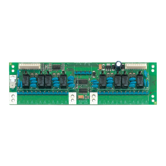
An 8-way clocked relay card ATS1811 provides eight single pole relays with
connection terminals to the common (C), normally open (NO), and normally
closed (NC) contacts.
The relay contacts are rated at 1 Amp @ 0 to 30 VDC; reducing to 300 mA @
48 VDC.
Relay cards can be connected together to provide up to 16 relays when
connected to a DGP, 64 relays in a ATS1260 4-lift DGP, or 255 relays when
connected to the ATS control panel
A LED is provided for every relay to indicate activation.
W
IRING
Interconnection between the relay card and the different ATS equipment is
detailed below.
ATS 1811 Relay
x x x x
card IN
1
2
4
5
10
Interconnection between two ATS1811 relay cards
ATS 1811 Relay
y y y y
card Out
1
2
4
5
10
Nombre maximum de cartes 8 relais par dispositif ATS
Centrales
Contrôleurs (toutes versions)
Contrôleur 4 portes (ATS1250)
Contrôleur 4 ascenseurs (ATS/1260)
Remarque :
M
ODEL
ATS 3000/4000 (J8),
ATS 1250/1260 (J21), ATS 1201 (J8)
I
N
x
+ -
+ -
+ -
NO C NC NO C NC
NO C NC NO C NC
6
7
8
6
7
8
8-way clocked relay card
ATS3000/4000(J8), ATS1250/1260 (J21) OR
ATS1201 (J8)
Name
+12 V
1
Data
2
Latch
4
Clk
5
0 V
10
Connections
Name
+12 V
1
Data
2
Latch
4
Clk
5
0 V
10
Carte bus 8 relais
Nbre
Dispositif
max. de
cartes
32
2
6
8
Vous ne pouvez pas utiliser les cartes 8 relais ni les cartes
4 relais sur le même dispositif.
ATS1811
Connections
ATS1811 Relay
x x x x
cars IN
Nbre max. de
relais
utilisables
255
16
48
64
1
Publicité

Sommaire des Matières pour Aritech ATS1811
- Page 1 ELAYS ATS Control panel or Depending on the type of enclosure and the battery An 8-way clocked relay card ATS1811 provides eight single pole relays with 4-door/4-lift DGP used, the ATS1810 relay card must be mounted in connection terminals to the common (C), normally open (NO), and normally a separate enclosure and is connected with the closed (NC) contacts.
- Page 2 ELAIS ATS 1811 OUT ATS1811 IN +12 V Une carte bus 8 relais ATS1811 fournit huit relais contacts secs polarisables Data à un contact inverseur, commun (C), normalement ouvert (NO) et Latch normalement fermé (NC). Les contacts du relais ont un pouvoir de coupure de 1 Amp entre 0 et 30 VCC, qui descend à...
- Page 3 8-32 zone di connessione ai contatti comune (C), normalmente aperto (NO), e Nota: L’ATS1811 è un C.S. di formato “BB”. normalmente chiuso (NC). Questi contatti relè hanno una portata a 1 Amp da 0 a 30 Vcc; che Numero max di schede relè...
- Page 4 ATS1811 ODEL ECHNICAL PECIFICATIONS TECHNIQUES ECHNISCHE EGEVENS PECIFICHE TECNICHE Current consumption Consommation électrique Stroomverbruik Assorbimento – standby – en standby – standby – standby 50 mA. – all relays active – avec tous les relais actifs – alle relais actief.


