Table des Matières
Publicité
Les langues disponibles
Les langues disponibles
Liens rapides
Publicité
Table des Matières

Manuels Connexes pour Broan best K34


Sommaire des Matières pour Broan best K34
- Page 1 Model K34 ENGLISH..........2 FRANÇAIS........12 ESPAÑOL.........22 BEST BY BROAN P.O. Box 140 Hartford, WI 53027...
- Page 2 READ AND SAVE THESE INSTRUCTIONS INTENDED FOR DOMESTIC COOKING ONLY WARNING TO REDUCE THE RISK OF FIRE, ELECTRIC SHOCK, OR INJURY TO PERSONS, OBSERVE THE FOLLOWING: 1. Use this unit only in the manner intended by the manufacturer. If you have questions, contact the manufacturer at the address or telephone number listed in the warranty.
- Page 3 CAUTION 1. To reduce risk of fire and to properly exhaust air, be sure to duct air outside. Do not vent exhaust air into spaces within walls or ceilings or into attics, crawl spaces, or garages. 2. Take care when using cleaning agents or detergents. 3.
-
Page 4: Prepare The Hood
PREPARE THE HOOD Unpack hood and check contents. You should receive: SUPPORT RODS 1 - Hood 1 - Decorative Flue Assembly 1 - Parts Bag (B080810533) containing: 1 - Duct Connector 1 - Flue Mounting Bracket 2 - Mounting Brackets 8 - Mounting Screws (4,8 x 38mm Pan Head) DUCTFREE PLENUM 11 - Mounting Screws (3,9 x 9,5mm Pan Head) - Page 5 INSTALL THE DUCTWORK ROOF CAP NOTE: To reduce the risk of fire, use only 6” ROUND DUCT metal ductwork. 1. Decide where the ductwork will run between the hood and the outside. 2. A straight, short duct run will allow the hood WALL DECORATIVE to perform most efficiently.
-
Page 6: Install The Hood
INSTALL THE HOOD MOUNTING SCREWS RECTANGULAR 1. Hang the hood from the brackets through CUTOUTS (4.8x38mm) the rectangular cut-outs on the back of the hood. Cut-outs are larger than the brackets MOUNTING to allow for horizontal adjustment. BRACKETS The bottom of the hood should be 24" to 30" above the cooking surface. -
Page 7: Connect Ductwork
CONNECT DUCTWORK FLUE MOUNTING BRACKET Ducted Configuration 1. Use screws (4.8x38mm) and wall anchors (supplied) to secure flue mounting bracket to the ceiling or wall as shown. 2. Use 6" round metal duct to connect the duct collar on the hood to the ductwork above. FASTEN 3. - Page 8 ;;;;; CONNECT DUCTWORK UPPER FLUE MOUNTING FLUE SECTION BRACKET VENTS Ductfree Configuration (in upper flue section) 1. Use screws and wall anchors DUCTFREE (supplied) to secure the flue PLENUM mounting bracket to wall or ceiling as shown. DUCT CONNECTOR 2. Turn upper flue section upside MEASURE OF THE down so air vents are at the top.
- Page 9 MAINTENANCE Proper maintenance of the Range Hood will assure proper performance of the unit. Grease Filters The grease filters should be cleaned fre- quently. Use a warm detergent solution. Grease filters are dishwasher safe. GREASE FILTERS To take off the grease filters: at the handle, push the stop inwards and pull the filters downwards.
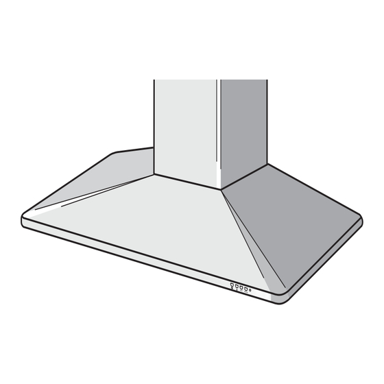
- Page 10 OPERATION BLOWER LIGHT MEDIUM SWITCH SPEED Controls BLOWER BLOWER The hood is operated using the (4) push-but- HIGH ON-LOW / tons located at eye-level, on the front edge of SPEED the hood. PILOT SWITCH LAMP The light switch turns the halogen lights on and off.
-
Page 11: Fuse Replacement
OR IMPLIED, INCLUDING, BUT NOT LIMITED TO, IMPLIED WARRANTIES OR MERCHANT ABILITY OR FITNESS FOR A PARTICULAR PURPOSE. During this one-year period, Broan will, at its option, repair or replace, without charge, any product or part which is found to be defective under normal use and service. -
Page 12: Avertissements
LISEZ ET CONSERVEZ CES INSTRUCTIONS SEULEMENT POUR UTILISATION DOMESTIQUE AVERTISSEMENTS POUR REDUIRE LES RISQUES D’INCENDIE, DE DECHARGES ELECTRIQUES OU DE DOMMAGES AUX PERSONNES, OBSERVEZ LES INSTRUCTIONS SUIVANTES: 1. N’utilisez cet appareil que comme cela est indiqué par le constructeur. Si vous avez des problèmes, contactez le fabriquant à... - Page 13 4. Utilisez un extincteur SEULEMENT si: A. Vous savez que vous avez un extincteur Classe ABC, et vous en connaissez déjà le mode d’emploi. B. Ce n’est pas un très gros incendie et qu’il se limite à l’endroi où il a explosé. C.
- Page 14 PREPAREZ LA HOTTE Enlever la hotte dans l’emballage et controller le contenu. TRINGLES Vous devez recevoir : DE SUPPORT 1 - Hotte 1 - Conduit décoratif 1 - Sachet (B080810533) avec: 1 - Raccord de conduit 1 - Étrier de support 2 - Étriers d’assemblage 8 - Vis d’assemblage (4,8 x 38mm Tête ronde) DEFLECTEUR...
-
Page 15: Installation Du Systeme D'evacuation
INSTALLATION DU SYSTEME COUVERCLE DU TOIT D’EVACUATION TUYAU ROND DE 6” REMARQUE: Pour réduire les risques d’incendie, n’utilisez que des tuyaux en métal. 1. Décidez où le tuyau doit être installé, entre CONDUIT DÉCORATIF COUVERCLE votre hotte et l’extérieur. DU MUR 2. -
Page 16: Installation De La Hotte
INSTALLATION DE LA HOTTE TROUS VIS D’ASSEMBLAGE RECTANGULAIRES (4.8x38mm) 1. Accrochez votre hotte aux étriers par les trous rectangulaires qui se trouvent ETRIERS derrière votre hotte. Les trous sont plus D’ASSEMBLAGE grands que les étriers afin de vous permettre d’ajuster tout horizontalement. -
Page 17: Connexion Du Systeme D'evacuation
CONNEXION DU SYSTEME ETRIER DE SUPPORT DU CONDUIT D’EVACUATION Modèle avec tuyau d’évacuation 1. Fixez l’étrier de support du conduit au plafond ou au mur au moyen des vis (4.8x38mm) et des chevilles (fournies) comme cela est indiqué. 2. Reliez le collier du tuyau qui se trouve sur votre hotte au système de conduction qui se trouve au-dessus au moyen d’un tuyau FIXEZ LE... -
Page 18: Installation Du Filtre Version Recyclant L'air
;;;;; CONNEXION DU SYSTEME EVACUATION DE SECTION DU ETRIER DE L’AIR (section du HAUT DU SUPPORT D’EVACUATION haut du conduit) CONDUIT Modèle recyclant l’air DEFLECTEUR 1. Attachez l’étrier de support au mur ou au plafond, comme cela est COLLIER DU indiqué, au moyen des vis et des DEFLECTEUR MESURE... -
Page 19: Entretien
ENTRETIEN Un bon entretien de votre hotte garantira une excellente performance. Filtres anti-graisse Les filtres anti-graisse doivent être nettoyés fréquemment. Utilisez une solution contenant un détergent tiède. Les filtres anti-graisse peuvent être lavés au lave-vaisselle. Pour FILTRES ANTI-GRAISSE enlever les filtres anti-graisse: à l'aide de la poignée, pousser l’arrêt vers l’intérieur et tirer le filtre vers le bas. -
Page 20: Fonctionnement
FONCTIONNEMENT BOUTON VENTILATEUR LUMIÈRE VITESSE MOYENNE Commandes VENTILATEUR Votre hotte fonctionne grâce à (4) boutons sur BOUTON VITESSE ÉLEVÉE lesquels vous devez appuyer et qui se trouvent VENTILATEUR à la hauteur de vos yeux, sur le bord antérieur VOYANT ON-bas/OFF LUMINEUX de votre hotte. -
Page 21: Remplacement Fusible
Cette garantie ne couvre pas (a) l’entretien normal ni (b) tout article ou toute pièce qui aient subi une utilisation erronée, une négligence, un accident, un entretien erroné ou une réparation (autre que de la part de Broan), une installation défectueuse ou bien une installation ne respectant pas les instructions d’installation recommandées. - Page 22 LEA Y CONSERVE ESTAS INSTRUCCIONES INDICADO PARA EL USO EN COCINAS DOMESTICAS ADVERTENCIA PARA EVITAR EL RIESGO DE INCENDIO, CORTOCIRCUITO O DAÑO PARA LAS PERSONAS, OBSERVE ATENTAMENTE LAS SIGUIENTES NORMAS: 1. Use esta unidad solamente de la manera indicada por el fabricante; si tiene dudas, póngase en contacto con éste a la dirección o teléfono indicados en la garantía.
- Page 23 ADVERTENCIA 1. Para reducir el riesgo de incendios y para evacuar correctamente los humos, asegurarse de haber realizado una conducción del aire hasta el exterior. No expulsar los humos en espacios cerrados por paredes o techos, áticos, espacios angostos o garajes. 2.
-
Page 24: Prepare La Campana
PREPARE LA CAMPANA Sacar la campana de l’embalaje y controlar el contenido. Recivireis: BARRAS DE 1 - Campana SUJECIÓN 1 - Tubo decorativo 1 - Bolsita (B080810533) con: 1 - Collar del conducto 1 - Soporte para el montaje del tubo 2 - Soportes de montaje 8 - Tornillos de montaje (4,8 x 38mm cabeza redonda) - Page 25 INSTALACION DEL TUBO DE CUBIERTA DEL TEJADO EXTRACCION TUBO DE 6” DE DIÁMETRO NOTA: para evitar el riesgo de incendio, use solamente material de metal. 1. Decida donde va a colocar el tubo de extracción entre la campana y la parte TAPA TUBO exterior.
-
Page 26: Instalacion Electrica
INSTALACION DE LA CAMPA- AGUJEROS TORNILLOS PARA RECTANGULARES MONTAJE (4.8x38mm) SOPORTES DE 1. Cuelgue la campana de los soportes por MONTAJE los agujeros rectangulares situados detrás de la campana. Los agujeros son más grandes que los soportes para permitir el ajuste en horizontal. La parte inferior de la campana debe estar a una distancia de 24”... - Page 27 ENTUBADO DE SOPORTE PARA EL MONTAJE DEL TUBO CANALIZACION Configuración con tubo 1. Use tornillos (4.8x38mm) y escarpias (adjuntas) para fijar al techo o a la pared el soporte para el montaje del tubo como se indica. 2. Use un tubo de metal de 6” de diámetro para unir el casquillo que se encuentra encima de la campana al tubo de extracción SUJETE EL...
- Page 28 ;;;;; ENTUBADO DE REJILLAS DE PARTE SOPORTE DE SALIDA DEL AIRE CANALIZACION SUPERIOR MONTAJE DEL (configuración sin DEL TUBO tubo) TUBO Configuración sin tubo 1. Use tornillos y escarpias (adjuntos) RESPIRADERO DE AIRE para asegurar el soporte de montaje del tubo a la pared o al techo como CASQUILLO se indica en la figura.
- Page 29 MANTENIMIENTO Un mantenimiento adecuado de la campana asegura el funcionamiento correcto del aparato. Filtros antigrasa Los filtros antigrasa deben limpiarse a menudo. Use un detergente que no sea fuerte. FILTROS ANTIGRASA Los filtros antigrasa se pueden meter en el lavavajillas. Para extraer los filtros antigrasa, empuje de las manillas hacia dentro y tire de los filtros hacia abajo.
- Page 30 FUNCIONAMIENTO MANDO DE INTERRUPTOR VELOCIDAD LUMINOSO MEDIA Mandos MANDO DE La campana se pone en funcionamiento MANDO DE VELOCIDAD accionando los mandos situados a la altura ENCENDIDO, MÁXIMA MÍNIMO Y de los ojos en el frontal de la campana. APAGADO El interruptor luminoso enciende y apaga las PILOTO lámparas halógenas.
- Page 31 NIENCIA PARA UN PROPOSITO ESPECIFICO. Durante el periodo de un año, Broan, si lo estima conveniente, reparará o reemplazará sin gastos para el usuario cualquier producto o parte de éste que sea defectuosos habiéndose usado correctamente. ESTA GARANTIA NO CUBRE: ESTARTER DE NEON, NEON, LÁMPARAS HALÒGENAS, LÁMPARAS DE ILUMINACIÓN.
-
Page 32: Service Parts
SERVICE PARTS MODEL K34 - Parts for stainless steel models shown. For service parts for black or white models, call Broan Customer Service. KEY NO. PART NO. DESCRIPTION B08091111 #3 Support Roads (90cm models) B08091213 #4 Support Roads (48” models) B08087163 #4 Grease Filters (48”... -
Page 33: Liste Pieces De Rechange
LISTE PIECES DE RECHANGE MODELE K34 - Ci-dessous liste pièces de rechange pour hottes en inox. Pour les pièces de recharge des modèles de couleurs noir ou blanc, contacter Broan Customer Service. PART N. DESCRIPTION B08091111 #3 Tringles de support (modèle 90cm) B08091213 #4 Tringles de support (modèle 48”) -
Page 34: Lista De Piezas De Recambio
MODELO K34 - Aquí aparecen solamente las piezas de recambio para campanas de acero inoxidable, si desean las piezas de recambio de los modelos en blanco ó negro, pónganse en contacto con el servicio al cliente de Broan. CÓD. N. - Page 35 SERVICE PARTS - LISTE PIECES DE RECHANGE -LISTA DE PIEZAS DE RECAMBIO MODEL K34 - 35 -...
- Page 36 04306994/4 - 36 -...