Publicité
Liens rapides
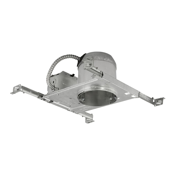
7
12
13
FIG.2
11
10
6
15
3
FIG.3
20
9
4
13
15
8584-01
16
19
17
FIG.4
16
13
23
FIG.1
11
9
24
14
16
21
22
FIG.6
WHITE SUPPLY
WHITE OR IDENTIFIED
WIRE
FIXTURE WIRE
UL LISTED
WIRENUTS
BLACK SUPPLY
PLAIN OR BLACK
WIRE
FIXTURE WIRE
BARE, OR GREEN
BARE, OR GREEN
GROUND WIRE
FIXTURE GROUND
FROM SUPPLY
WIRE
FIG.5
PAGE
4
of
4
SPEC.NO.
022177 Rev. B
8
WARNING: If any special control devices are used with this fixture, follow the instructions carefully to assure full
compliance with N.E.C. requirements. If there are any questions, contact a qualified electrical contractor.
WARNING: This product contains chemicals known to the State of California to cause cancer, birth defects, and/or other
reproductive harm. Thoroughly wash your hands after installing, handling, cleaning, or otherwise touching this product.
CAUTION: National Electrical Code, Article 110-3 (b), states that "Listed or labeled equipment shall be used or installed in
accordance with any instructions included in the listing or labeling". Use only Progress UL listed trims. Use of other trims
not listed in this fixture, including those that are UL classified, is a violation of N.E.C. 110-3 (b) and voids all warranties.
Follow this instruction sheet carefully. Be sure electricity is OFF before starting installation.
1. For Wooden Joists: Use the Centering Notches (4) located on the Plaster Frame to position the Fixture. Extend the Bar
Hangers (6), use joist alignment tabs to locate fixture and hammer the 4 Nails (7) into Joists (8) (Fig. 1). Drive additional
nails through holes in Bar Hanger for alternate support if required.
2. For Suspended Ceilings: Place the Fixture on the ceiling grid with the "T" Bars (9) running through the Bar Hanger
Notches (10). Using a flat head screwdriver or other tool, bend the integral t-bar mounting tabs (11) downward to a vertical
position (Fig. 3). Secure housing to the support structure with tie wire (supplied by others) in the holes supplied.
14
Sheetmetal screws (supplied by others) can also be used in the holes supplied (20).
3. Locate Housing along Bar Hanger in desired position and, using pliers, squeeze the 4 Locking Tabs (12) on the Plaster
Frame (13) tightly over the Bar Hangers to prevent further Housing movement. Bar Hangers (6) may be installed in
alternate Slots (23) if mounting conditions require.
4. As desired, hanger bars (6) may be shortened at score mark to fit tight mounting conditions and joist alignment tabs
removed to adjust vertically as needed by breaking off with pliers.
5. Unsnap Junction Box Cover (14) by lifting the Leaf Spring (24).
6. Run supply wires through UL Listed connectors (not supplied) in one of the five Pryouts (15) on the Junction Box (16) or
Type NM cable (ROMEX) through an Opening above the Wire Retaining Plate (17). Connect Supply Wires (19) as shown
in Fig 4 & 5. Replace Cover.
7. FOR AIR-TIGHT APPLICATIONS: This Progress product is Air-Tight approved per ASTM E283 testing standards and
complies with Washington State Energy Code Requirements. To complete the installation of this Air-Tight product, the
opening between the housing (3) and drywall ceiling (22) must be sealed by the installer using silicone caulking, tape, or
any other means acceptable to the local codes official. Progress Lighting Accessory Gasket Kit 8584-01 (purchased
separately) can be used for this purpose (Fig. 6).
8. Loosen Screws (21) to adjust Housing (3) for variations in ceiling thickness. Bottom of Housing should be flush with
ceiling (22) within tolerance.
9. Select a Trim from the Wattage Label inside the Housing. Use Only Lamp Types approved for the Trim chosen. DO
NOT EXCEED MAXIMUM LISTED WATTAGE(S)! For trim installation, refer to trim installation instructions.
INSTRUCTION SHEET MUST BE REMOVED FROM FIXTURE PRIOR TO ENERGIZING.
10-03-12
Assembly & Installation Instructions
CAUTION:
Read instructions carefully and turn electricity off at main
circuit breaker panel before beginning installation.
P84-AT
(Ceiling Opening is to be 5-1/4" in Diameter)
PAGE
1
of
4
SPEC.NO.
022177 Rev. B
10-03-12
Publicité

Manuels Connexes pour Progress Lighting P84-AT


Sommaire des Matières pour Progress Lighting P84-AT
- Page 1 (3) and drywall ceiling (22) must be sealed by the installer using silicone caulking, tape, or any other means acceptable to the local codes official. Progress Lighting Accessory Gasket Kit 8584-01 (purchased separately) can be used for this purpose (Fig. 6).
- Page 2 Se puede le Nécessaire de Joint Progress Lighting P8587-01 (acheter séparément). (Voir Fig. 2). usar el Kit de Junta Progress Lighting P8587-01 (comprar por separado). (Vea Fig. 2). FILS DE COURANT...