Publicité
Les langues disponibles
Les langues disponibles
Liens rapides
Библиотека СОК
General information:
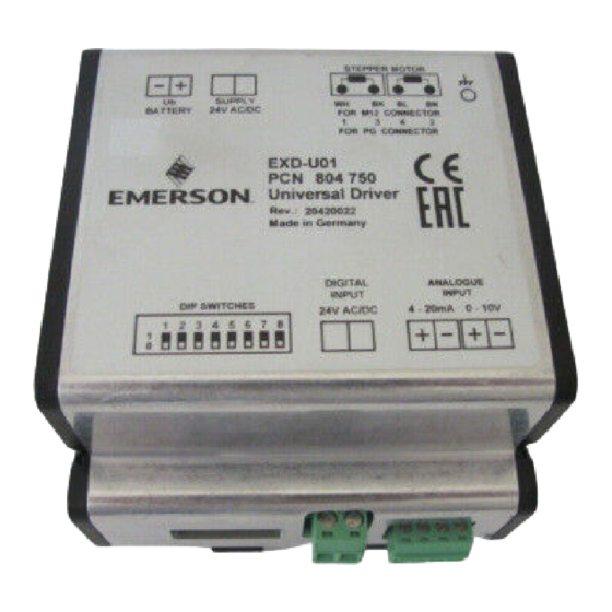
EXD-U01 Universal Driver Module is for driving Emerson stepper motor driven
electrical control valves series EX4...EX8 / CX4...CX7.
!
Safety instructions:
• Read operating instructions thoroughly. Failure to comply can result in
device failure, system damage or personal injury
• According to EN 13313 it is intended for use by persons having the
appropriate knowledge and skill.
• Before wiring disconnect all voltages from system and device.
• Do not operate system before all cable connections are completed.
• Do not apply 110/220/230V to any terminal of driver module
• Entire electrical connections have to comply with local regulations.
Installation and wiring
• Install electrical control valve in system according to operating instructions of
valve.
• Install Driver Module and other external electronic devices as shown in wiring
diagram (see Fig. 2).
• Keep separate the wires for power supply, stepper motor of valve and signal.
• Recommended wire size Ø 0.5 ... 2.5 mm
Setting (Fig.1):
• Disconnect voltage
• Set dip switches as per table below
Valve / Analog Input
EX4-6
CX4-6
EX7
CX7
EX8
4-20 mA
0-10V
Startup procedure:
• The valve must be closed before system charging in case of expansion valve or
hot gas bypass function. The valves are delivered at half open position.
Valve closure:
• Remove 24 V from digital input.
• Apply supply voltage to driver for the minimum time in below table: (valve
motor makes a characteristic sound until it reaches the closed position)
Valve
EX4-6/CX4-6
EX7/CX7/EX8
• After closure of valve evacuate the entire system.
• Then charge the system with refrigerant.
• Turn on digital input (24V)
• Start the system and check operating conditions.
Emerson Climate Technologies GmbH
Am Borsigturm 31 I 13507 Berlin I Germany
Operating Instructions
Universal Driver Module EXD-U01
for Electrical Control Valves
EX4 ... EX8 / CX4 ... CX7
2
.
Dip Switch Number
1
2
3
4
5
6
7
OFF ON ON OFF ON OFF ON
OFF ON ON OFF ON OFF OFF
ON OFF OFF ON OFF ON ON
ON OFF OFF ON OFF ON OFF
ON ON OFF ON ON ON ON
-
-
-
-
-
-
-
-
-
-
-
-
-
-
Minimum closing time [s]
2...30
6...30
www.emersonclimate.eu
Valve Synchronization:
• After power up EXD-U01 synchronizes the stepper motor driven valve with the
reference point in the fully closed position.
Technical data, power supply:
• Main supply voltage: 24 VAC ±10%, 50-60 Hz (use 1.0 A external fuse).
Note: 24 VDC supply voltage can be used but it results to lower MOPD and it
needs to be verified by system manufacture.
• Use a safety class II transformer.
Minimum power required 20 VA.
• Emergency supply voltage Ub (from ECP-024): +18 VDC.
Inputs:
• 1 analog input 4...20 mA, burden 364 Ω, or
1 analog input 0...10 V, impedance 27 kΩ.
1 digital input: 24 VAC/DC (+10%, -15%), 50-60 Hz.
Outputs:
4 current outputs for stepper motor of EX4...EX8/ CX4...CX7.
•
Uninterruptible power supply ECP-024
• Power supply voltage: 24 VAC ± 10%
• Power outputs: two, each +18 VDC
Wiring Diagram (see Fig. 2)
8
(1) = Supply voltage
-
(2) = Transformer
(3) = Fuse 1.0 A
-
(5) = Plug cable assembly EXV-Mxx for connection to EX4...EX8 / CX4...CX7
-
Cable color code
-
WH = White
-
BL = Blue
OFF
(6) = Controller supplies 4...20 mA or 0...10 V
ON
(7) = Digital input signal (0 V = OFF; 24 V = ON)
(8) = Analog input signal (4...20 mA or 0...10 V)
(9) = Optional Uninterruptible Power Supply insures the closure of valve during
power failures in systems, where a valve with positive shut-off function is
needed
• Marking:
,
Date: 07.12.2015
BK = Black
BN = Brown
EXD-U01_OI_ML_R02_865910.docx
Publicité

Sommaire des Matières pour Emerson EXD-U01
- Page 1 Valve Synchronization: EXD-U01 Universal Driver Module is for driving Emerson stepper motor driven • After power up EXD-U01 synchronizes the stepper motor driven valve with the electrical control valves series EX4…EX8 / CX4…CX7. reference point in the fully closed position.
- Page 2 Sicherheitshinweise: Ventilsynchronisation: • Lesen Sie die Betriebsanleitung gründlich. Nichtbeachtung kann zum • Beim Einschalten synchronisiert EXD-U01 das Schrittmotorventil mit dem Versagen oder zur Zerstörung des Gerätes und zu Verletzungen führen. Referenzpunkt in der vollständig geschlossenen Position. • Der Einbau darf gemäß EN 13313 nur von Fachkräften vorgenommen werden.
- Page 3 EX4 … EX8 / CX4 … CX7 Informations générales: Synchronisation de la vanne: Le module pilote universel EXD-U01 est conçu pour alimenter les vannes de • Après l’alimentation de l’EXD-U01, synchroniser la vanne avec le point de détente électroniques EX4…8/CX4…7.
- Page 4 EX4 … EX8 / CX4 … CX7 Información general: Sincronización de la válvula: El driver EXD-U01 sirve para accionar las válvulas electrónicas de motor paso a • Tras alimentar el EXD-U01 sincronice la válvula electrónica con el punto de paso de las series EX4…EX8 / CX4…CX7.
- Page 5 EX4 … EX8 / CX4 … CX7 Informazioni generali: Sincronizzazione Valvola: Il modulo driver universale EXD-U01 viene utilizzato per il funzionamento delle • Dopo aver alimentato il driver EXD-U01, sincronizzare il motore passo-passo valvole Emerson serie EX4…EX8 / CX4…CX7 azionate da motore passo-passo.
- Page 6 с шаговыми двигателями. Синхронизация клапана: Инструкция по безопасности: • После подачи напряжения питания на EXD-U01 шаговый двигатель • Внимательно прочитайте инструкцию по эксплуатации. Неисполнение синхронизируется с начальной точкой в полностью закрытом положении. инструкции может привести к отказу устройства, выходу из строя...
- Page 7 EXD-U01 Fig. 1: Fig. 2: Emerson Climate Technologies GmbH www.emersonclimate.eu Am Borsigturm 31 I 13507 Berlin I Germany Date: 07.12.2015 EXD-U01_OI_ML_R02_865910.docx...


