Publicité
Les langues disponibles
Les langues disponibles
Liens rapides
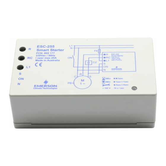
Compressor Smart Starter ES-Series
General information and technical data:
Smart Starters of the ES-Series are used to limit start current and protect
Compressors. The start current is limited to 45 Amps. Smart Starters perform a
continuous compressor monitoring by measuring voltages and currents. In case of
overvoltage, overcurrent or undervoltage the system is switched off. To protect
the compressor, restarts are delayed by 3 minutes min.
Smart starters are released for use with many compressors. (See list Fig.3)
Do not use them with Digital Scroll compressors.
ESS-255 have been shipped with faston connectors until March 2006
ESC-255 are for connection with isolated fork connectors from April 2006.
!
Safety instructions:
• Read installation instructions thoroughly. Failure to comply can result in
device failure, system damage or personal injury.
• It is intended for use by persons having the appropriate knowledge and
skill.
• Unauthorised opening of the Smart Starter will void warranty.
• Switch off all voltages / currents before cabling.
• Comply with local electrical regulations when wiring
• Do not exceed operating temperature
• Do not operate system before all cable connections are completed.
Setting:
• No setting required. The Smart Starters automatically limit the start current
based on the connected compressor size.
Mounting:
• ES Smart Starters should be mounted in electrical switch board only. Use the
mounting clip. Protect ES from direct sun light and water.
Wiring:
• Perform wiring as printed on the housing. ES Contacts:
R
Output motor run winding
RC Output run capacitor
L1 230V 50Hz power input
• Warning: Do not use an additional contactor. ES could be damaged.
• Warning: Do not connect the "RUN" capacitor C2 with the "Run" lead of the
motor. A start capacitor is built-in the Smart Starter.
• Incoming power lead (L1) and compressor run winding lead (R) should be
2
4mm
.
• Run capacitor lead can be 2.5mm
Note: The current in this lead is < 10 amps.
• For the mechanical size of the fork crimp lugs see Fig. 2.
• The fork crimp lugs must be of isolated type
• The three screws are posidrive heads (not Philips). Use a # 2 size driver.
• The screws must be tightened with 3.0... 3.5 Nm.
ESC-255
Fig. 2 Dimensions Fork Connector
Fig.3
Copeland Compressors
ZR18K4E-PFJ
ZR22K3E-PFJ
ZR34K3E-PFJ
ZR40K3E-PFJ
ZP23K3E-PFJ
ZP26K3E-PFJ
ZP41K3E-PFJ
ZH15K4E-PFJ
ZH19K4E-PFJ
ZH26K4E-PFJ
ZH30K4E-PFJ
ESC__65099.doc / 03
Operating Instructions
S
Sensor line to start winding
ON Start input (on if connected to 230V)
N
Neutral line
2
, if this complies with local regulations.
ES
ZR28K3E-PFJ
ZR48K3E-PFJ
ZP32K3E-PFJ
ZH21K4E-PFJ
replaces / ersetzt ESC__65099.doc / 02
Emerson Electric GmbH & Co. OHG
Heerstr.111 – D-71332 Waiblingen
GB
Tel.: 07151 509-0 - Fax.: -200
www.ecopeland.com/alcoliterature.cfm
• The wiring diagram per Fig.1 is an example how safetyfunctions and crankcase
heater can be wired.
C2 Run capacitor
F1
Circuit breaker of control circuit
F2
Discharge gas thermostat
F3
High pressure switch
F4
Low pressure switch
• Note: The "RC" output can be used to switch the condenser fan.
Operation
• After all connections are wired, supply voltage can be switched on. The motor
will start with limited start current, when contact "ON" is connected to 230V
(for min. 0.5 sec). The Smart Starter monitors the start sequence.
• If the motor does not start (e.g. locked rotor) it is switched-off by Smart Starter
latest after 0.8 sec. For compressor protection a restart is delayed by 5 Minutes.
• The compressor is switched-off, when "ON" is disconnected from 230V. A
restart is delayed by 3 Minutes. After this time a start is possible immediately.
• The LED is indicating following operating conditions:
Ready to accept a start command:
3 minute cycle delay:
Fault mode:
Low voltage:
Standards
• Electro magnetic compatibility
• Low voltage directive
• Safety and environmental requirements for refrigeration systems and heat
pumps
• Contactors and motor-starters - AC semiconductor motor controllers and
starters
Technical Data
Operating voltage
Continuous compressor current, max.
Compressor start current limited to max. 45 A
Signal current at "ON" input
Operating temperature
Storage temperature
Start capacitor
Start delay after stop
Vibration resistance (10 ... 1000 Hz)
Protection acc. IEC 529
Emerson Electric GmbH & Co. OHG
Heerstr.111 – D-71332 Waiblingen
Tel.: 07151 509-0 - Fax.: -200
www.ecopeland.com/alcoliterature.cfm
Fig.1
PCN 865 175
F6
Circuit breaker of motor
K1 Contactor
Q1 Main switch
R2 Crankcase heater
a double blink every 5 seconds,
1 flash per second
slow flash, 5 sec on, 5 sec off
fast flash, 10 per second
EN 55014
EN 60947-1 / EN60947-5-1
EN 378
EN60947-4-2
230 V AC +10% / -15%
25 A
~0.4mA (gold contact recommended)
-20 ... +65°C n.c.
-40 ... +85°C n.c.
200 ... 240 uF
3 Min.
4 g
IP 20
1 / 5
30.03.2006
Publicité

Manuels Connexes pour Emerson ES Serie


Sommaire des Matières pour Emerson ES Serie
- Page 1 Emerson Electric GmbH & Co. OHG Operating Instructions Heerstr.111 – D-71332 Waiblingen Compressor Smart Starter ES-Series Tel.: 07151 509-0 - Fax.: -200 www.ecopeland.com/alcoliterature.cfm General information and technical data: • The wiring diagram per Fig.1 is an example how safetyfunctions and crankcase Smart Starters of the ES-Series are used to limit start current and protect heater can be wired.
- Page 2 Emerson Electric GmbH & Co. OHG Betriebsanleitung Heerstr.111 – D-71332 Waiblingen Verdichter Smart Starter, Baureihe ES Tel.: 07151 509-0 - Fax.: -200 www.ecopeland.com/alcoliterature.cfm • Der Verdrahtungsplan in Fig.1 zeigt beispielhaft die Kombination der Beschreibung: Sicherheitsschalter mit der Kurbelgehäuseheizung. Die Smart Starter der Baureihe ES werden zur Anlaufstrombegrenzung und zum...
- Page 3 Emerson Electric GmbH & Co. OHG Instructions de service Heerstr.111 – D-71332 Waiblingen Smart Starters de la série ES Tel.: 07151 509-0 - Fax.: -200 www.ecopeland.com/alcoliterature.cfm Informations générales et caractéristiques techniques: • Le plan de cablage donné Fig.1 est un exemple type de raccordement des Les Smart Starters de la série ES limitent le courant de démarrage et protègent les...
- Page 4 Emerson Electric GmbH & Co. OHG Istruzioni di Installazione Heerstr.111 – D-71332 Waiblingen Smart Starter Serie ES Tel.: 07151 509-0 - Fax.: -200 www.ecopeland.com/alcoliterature.cfm Informazioni generali e dati tecnici: • Il diagramma in fig. 1 è un esempio di come collegare le sicurezze e la Gli Smart Starter della serie ES sono utilizzati per ridurre la corrente di resistenza carter.
- Page 5 Emerson Electric GmbH & Co. OHG Návod k montáži Heerstr.111 – D-71332 Waiblingen ES smartstartér pro jednofázové motory Tel.: 07151 509-0 - Fax.: -200 www.ecopeland.com/alcoliterature.cfm Základní údaje a technická data • Schema elektro - obr.1 je príklad správného zapojení ochran a topení maziva.