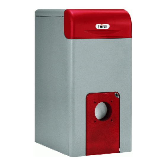
Sommaire des Matières pour Ferroli GN1
- Page 1 CHAUDIERE EN FONTE HAUT RENDEMENT, POUR LE CHAUFFAGE CENTRAL CAST IRON HIGH EFFICIENCY SECTIONAL BOILER, FOR GAS/OIL FUELS...
- Page 2 Index 1. Présentation 2. Caractéristiques dimensionnelles et techniques 3. Conditionnement 4. Installation 5. Contrôles 6. Entretien 7. Nomenclature composants...
- Page 3 1. Présentation 1.01 Introduction La chaudière GN1 est un nouveau générateur de chaleur à haut rendement, pour le chauffage. Le corps de chauffe est constitué d'éléments en fonte nipples dont le profil à été particulèrement étudié et qui permet des hautes performances thermiques et par consequence economie d'energie.
- Page 4 (PCS) (PCI) nominale (PCS) en eau Min. éléments combustion combustion gaz+fioul gaz+fioul Max. Ømm Min. Max. Max. Min. 16,4 GN1 02 28,6 25,8 23,3 18,2 15,0 260x310 16,4 GN1 03 38,7 34,9 18,2 15,0 260x310 35,4 GN1 04 57,3 51,6...
- Page 5 2.02 Données des pertes de charge (fig. 3) Les pertes de charge du circuit hydraulique par modèle de chaudière, specifiées dans le diagramme ci dessous, sont les pertes de charge du débit d'eau dans la chaudière à la puissance nominale. Fig.
- Page 6 Schéma éléctrique 230V 50Hz 230V 50Hz Fig. 5 IL = INTERRUPTEUR CA = CONTACT AUSILIAIRE TR = AQUASTAT DE REGLAGE TS = AQUASTAT DE SECURITE BRULEUR CIRCOLATEUR 11-12 = BORNES DISPONIBLES ENLEVER OU MOMENT DE CABLER LES OPTIONALS 4. Installation L'installation de la chaudière doit être effectuée par du Personnel Qualifié, suivant les instructions du fabricant et les prescriptions en vigueur.
- Page 7 4.03 Raccordement de la cheminée Il est recommandé de respecter les normes en vigueur. Le conduit entre chaudière et cheminée doit resister aux hautes temperatures et à la corrosion et doit être completement étanché. Le conduit de fumée sera éventuellement tubé en cas de condensation. 5.
- Page 8 6.01 Nettoyage de la chaudière Enlever le courant de la chaudière. Enlever les panneaux 1,2,3 (fig. 6). Proceder au nettoyage de la chaudière Contrôler que le conduit des fumées soit propre. Pour le nettoyage du brûleur suivre les instructions du Fabricant. Brosse de nettoyage Brosse de nettoyage...
- Page 9 7. Nomenclatura composants POS. CODE DESCRIPTION 37025720 FLANC GAUCHE COMPLET 14 3640178/0 BOUCHON EN PLASTIQUE 33004920 ELEMENT AVANT 35000390 BROSSE DE NETTOYAGE 37025730 FLANC GAUCHE COMPLET 33004710 ELEMENTO ARRIERE 37025740 FLANC GAUCHE COMPLET 35003370 SYSTÈME MULTIFONCTIONNEL 33004720 ELEMENT INTERMEDIAIRE 37025750 COUVERCLE COMPLET (pas fourni) 34204000...
- Page 11 Index 1. Technical informations 2. Dimensions and technical data 3. Packing and shipping details 4. Installation 5. Testing 6. Service 7. Boiler components...
- Page 12 1. Technical informations 1.01 Introduction GN1 boiler is a new heating generator with high efficiency, for central heating system as well sanitary hot water production suitable for burners using oil or gas. The boiler body is built by cast iron sections joined togheter by mean of biconical nipples and tie rods. Sections fins are especially developed to achieve the best efficiency of the boiler in order to save on fuel consumption.
- Page 13 (gross) (net) capacity output output element lenght dimension gas+oil gas+oil Max. Min. Ømm Max. Max. Min. Min. 16,4 GN1 02 28,6 25,8 23,3 18,2 15,0 260x310 16,4 GN1 03 38,7 34,9 18,2 15,0 260x310 35,4 GN1 04 57,3 51,6 46,5...
- Page 14 2.02 Pressure drop (fig. 3) Pressure drops according to the boiler size are specified on the following diagram and refer to temperature difference between flow and return comprises between 10 and 20°C. Fig. 3 3. Packing and shipment Boiler is delivered complete assembled in a wood crate. Fig.
- Page 15 N.B. - Appliance must be earthed. It is recommended to connect the boiler to a good electric earth system. FERROLI could not be considered responsable for any kind of damage to Persons or things caused by failure of earthing the system.
- Page 16 4.02 Hydraulic connections Boiler must be connected to the system according to boiler back part indications and those provided at fig. 2. Pipe must be free of any kind of strain and security valves must be provided in both central heating system and domestic hot water system location of such security valves be as close is possible to the boiler and between the boiler and valve no obstructions or gate valves must be placed.
- Page 17 5.04 Switch off To turn off the unit for a short period it is enough to switch off the switch 4 (fig. 1) on the control panel. If the boiler has to be stopped for long period beside to act by the switch 4, it is necessary to cut the supply of fuel by mean of the gate valve, in winter season, to avoid damages due to the frost it is necessary to add the antifrost liquid in the system or to drain it completely.
- Page 18 7. Boiler parts POS. CODE DESCRIPTION 15 35000390 TUBE BRUSH 29 37025720 LEFT PANEL FOR GN1 06 1 33004920 FRONT SECTION 2 33004710 REAR SECTION 16 35003370 MULTIFUNCTIONAL CONTROL 29 37025730 LEFT PANEL FOR GN1 07 3 33004720 MIDDLE SECTION...
- Page 20 37047 SAN BONIFACIO - VR - Italia Tel. 045/6139411 - Tlx. 480172 Fax 045/610233 - 6100933...


