Publicité
Les langues disponibles
Les langues disponibles
Table des Matières
160 kgf
ø 250 mm
C o p y r i g h t © 2 0 0 2 Ve t u s d e n O u d e n n . v. S c h i e d a m H o l l a n d
Installatie instructies
Installation instructions
Einbauanleitung
Instructions d'installation
Instrucciones de instalación
Istruzioni per il montaggio
NEDERLANDS
ENGLISH
DEUTSCH
FRANÇAIS
ESPAÑOL
ITALIANO
2
4
6
8
10
12
Publicité
Table des Matières

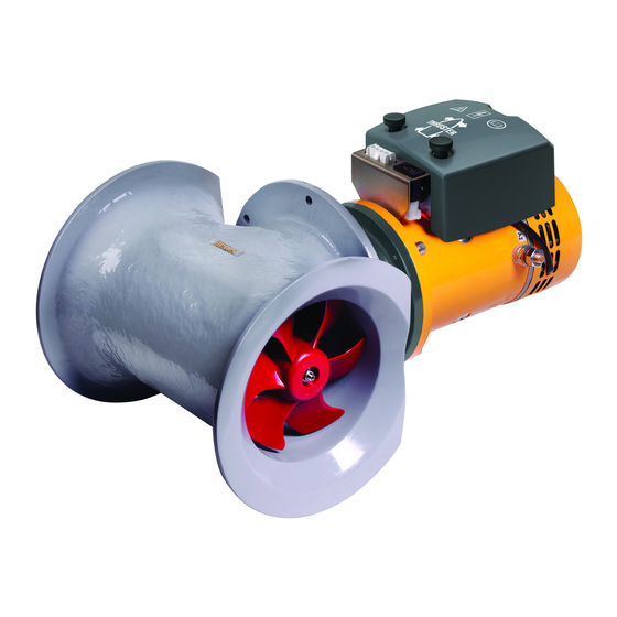
Sommaire des Matières pour Vetus STERN250P
- Page 1 Installatie instructies Installation instructions Einbauanleitung Instructions d’installation Instrucciones de instalación Istruzioni per il montaggio NEDERLANDS ENGLISH DEUTSCH FRANÇAIS ESPAÑOL ITALIANO 160 kgf ø 250 mm C o p y r i g h t © 2 0 0 2 Ve t u s d e n O u d e n n . v. S c h i e d a m H o l l a n d...
- Page 2 Opstelling van de hekschroef Bij het kiezen van de plaats waar de hekschroef wordt inge- De Vetus ‘boegschroef’ type ‘160 kgf’ kan met behulp van deze bouwd dient voor een optimaal resultaat de hartlijn van de tun- montageset (flens en de bijbehorende tunnel) eenvoudig als nelbuis tenminste 250 mm onder de waterlijn te liggen.
- Page 3 NEDERLANDS Aanbrengen van de flens Monteer de tunnel op de flens met de meegelever- Breng aan de buitenzijde, op de plaats waar de hekschroef de bouten en sluitringen. moet komen, de boormal aan en teken de gaten af. Voorzie deze bouten, M6x20, van een borgmid- De boormal bevindt zich op de...
- Page 4 Positioning of the stern thruster When choosing the location for the stern thruster take in Vetus ‘bow thruster’ of the ‘160 kgf’ model can be installed eas- account that for an optimum result the centerline of the thrust ily as a ‘stern thruster’ by using this installation set (flange and tunnel must be at least 250 mm below the the waterline.
-
Page 5: Important
ENGLISH Installation of the flange Install de thrust tunnel onto the flange with the At the place of installation of the stern thruster attach the drill supplied bolts en washers. pattern at the outside and mark the holes. Provide these bolts, M6x20, with a screwlock. - Page 6 Einführung Ausrichtung der Heckschraube Bei der Bestimmung der Stelle, an der die Heckschraube Die Vetus-‘Bugschrauben’ des Typs ‘160 kgf’ kann mit Hilfe eingebaut wird, muß die Achse des Tunnelrohres mindestens dieses Montage-Sets (Flansch und dazugehöriger Tunnel) 250 mm unter der Wasserlinie liegen, damit ein optimaler einfach als ‘Heckschraube’...
- Page 7 DEUTSCH Montage des Flansches Schließen Sie mit Hilfe der Lieferumfang Bringen Sie die Bohrschablone an der Außenseite dort an, an hörenden Schrauben und der Heckschraube installiert werden soll und zeichnen Sie die Unterlegscheiben Löcher an. Tunnel an den Flansch an. Versehen diese Die Bohrschablone befindet sich auf...
-
Page 8: Utilisation
Installation de l’hélice de poupe Pour un résultat optimum, il faudra tenir compte, lors du choix L’hélice d’étrave Vetus de type ‘160 kgf’ peut être facilement de l’emplacement où devra être montée l’hélice de poupe, du installées comme hélice de poupe grâce à ce kit de montage fait que l’axe du tunnel tubulaire doit se trouver à... - Page 11 FRANÇAIS Mise en place de la bride Monter le tunnel sur la bride à l’aide des boulons Placer le gabarit à l’extérieur, à l’endroit où doit venir l’hélice de et rondelles de blocage poupe et marquer les trous. fournis. Pourvoir ces boulons Le gabarit de forage se trouve sur la M6x20 d’un agent de blo- page du milieu.
- Page 12 Situar la hélice de popa Al determinar el lugar donde empotrar la hélice de popa con un La ’hélices de estrave’ de Vetus tipo ‘160 kgf’ se pueden insta- resultado óptimo, procúrese que el eje central del conducto lar de forma sencilla como `hélice de popa’ con ayuda de este quede por lo menos 250 mm debajo de la línea de flotación.
- Page 13 ESPAÑOL Instalación de la brida Montar el conducto en la brida con los tornillos y Situar en el lado exterior, donde se pondrá la hélice de popa, la arandelas planas suminis- plantilla y marcar los orificios. trados. Disponer en dichos tor- La plantilla de perforación se nillos M6x20 un medio encuentra en la página central.
- Page 14 Collocazione dell’elica di poppa Al momento di scegliere il punto in cui montare l’elica di poppa, L’ ‘eliche di prua’ della VETUS tipo ‘160 kgf’ puó facilmente è necessario tenere presente che, per il funzionamento ottima- essere installate come ‘eliche di poppa’, seguendo le istruzioni le, l’asse di simmetria del tunnel deve trovarsi almeno 250 mm...
- Page 15 ITALIANO Montaggio della flangia Montare il tunnel sulla flan- gia con i dadi e le rondel- All’esterno, nel punto in cui si intende collocare l’elica, segnare i punti in cui vanno praticati i fori, servendosi della sagoma di Munire questi dadi, trapanazione.
- Page 16 Hoofdafmetingen Principal dimensions Hauptabmessungen Dimensions principales Dimensiones principales Dimensioni principali 2.0535 Installation set for stern thruster ‘160 kgf’...
- Page 17 ‘160 kgf’ 1 : 5 2.0535 Installation set for stern thruster ‘160 kgf’...
- Page 18 FOKKERSTRAAT 571 - 3125 BD SCHIEDAM - HOLLAND - TEL.: +31 10 4377700 - TELEX: 23470 TELEFAX: +31 10 4372673 - 4621286 - E-MAIL: sales@vetus.nl - INTERNET: http://www.vetus.nl Printed in the Netherlands 2.0535 I.ST250 07-02...


