Table des Matières
Publicité
Les langues disponibles
Les langues disponibles
Liens rapides
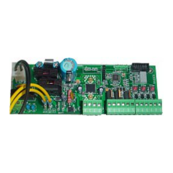
RSK24 SMT
Apparecchiatura di controllo per l'automazione di cancelli battenti
Unit for the automatic control of swing gates
Platine de commande pour l'automatisation de portails battants
Steuereinheit für Drehfl ügeltore
Equipo de control para la automatización de cancelas batientes
SCOPO DEL MANUALE
Questo manuale è stato redatto dal costruttore ed è parte integrante del prodotto.
In esso sono contenute tutte le informazioni necessarie per:
• la corretta sensibilizzazione degli installatori alle problematiche della sicurezza;
• la corretta installazione del dispositivo;
• la conoscenza approfondita del suo funzionamento e dei suoi limiti;
• il corretto uso in condizioni di sicurezza.
La costante osservanza delle indicazioni fornite in questo manuale, garantisce la sicurezza
dell'uomo, l'economia di esercizio e una più lunga durata di funzionamento del prodotto.
Al fi ne di evitare manovre errate con il rischio di incidenti, è importante leggere attentamente questo
manuale, rispettando scrupolosamente le informazioni fornite.
Le istruzioni, i disegni, le fotografi e e la documentazione contenuti nel presente manuale sono di proprietà
APRIMATIC S.p.a. e non possono essere riprodotti in alcun modo, né integralmente, né parzialmente.
Il logo "APRIMATIC" è un marchio registrato di APRIMATIC S.p.a.
ABOUT THIS MANUAL
This manual has been drafted by the manufacturer and is an integral part of the product.
The manual contains information about:
• Safety precautions for installers.
• Installation instructions.
• Detailed operating instructions.
• Using the device safely.
Follow the instructions given in this manual. This will ensure that your Aprimatic product gives
long, trouble-free service.
Follow the safety precautions and instructions given in this manual. This will ensure that your
Aprimatic product gives long, safe service.
All rights reserved. All the instructions, drawings, photos and documentation in this manual are the
property of Aprimatic S.p.a. All copying, in part or in whole, is strictly forbidden.
The "APRIMATIC" logo is a registered trade mark of APRIMATIC S.p.a.
BUT DU MANUEL
Ce manuel a été réalisé par le constructeur et fait partie intégrante du produit.
Il contient toutes les informations nécessaires pour :
• sensibiliser les installateurs aux problèmes liés à la sécurité ;
• installer le dispositif de manière correcte ;
• connaître le fonctionnement et les limites du dispositif ;
• utiliser correctement le dispositif dans des conditions de sécurité optimales.
Le respect des indications fournies dans ce manuel garantit la sécurité personnelle, une économie
de fonctionnement et une longue durée de vie du produit.
Afi n d'éviter des opérations incorrectes et de ne pas risquer des accidents sérieux, lire attentivement
ce manuel et respecter scrupuleusement les informations fournies.
Les instructions, les dessins, les photos et la documentation contenus dans ce manuel sont la
propriété de la société APRIMATIC S.p.a et ne peuvent être reproduits sous aucune forme, ni
intégralement, ni partiellement.
Le logo « APRIMATIC » est une marque enregistrée de APRIMATIC S.p.a.
ZWECK DES HANDBUCHS
Dieses Handbuch wurde vom Hersteller verfasst und ist ein ergänzender Bestandteil des Produkts.
Es enthält alle nötigen Informationen für:
• die richtige Sensibilisierung der Monteure für Fragen der Sicherheit;
• die vorschriftsmäßige Installation der Vorrichtung;
• die umfassende Kenntnis ihrer Funktionsweise und ihrer Grenzen;
• die vorschriftsmäßige und sichere Benutzung.
Die ständige Beachtung der in diesem Handbuch gelieferten Hinweise gewährleistet die Sicherheit
der Personen, wirtschaftlichen Betrieb und eine lange Lebensdauer des Produkts.
Zur Vermeidung fehlerhafter Manöver mit Unfallgefahr ist es wichtig, dieses Handbuch aufmerksam
durchzulesen und die darin enthaltenen Informationen genauestens zu beachten.
Die Anleitungen, Zeichnungen, Fotos und Dokumentationen in diesem Handbuch sind Eigentum von
APRIMATIC S.p.a. und dürfen in keiner Weise ganz oder teilweise reproduziert werden.
Das Logo „APRIMATIC" ist eine eingetragene Marke der APRIMATIC S.p.a.
OBJETO DEL MANUAL
Este manual ha sido redactado por el constructor y forma parte integrante del producto.
Contiene todas las informaciones necesarias para:
• la correcta sensibilización de los instaladores hacia los problemas de la seguridad;
• la correcta instalación del dispositivo;
• el conocimiento en profundidad de su funcionamiento y de sus límites;
• el correcto uso en condiciones de seguridad.
La constante observación de las indicaciones suministradas en este manual, garantiza la seguridad
del hombre, la economía del ejercicio y una mayor duración de funcionamiento del producto.
Con el fi n de evitar maniobras equivocadas con riesgo de accidente, es importante leer atentamente
este manual, respetando escrupulosamente las informaciones suministradas.
Las instrucciones, los dibujos, las fotografías y la documentación que contiene este manual son
propiedad de APRIMATIC S.p.a. y no pueden ser reproducidas en ninguna manera, ni integral
ni parcialmente.
El logotipo "APRIMATIC" es una marca registrada de APRIMATIC S.p.a.
Istruzioni per Installazione,
Uso e Manutenzione
Installation, use and maintenance
Notice d'installation,
usage et entretien
Anleitung für Montage, Gebrauch
Instrucciones para la instalación
uso y mantenimiento
instructions
und Wartung
Publicité
Chapitres
Table des Matières

Manuels Connexes pour Aprimatic RSK24 SMT


Sommaire des Matières pour Aprimatic RSK24 SMT
- Page 1 • Detailed operating instructions. • Using the device safely. Follow the instructions given in this manual. This will ensure that your Aprimatic product gives long, trouble-free service. Follow the safety precautions and instructions given in this manual. This will ensure that your Aprimatic product gives long, safe service.
-
Page 2: Table Des Matières
Sommario / Premessa Premessa e Norme di sicurezza ....................2-3 Descrizione del prodotto Descrizione del prodotto ........................3 Uso previsto e campo d’impiego ......................3 Dati tecnici ............................3 Installazione elettrica e messa in funzione ................4 Predisposizione impianto elettrico ....................4 Collegamenti elettrici ........................4 Allacciamento alla tensione di rete ....................4 Schema dell’apparecchiatura e collegamenti ...................5 Avvio del sistema... -
Page 3: Descrizione Del Prodotto
• È vietato lasciare incustodita la zona di lavoro. DESCRIZIONE DEL PRODOTTO RSK24 SMT - apparecchiatura dotata di microprocessore per l’azionamento di uno o due motori fi no a 250 Watt di potenza massima complessiva. Può essere fornita col modulo radioricevente già innestato a bordo. -
Page 4: Installazione Elettrica E Messa In Funzione
Installazione elettrica e messa in funzione INSTALLAZIONE ELETTRICA E MESSA IN FUNZIONE L’installazione elettrica deve essere effettuata al termine dell’installazione meccanica. Per garantire la corretta MESSA in FUNZIONE del SISTEMA la sequenza da rispettare è la seguente: PREDISPOSIZIONE IMPIANTO ELETTRICO (par. 2.1) COLLEGAMENTI ELETTRICI (par. -
Page 5: Schema Dell'apparecchiatura E Collegamenti
J4 connettore collegamento 230 VAC M1 collegamento fase-terra-neutro 230 VAC FS1-2 collegamento 24 VAC CN1 connettore 3 pin Aprimatic per innesto accessori (ricevente Unico, decoder controllo accessi, ecc.) CN2 connettore 10 pin per ricevente PL-ECO FS3-4 BATT collegamento batterie 24 VDC... -
Page 6: Avvio Del Sistema: Ciclio Di Autoapprendimento
Avvio del sistema / Autoapprendimento AVVIO DEL SISTEMA: Fig.4 CICLO DI AUTOAPPRENDIMENTO Autoapprendimento Al termine dei collegamenti, è assolutamente giallo blu cancello chiuso indispensabile far eseguire un ciclo di autoapprendimento per la messa in funzione del sistema. Se la procedura di autoapprendimento non viene portata a termine l’automazione non può... -
Page 7: Memorizzazione Dei Telecomandi
Memorizzazione telecomandi / Prove di funzionamento e regolazioni MEMORIZZAZIONE DEI TELECOMANDI Fig.5 Per il riconoscimento dei telecomandi seguire la procedura del par.3.2A o 3.2B in base alla ricevente installata. Al termine delle memorizzazioni il tasto 1 comanda lo START e il tasto 2 lo START PEDONALE (Fig.5). 3.2A CON RICEVENTE BICANALE A INNESTO PL-ECO (Fig.6) Attivare l'apprendimento Fig.6... -
Page 8: Programmazione Avanzata
Programmazione avanzata PROGRAMMAZIONE AVANZATA PROGRAMMAZIONE DEI PARAMETRI IMPORTANTE! Effettuare la programmazione dei parametri solo con il cancello CHIUSO e FERMO e dopo aver effettuato l’AUTOAPPRENDIMENTO. Per la programmazione dei parametri procedere come di seguito descritto con riferimento a fi g.7 e a tab.2. Attenzione In fase di programmazione i segnali in ingresso vengono ignorati. -
Page 9: Reset
Reset - Logiche di funzionamento RESET Se si desidera ripristinare tutti i parametri programmabili ai valori di fabbrica (default) occorre effettuare il RESET: Togliere tensione; Premere e mantenere premuto il tasto BLU e contemporaneamente ripristinare la tensione sul display viene visualizzata la lettera S lampeggiante: è... -
Page 10: Logiche Di Funzionamento
Logiche di funzionamento 0 - LOGICA AUTOMATICA impulso/segnale START STOP sicurezza in chius. costa sensibile in ap. fotocellula in apert. ostacolo chiusa apre blocca aperta blocca blocca blocca in chiusura riapre blocca riapre blocca riapre in apertura blocca inverte e blocca blocca inverte e blocca bloccata in chiusura da STOP chiude... -
Page 11: Funzionalità Del Sistema Di Controllo
Funzionalità del sistema di controllo FUNZIONALITÀ DEL SISTEMA DI CONTROLLO GESTIONE DEI MOTORI RSK24 SMT dispone di uscite indipendenti per i motori. Quando viene collegato il solo Motore1 (applicazione in versione monoanta) il sistema di controllo regola automaticamente il funzionamento opportuno. -
Page 12: Funzionamento In Sicurezza
Funzionalità del sistema di controllo interrompendo e liberando il fascio delle fotocellule con le ante aperte, l’automazione effettua 3 sec. di prelampeggio (se abilitato da parametro F) e quindi la chiusura anche se il tempo di pausa non è terminato. Col parametro in No, la chiusura avverrà... -
Page 13: Manutenzione Programmata
Verificare l’efficienza delle batterie ... ogni 6 mesi punti vendita delle batterie stesse. dei telecomandi ed eventualmente La manutenzione consigliata da Aprimatic S.p.A. per l’impianto sostituirle. elettrico è elencata in tab.4. Eliminare eventuali ostacoli interposti ... ogni 6 mesi che oscurino permanentemente il raggio delle fotocellule (es: rami o cespugli). -
Page 14: Introduction And Safety Precautions
Contents / Introduction Introduction and safety precautions..................14-15 Product description Product description .........................15 Permitted uses and applications ....................15 Technical data ..........................15 Electrical installation and connecting up ................16 Fitting electrical equipment ......................16 Connecting up ..........................16 Connecting up to the mains power supply ..................16 Layout diagram and connections ....................17 System start-up System start up: self-teach cycle ....................18... -
Page 15: Product Description
• Ensure that someone is present in the work area at all times. Do not leave the area and equipment unattended. PRODUCT DESCRIPTION RSK24 SMT - microprocessor unit for driving one or two motors with total maximum power rating of 250 Watt. It can be supplied with a radio receiver already plugged into the board. -
Page 16: Electrical Installation And Connecting Up
Electrical installation and connecting up ELECTRICAL INSTALLATION AND CONNECTING UP Complete all mechanical installation before you start the installation of electrical components and connecting up. Installation consists of the following steps: FITTING ELECTRICAL EQUIPMENT (sect. 2.1). CONNECTING UP (sect. 2.2 and 2.4). CONNECTING UP TO 230V MAINS POWER SUPPLY (sect. -
Page 17: Electrical Connections
J4 connector for 230 V AC connection. M1 230 V AC phase-earth-neutral connection. FS1-2 24 V AC connection. CN1 3-pin Aprimatic connector for accessories ( UNICO receiver, access control decoder, etc.). CN2 10-pin connector for PL-ECO receiver. FS3-4 BATT 24 V DC battery connection. -
Page 18: System Start-Up
System start-up / Self-teach SYSTEM START-UP: SELF-TEACH CYCLE Fig. 4 When all the connections have been completed you Self-teach must run the self-teach cycle before putting the system into service. Gate closed yellow blue If you do not complete the self-teach cycle, the automation will not work. -
Page 19: Programming Remote Controls
Remote control programming / Functional tests and adjustments PROGRAMMING REMOTE CONTROLS Fig. 5 To program the remote controls so that they are recognised by the system, follow the procedure in sect. 3.2A or 32B depending on the type of receiver installed. -
Page 20: Advanced Programming
Advanced programming ADVANCED PROGRAMMING PROGRAMMING PARAMETERS IMPORTANT! Before you start programming parameters, make sure that the gate is CLOSED and STOPPED and that the SELF-TEACH procedure has been completed. To program the parameters, follow the instructions given in Fig. 7 and Tab. 2 below. Warning All input signals will be ignored during programming. -
Page 21: Reset Procedure
Reset - Functioning logic RESET If you want to return all the programmed parameters to their default settings, you should RESET the unit as follows: Switch off the power supply. Press and hold down the BLUE button and at the same time switch the power supply back on again. The letter S will appear fl... - Page 22 Operating modes 0 - AUTOMATIC MODE pulse/signal START STOP closing safety opening safety edge opening photocell obstacle detection closed open lock opened lock lock lock closing reopen lock reopen lock reopen opening lock reverse and lock lock reverse and lock locked by STOP while closing close locked by STOP while opening close 1 - 4-STEP...
-
Page 23: Control System Functions
Control system functions CONTROL SYSTEM FUNCTIONS MOTOR MANAGEMENT The RSK24 SMT has separate outputs for motor control. When Motor 1 (single-wing version) only is connected, the control system will automatically control this motor. On the opening stroke, Motor 2 has a fi xed delay of 3 seconds. -
Page 24: Safety Function
Control system functions facilitate release. Pause time photocell - with this parameter set to Yes, the automation will ignore the pause time; with the wings open, covering and uncovering the photocell beam will have the effect of operating prefl ashing for 3 seconds (if the parameter F is enabled) and will start closing even if the pause time has not been fi... -
Page 25: Maintenance
... every 6 provided at sales outlets. trol batteries. Change spent batteries. months The maintenance operations recommended by Aprimatic S.p.A. for the electrical equipment is listed in Tab. 4. Remove branches, bushes or other ... every 6 obstacles which might be permanently months blocking the photocell beam. - Page 26 Table des matières / Introduction Introduction et Normes de sécurité ..................26-27 Description du produit Description du produit ........................27 Utilisation prévue et domaine d’utilisation ..................27 Caractéristiques techniques ......................27 Montage électrique et mise en service ..................28 Prédisposition SYSTÈME électrique ....................28 Raccordements électriques ......................28 Raccordement à...
-
Page 27: Description Du Produit
• Ne jamais laisser la zone de travail sans surveillance. DESCRIPTION DU PRODUIT RSK24 SMT - platine équipée d’un microprocesseur pour l’actionnement d’un ou de deux moteurs jusqu’à 250 Watts de puissance totale maximum. Elle peut être fournie avec le module radiorécepteur déjà intégré. -
Page 28: Montage Électrique Et Mise En Service
Montage électrique et mise en service MONTAGE ÉLECTRIQUE ET MISE EN SERVICE Le montage électrique doit s’effectuer après le montage mécanique. Respecter la séquence de montage ci-après pour garantir une MISE en SERVICE correcte du SYSTÈME : PRÉDISPOSITION SYSTÈME ÉLECTRIQUE (par. 21). RACCORDEMENTS ÉLECTRIQUES (par. -
Page 29: Raccordement Électriques
J4 connecteur connexion 230 VAC M1 connexion phase-terre-neutre 230 VAC FS1-2 connexion 24 VAC CN1 connecteur 3 broches Aprimatic pour enfi chage accessoires (récepteur Unico, décodeur contrôle accès, etc.) CN2 connecteur 10 broches pour récepteur PL-ECO FS3-4 BATT connexion batteries 24 VDC F1 fusible de protection primaire transformateur F2 fusible de protection accessoires extérieurs (24VDC) -
Page 30: Démarrage Du Système / Auto-Apprentissage
Démarrage du système / Auto-apprentissage DÉMARRAGE DU SYSTÈME : Fig.4 CYCLE D’AUTO-APPRENTISSAGE Auto-apprentissage Une fois les connexions effectuées, il est indispensable jaune bleu portail fermé de lancer un cycle d’auto-apprentissage pour mettre le système en service. L’automatisme ne fonctionne pas si la procédure d’auto- apprentissage n’a pas été... -
Page 31: Mémorisation Des Télécommandes
Mémorisation des télécommandes / Essais de fonctionnement et réglages MÉMORISATION DES TÉLÉCOMMANDES Fig. 5 Pour l’identifi cation des télécommandes, suivre la procédure du par.3.2A ou 3.2B selon le récepteur utilisé. En fi n de mémorisation, le bouton 1 commande la MARCHE et le bouton 2 l’OUVERTURE PIÉTON (Fig.5). 3.2A AVEC RÉCEPTEUR À... -
Page 32: Programmation Avancée
Programmation avancée PROGRAMMATION AVANCÉE PROGRAMMATION DES PARAMÈTRES IMPORTANT ! Effectuer la programmation des paramètres uniquement avec le portail FERMÉ et ARRÊTÉ et après avoir effectué l’AUTO-APPRENTISSAGE. Pour programmer les paramètres, procéder selon les indications suivantes (voir fi g.7 et tab.2). Attention Les signaux d’entrée ne sont pas pris en considération en phase de programmation. -
Page 33: Remise À Zéro
Remise à zéro - Modes de fonctionnement REMISE À ZÉRO Pour rétablir les valeurs d’usine (par défaut) pour tous les paramètres programmables, effectuer une REMISE À ZÉRO : Couper la tension ; Presser et maintenir enfoncé le bouton BLEU et rétablir en même temps la tension la lettre S clignotante apparaît sur l’affi... -
Page 34: Modes De Fonctionnement
Modes de fonctionnement 0 - MODE AUTOMATIQUE impulsion/signal MARCHE ARRÊT sécurité en phase de ferm. bord sensible en phase d’ouv. cellule photoélec. en phase d’ouv. obstacle ouvre verrouille fermé verrouille verrouille verrouille ouvert rouvre verrouille rouvre2 verrouille rouvre en phase de fermeture verrouille inverse et verrouille verrouille... -
Page 35: Fonctions Du Système De Commande
Fonctions du système de commande FONCTIONS DU SYSTÈME DE COMMANDE GESTION DES MOTEURS RSK24 SMT dispose de sorties indépendantes pour les moteurs. Lorsqu’un seul Moteur1 est relié (application pour version à un vantail), le système de commande règle automatiquement le fonctionnement approprié. -
Page 36: Fonctionnement En Toute Sécurité
Fonctions du système de commande fermeture, les moteurs sont actionnés dans le sens inverse, pendant une courte période de temps, afi n de soulager la charge sur les vantaux et de faciliter le déverrouillage. Cellules photoélectriques dans le temps de pause - si le paramètre est sur Oui, l’interception et la libération des cellules photoélectriques avec les vantaux ouverts entraînent un préclignotement de 3 s (si activé... -
Page 37: Entretien
à cet effet dans les points de vente. saire. L’entretien que la société Aprimatic S.p.A. recommande pour Contrôler le fonctionnement des batter- ... tous les le système électrique est indiqué au tab.4. - Page 38 Inhaltsangabe / Vorwort Einleitung und Sicherheitsvorschriften ................38-39 Beschreibung des Produkts Beschreibung des Produkts ......................39 Bestimmungsgemäße Verwendung und Einsatzbereich ..............39 Technische Daten .........................39 Elektrische Installation und Inbetriebnahme ................40 Vorbereitung der Elektroausrüstung ....................40 Elektrische Anschlüsse ........................40 Anschluss an die Netzspannung ....................40 Plan der Steuereinheit und Anschlüsse ..................41 Start des Systems Start des Systems: Selbstlernzyklus ....................42...
-
Page 39: Sicherheitsvorschriften
• Lassen Sie den Arbeitsbereich niemals unbewacht. BESCHREIBUNG DES PRODUKTS RSK24 SMT - Steuerung mit Mikroprozessor für einen oder zwei Motoren mit einer max. Leistung von insgesamt 250 Watt. RSK24 SMT kann die Steuerung mit bereits eingestecktem Funkempfängermodul geliefert werden. -
Page 40: Elektrische Installation Und Inbetriebnahme
Elektrische Installation und Inbetriebnahme ELEKTRISCHE INSTALLATION UND INBETRIEBNAHME Die elektrische Installation muss nach Abschluss der mechanischen Installation ausgeführt werden. Zur Gewährleistung einer korrekten INBETRIEBNAHME des SYSTEMS ist die folgende Reihenfolge einzuhalten: VORBEREITUNG DER ELEKTROAUSRÜSTUNG (Abschnitt 21) ELEKTRISCHE ANSCHLÜSSE (Abschnitt 2.2 und 2.4). ANSCHLUSS AN DIE 230V NETZSPANNUNG (Abschnitt 2.3). -
Page 41: Plan Der Steuereinheit Und Anschlüsse
J4 Steckverbinder 230V WS M1 Anschluss Phase-Erdung-Neutralleiter 230V WS FS1-2 Anschluss 20V WS CN1 Aprimatic 3-Pin-Steckverbinder für Zubehör (Empfänger Unico, Decoder für Zugangskontrolle etc.) CN2 10-Pin-Steckverbinder für Empfänger PL-ECO FS3-4 BATT Batterieanschluss 24V GS F1 Sicherung zum Schutz der Primärwicklung des Transformators F2 Sicherung zum Schutz des externen Zubehörs (24V GS) -
Page 42: Start Des Systems
Start des Systems / Selbstlernfunktion START DES SYSTEMS: SELBSTLERNZYKLUS Abb. 4 Nach den Anschlüssen und zur Inbetriebnahme des Systems Selbstlernfunktion ist in jedem Fall ein Selbstlernzyklus auszuführen. Wird der Selbstlernzyklus nicht vollständig durchge- Geschlossenes Tor Gelb Blau führt, ist die Automatik nicht funktionsfähig. Während des Selbstlernzyklus erfasst die Steuerung die Daten des Systems, die der Einstellung des korrekten Betriebs dienen:... -
Page 43: Speichern Der Handsender
Speichern der Handsender / Funktionsprüfungen und Einstellungen SPEICHERN DER HANDSENDER Abb. 5 Für die Erkennung der Handsender ist je nach installiertem Empfänger gemäß der Beschreibung in Abschnitt 3.2A oder 3.2B zu verfahren. Nach dem Speichervorgang steht Ihnen Taste 1 für den START-Befehl und Taste 2 für die Funktion START FUSSGÄNGER zur Verfügung (Abb. -
Page 44: Erweiterte Programmierung
Erweiterte Programmierung ERWEITERTE PROGRAMMIERUNG PROGRAMMIERUNG DER PARAMETER WICHTIG! Die Parameter dürfen nur bei GESCHLOSSENEM und STILLSTEHENDEM Tor und erst nach Ausführung des SELBSTLERNVORGANGS programmiert werden. Für die Programmierung der Parameter gehen Sie gemäß der folgenden Beschreibung und mit Bezug auf und Tab.2 vor. -
Page 45: Reset
Reset - Betriebsarten RESET Wenn Sie sämtliche Parameter erneut auf die werkseitig eingestellten Werte (Standardeinstellung) einstellen möchten, ist ein RESET erforderlich: Unterbrechen Sie die Spannungsversorgung. Drücken Sie die BLAUE Taste, halten Sie sie gedrückt und stellen Sie gleichzeitig die Spannungsversorgung wieder her. -
Page 46: Betriebsarten
Betriebsarten Impuls/Signal AUTOMATIK Sicherheitseinrichtung Sicherheitskontaktleiste Lichtschranke START STOPP Hindernis beim Schließen beim Öffnen beim Öffnen geschlossen öffnet stoppt offen stoppt stoppt stoppt beim Schließen öffnet erneut stoppt öffnet erneut stoppt öffnet erneut beim Öffnen stoppt kehrt Richtung um und stoppt stoppt kehrt Richtung um und stoppt beim Schließen durch... -
Page 47: Funktionen Des Steuersystems
Funktionen des Steuersystems FUNKTIONEN DES STEUERSYSTEMS STEUERUNG DER MOTOREN RSK24 SMT verfügt über unabhängige Motorausgänge. Wenn nur Motor1 angeschlossen wird (bei einfl ügeligen Toren), stellt das Steuersystem automatisch die passende Betriebsart ein. Beim Öffnen hat Motor2 eine feste Verzögerung von 3 Sekunden. -
Page 48: Sicherheitsbetrieb
Funktionen des Steuersystems Schließen der Torfl ügel werden die Motoren für kurze Zeit in die umgekehrte Richtung gesteuert, um die Torfl ügel zu entlasten und die Entriegelung zu erleichtern. Lichtschranke während der Pausenzeit - Wenn der Parameter auf Ja eingestellt ist, löst die Automatik bei Unterbrechung und Freigabe des Lichtstrahls der Lichtschranken bei geöffneten Torfl... -
Page 49: Hinweise Für Den Wartungstechniker
Behältern in den gegebenenfalls aus. Verkaufsstellen der Batterien. Überprüfen Sie die korrekte Funktionsweise ... alle 6 Die von Aprimatic S.p.A. für die Elektroanlage empfohlene der Handsenderbatterien und wechseln Sie Monate Wartung ist in Tab. 4 beschrieben. sie gegebenenfalls aus. - Page 50 Índice / Introducción Introducción y normas de seguridad ..................50-51 Descripción del producto Descripción del producto .......................51 Uso previsto y campo de aplicación ....................51 Datos técnicos ..........................51 Instalación eléctrica y puesta en funcionamiento ..............52 Preparación de la instalación eléctrica ...................52 Conexiones eléctricas ........................52 Conexión de la tensión de red ......................52 Esquema del equipo y conexiones ....................53...
-
Page 51: Características Del Equipo
• Está prohibido dejar el área de trabajo sin vigilancia. DESCRIPCIÓN DEL PRODUCTO RSK24 SMT - equipo provisto de microprocesador para el accionamiento de uno o dos motores de hasta 250 vatios de potencia máxima global. El equipo puede suministrarse con el módulo receptor de radio ya instalado. -
Page 52: Instalación Eléctrica Y Puesta En Funcionamiento
Instalación eléctrica y puesta en funcionamiento INSTALACIÓN ELÉCTRICA Y PUESTA EN FUNCIONAMIENTO La instalación eléctrica se llevará a cabo después de la instalación mecánica. Para asegurar la correcta PUESTA EN FUNCIONAMIENTO del SISTEMA cabe atenerse a la siguiente secuencia: PREPARACIÓN DE LA INSTALACIÓN ELÉCTRICA (párr. 2.1) CONEXIONES ELÉCTRICAS (párr. -
Page 53: Esquema Del Equipo Y Conexiones
J4 conector conexión 230 VAC M1 conexión fase-tierra-neutro 230 VAC FS1-2 conexión 24 VAC CN1 conector 3 pines Aprimatic para conexión accesorios (receptor Unico, descodifi cador control accesos, etc.) CN2 conector 10 pines para receptor PL-ECO FS3-4 BATT conexión baterías 24 VDC F1 fusible de protección primario transformador... -
Page 54: Puesta En Marcha Del Sistema: Ciclo De Autoaprendizaje
Puesta en marcha del sistema / Autoaprendizaje PUESTA EN MARCHA DEL SISTEMA: Fig.4 CICLO DE AUTOAPRENDIZAJE Autoaprendizaje Realizadas las conexiones, es absolutamente indispensa- amarillo azul cancela cerrada ble realizar un ciclo de autoaprendizaje para la puesta en funcionamiento del sistema. Si el procedimiento de autoaprendizaje no llega a buen fi... -
Page 55: Memorización De Los Mandos A Distancia
Memorización de los mandos a distancia / Pruebas de funcionamiento y ajustes MEMORIZACIÓN DE LOS MANDOS A DISTANCIA Fig.5 Para el reconocimiento de los mandos a distancia, seguir el procedimiento del párr.3.2A o 3.2B dependiendo del receptor instalado. Al fi nal de las memorizaciones la tecla 1 comanda el START y la tecla 2 el START PEATONAL (Fig.5). -
Page 56: Programación De Los Parámetros
Programación avanzada PROGRAMACIÓN AVANZADA PROGRAMACIÓN DE LOS PARÁMETROS ¡IMPORTANTE! Efectuar la programación de los parámetros sólo con la cancela CERRADA y PARADA y después de haber efectuado el AUTOAPRENDIZAJE. Para la programación de los parámetros realizar las operaciones descritas a continuación con referencia a la fi g.7 y a la tab.2. Atención Durante la programación las señales en entrada se ignoran. -
Page 57: Reset
Reset - Lógicas de funcionamiento RESET Si se desea restablecer todos los parámetros programables con los valores de fábrica (por defecto) es preciso realizar el RESET: Interrumpir la alimentación; Apretar y mantener apretada la tecla AZUL y a la vez restablecer la tensión en la pantalla se visualiza la letra S intermi- tente: es necesario efectuar el autoaprendizaje;... -
Page 58: Lógicas De Funcionamiento
Lógicas de funcionamiento 0 - LÓGICA AUTOMÁTICA impulso/señal START STOP seguridad en cierre perfi l de seguridad en apert. fotocélula en apert. obstáculo cerrada abre bloquea abierta bloquea bloquea bloquea en cierre reabre bloquea reabre bloquea reabre en apertura bloquea invierte y bloquea bloquea invierte y bloquea... -
Page 59: Funciones Del Sistema De Control
Funciones del sistema de control FUNCIONES DEL SISTEMA DE CONTROL GESTIÓN DE LOS MOTORES RSK24 SMT dispone de salidas independientes para los motores. Cuando sólo se conecta el Motor 1 (aplicación en versión hoja única) el sistema de control regula automáticamente el funcionamiento oportuno. -
Page 60: Funcionamiento En Seguridad
Funciones del sistema de control las hojas y facilitar el desbloqueo. Fotocélula en el tiempo de pausa - con el parámetro en Sí, interrumpiendo y liberando el haz de las fotocélulas con las hojas abiertas, la automatización efectúa 3 seg. de pre-destello (si está habilitado mediante el parámetro F) y luego se cierra, si bien el tiempo de pausa no haya terminado. -
Page 61: Mantenimiento
Eliminar posibles obstáculos que oscu- ... cada El mantenimiento recomendado por Aprimatic S.p.A. para rezcan permanentemente el haz de las 6 meses la instalación eléctrica se indica en la tab.4. - Page 62 Note - 62 -...
-
Page 63: Dichiarazione Di Conformità
EN 60335-1:2003; Operating conformity has been checked only on installations of 24V Aprimatic model RAIDER ONE SMT; La conformità è stata verificata limitatamente all’installazione su operatori Aprimatic a 24V modello RAIDER ONE SMT; Villafontana (BO), lì 14/03/2007 Dott. Alessandro Minelli... - Page 64 Aprimatic S.p.A. via Leonardo da Vinci, 414 40059 Villa Fontana di Medicina - Bologna - Italy tel. +39 051 6960711 - fax +39 051 6960722 info@aprimatic.com - www.aprimatic.com...