Table des Matières
Publicité
Les langues disponibles
Les langues disponibles
Liens rapides
ThunderION_UM_9752160010_NL_D_GB_F_V2_2
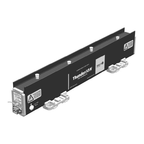
ThunderION
Static Neutralising System
NL
Gebruikershandleiding
D
Bedienungsanleitung
GB
User's Manual
F
Notice d'utilisation
SIMCO (Nederland) B.V.
Postbus 71
NL-7240 AB Lochem
Telefoon +31-(0)573-288333
Telefax
+31-(0)573-257319
E-mail
general@simco-ion.nl
Internet
http://www.simco-ion.nl
Traderegister Apeldoorn No. 08046136
1
14
27
40
Publicité
Chapitres
Table des Matières

Manuels Connexes pour ITW SIMCO ThunderION


Sommaire des Matières pour ITW SIMCO ThunderION
- Page 1 SIMCO (Nederland) B.V. Postbus 71 NL-7240 AB Lochem Telefoon +31-(0)573-288333 Telefax +31-(0)573-257319 E-mail general@simco-ion.nl Internet http://www.simco-ion.nl Traderegister Apeldoorn No. 08046136 ThunderION Static Neutralising System Gebruikershandleiding Bedienungsanleitung User's Manual Notice d'utilisation ThunderION_UM_9752160010_NL_D_GB_F_V2_2...
-
Page 2: Table Des Matières
INHOUDSOPGAVE Woord vooraf ..........................2 1. Inleiding ............................ 3 2. Veiligheid ..........................3 3. Technische specificaties ......................4 4. Installatie ..........................5 4.1. Controle vooraf ........................5 4.2. Algemeen .......................... 6 4.3. Montage ..........................6 4.4. Aansluiten .......................... 7 4.4.1. Aarding ........................7 4.4.2. -
Page 3: Woord Vooraf
GEBRUIKERSHANDLEIDING THUNDERION Woord vooraf Lees deze handleiding geheel door voordat u dit product installeert en in gebruik neemt. Instructies in deze handleiding dienen te worden opgevolgd om een goede werking van het product te waarborgen en om aanspraak te kunnen maken op garantie. Daar waar in deze handleiding wordt gesproken over staaf wordt steeds bedoeld ThunderION. -
Page 4: Inleiding
1. Inleiding De ThunderION is bedoeld om statische lading van vellen, banen en andere soortgelijke materialen te neutraliseren. De staven kunnen gebruikt worden in combinatie met een 24 V DC voeding. De 24 V wordt in de staaf omgezet in een positieve en negatieve hoogspanning. De hoogspanning wekt aan de emitters van de ionisatiestaaf een elektrisch veld op, waardoor de luchtmoleculen rondom de emitters worden omgezet in positieve en negatieve ionen. -
Page 5: Technische Specificaties
3. Technische specificaties Voeding Voedingsspanning 21 – 27 V DC gestabiliseerd * Max. opgenomen stroom 0,7 A DC Aansluiting Hirschmann GO6WF connector Uitgang Uitgangsspanning Max. 30 kV pos & neg. Kortsluit beveiliging Uitgang elektronisch beveiligd op max. uitgangsstroom Max. stroom van Emitter naar aarde <0,7 mA Emitter materiaal... -
Page 6: Installatie
Mechanisch Effectieve staaf lengte 250 mm tot 4000 mm Afmetingen (BxHxL) 47 mm x 93 mm x totale lengte (Eff. Lengte + 205 mm) Gewicht 0,8 kg + 1,5 kg/m Behuizing Glasvezel versterkt kunststof Montage materiaal Montagebeugels en connector * De voeding moet een Limited Power Supply of NEC Klasse 2 voeding zijn. De voedingsuitgang moet correct geaard zijn (zie paragraaf 4.4.1.). -
Page 7: Algemeen
4.2. Algemeen óó Monteer de ionisatiestaaf juist v r de plaats waar statische elektriciteit problemen veroorzaakt. Daar waar het materiaal wordt geneutraliseerd moet het een ondergrond van lucht hebben. De juiste afstand van de ionisatiestaaf tot het materiaal dient proefondervindelijk te worden vastgesteld (zie technische specificaties). -
Page 8: Aansluiten
Figuur 2 Figuur 3 Monteer de ionisatiestaaf met de emitters in de richting van het te ontladen materiaal. Gebruik hiervoor de bijgeleverde montagematerialen, zie fig. 1 en 3. Monteer de staaf zodanig dat de emitters minimaal 50mm afstand hebben tot elektrisch ge- leidende machinedelen. -
Page 9: Voedingsspanning
4.4.2. Voedingsspanning Let op de juiste aansluitspanning. Voor bedrading tot en met een lengte van 20 m (AWG20): Sluit de connector op de staaf aan volgens één van de schema’s van bijlage 1 Zonder remote On / Off Met remote On / Off Maak twee doorverbindingen op de connector Sluit de voedingsspanning aan op pin 1... -
Page 10: Ingebruikneming
5. Ingebruikneming Waarschuwing: Hoogspanning kan gevaarlijk zijn voor personen met een pacemaker. Controleer of de staaf goed geaard is (zie H. 4.4.1). Aanraking van onder spanning staande emitters veroorzaakt een onaangename elektrische schok. Zonder remote On / Off Met remote On / Off Schakel de 24 V DC voedingsspanning in (de staaf wordt nog niet geactiveerd). -
Page 11: Controle Op De Werking
6. Controle op de werking 6.1. Intern 6.1.1. [On]-LED De [On]-LED licht op indien de remote On /Off ingang geactiveerd is. 6.1.2. [Fault]-LED De [Fault]-LED licht op (de [On]-LED licht ook op): - als de staaf te zwaar belast wordt, - bij vonkoverslag. -
Page 12: Neutraliseren
6.4. Neutraliseren Voor het bepalen van de efficiency van de ionisatiestaaf kan een veldsterktemeter worden gebruikt. Leg de veldsterkte meter aan aarde, en respecteer minimaal 300 mm afstand tot de ionisatiestaaf. Meet de statische lading op het materiaal voor en na het passeren van de ThunderION. De gemeten lading dient na het passeren van de ionisatiestaaf geminimaliseerd te zijn. -
Page 13: Storingen
8. Storingen Tabel 1: storingen Signalering Probleem Oorzaak Oplossing [On]-LED aan Geen/slechte ionisatie Staaf is vervuild. Staaf reinigen. Wel hoogspanning [Fault]-LED uit Emitters zijn beschadigd. Emitters vervangen. aan de emitters. Bar operating OK Emitters zijn afgedekt. Afdekking verwijderen. actief (extern) [On]-LED uit Geen hoogspanning Remote functie op Off. -
Page 14: Reserveonderdelen
11. Reserveonderdelen Pos. Artikelnummer Omschrijving 7510990000 Emitter ThunderION (schroefverbinding) 7510990020 Emitter ThunderION (klikverbinding) 7510900157 Montage beugel 6603060120 6 polige connector 7510004600 6-polige connector met snoer 6m 7510004602 6-polige connector met snoer 12m 7510900010 Zijschot ThunderION ThunderION_UM_9752160010_NL_D_GB_F_V2_2... - Page 15 INHALT Vorwort ............................15 1. Einführung ..........................16 2. Sicherheit ..........................16 3. Technische Daten ........................17 4. Installation ..........................18 4.1. Vorabkontrolle ......................... 18 4.2. Allgemeines ........................18 4.3. Montage .......................... 19 4.4. Anschließen ........................20 4.4.1. Erdung ........................20 4.4.2.
-
Page 16: Vorwort
BEDIENUNGSANLEITUNG FÜR THUNDERION Vorwort Lesen Sie sich diese Anleitung vor der Installation und Inbetriebnahme dieses Produktes vollständig durch. Befolgen Sie die Anweisungen in dieser Anleitung, um eine richtige Funktionsweise des Produktes sicherzustellen und Garantieansprüche geltend machen zu können. Wenn in dieser Anleitung von einem Stab die Rede ist, ist damit immer ThunderION gemeint. -
Page 17: Einführung
1. Einführung Der ThunderION wurde dafür entwickelt, statische Aufladung von Bögen, Bahnen und sonstigen Materialien zu beseitigen. Die Stäbe können in Kombination mit einer 24 V DC- Stromversorgung verwendet werden. Die 24 V werden im Stab in eine positive und negative Hochspannung aufgespaltet. Die Hochspannung erzeugt an den Emittern des Ionensprühstabs ein elektrisches Feld, wodurch die Luftmoleküle rund um die Emitter in positive und negative Ionen aufgespaltet wer- den. -
Page 18: Technische Daten
3. Technische Daten Stromversorgung Speisespannung 21 – 27 V DC stabilisiert * Max. aufgenommener 0,7 A DC Strom Anschluß Hirschmann GO6WF-Steckverbinder Ausgang Ausgangsspannung Max. 30 kV pos. & neg. Kurzschlußschutz Elektronischer Ausgangsschutz auf max. Ausgangsstrom Max. Stromstärke zwischen Emitter und <0,7 mA Erde Emittermaterial... -
Page 19: Installation
*Bei der Stromversorgung muß es sich um eine Limited Power Supply oder NEC Klasse 2-Stromversorgung handeln. Der Stromversorgungsausgang muss einwandfrei geerdet sein (siehe Abschnitt 4.4.1.). Eine LPS-zertifizierte Stromversorgung weist eine begrenzte Ausgangsleistung auf und generiert daher jederzeit eine sichere Ausgangsspannung. Der ThunderION kann durch ein bereits verfügbares 24V-Netzteil an der Maschine (das die oben genannten Anforderungen erfüllt) oder durch ein von SIMCO (Nederland) B.V. -
Page 20: Montage
Warnung: Schalten Sie die Netzspannung bei der Durchführung von Arbeiten am Gerät aus. Arbeiten am Gerät sind von elektrotechnisch fachkundigem Personal durchzuführen. Erdung ist für eine einwandfreie und sichere Funktionsweise erforderlich. Legen Sie an den Kreisen nur die angegebenen Spannungen an. Verwenden Sie ausschließlich die mitgelieferten Befestigungsmittel. -
Page 21: Anschließen
Abbildung 3 Montieren Sie den Ionensprühstab mit den Emittern in Richtung auf das zu entladende Material. Verwenden Sie hierzu die mitgelieferten Montagemittel, siehe Abb. 1 und 3. Montieren Sie den Stab so, daß die Emitter mindestens 50mm Abstand zu elektrisch leitenden Maschinenteilen aufweisen. -
Page 22: Externe Signalisierung „Bar Operating Ok
Ohne Ein/Aus-Fernbedienung Mit Ein/Aus-Fernbedienung Erstellen Sie zwei Durchverbindungen am Netzspannung an Pin 1 (24 V) und Pin 6 Steckverbinder, und schließen Sie hier die (0 V) anschließen Netzspannung an: Pin 1 und 2 (+24 V) Steuerspannung anschließen an: Pin 2 (+24 V DC) und Pin 5 (0 V) Pin 5 und 6 (0 V) Zur Verkabelung bis zu einer Länge von 20 bis 40 m (AWG20): ... -
Page 23: Inbetriebnahme
5. Inbetriebnahme Warnung: Personen mit einem Herzschrittmacher sind durch Hochspannung besonders gefährdet. Kontrollieren Sie, ob der Stab richtig geerdet ist (siehe Kap. 4.4.1.). Das Berühren von unter Spannung stehenden Emittern führt zu einem unangenehmen Stromschlag. Ohne Ein/Aus-Fernbedienung Mit Ein/Aus-Fernbedienung Schalten Sie die 24 V DC-Netzspannung ein (der Stab wird noch nicht aktiviert). -
Page 24: Funktionsprüfung
6. Funktionsprüfung 6.1. Intern 6.1.1. [On]-LED Die [On]-LED leuchtet auf, wenn der Eingang für die Ein/Aus-Fernbedienung aktiviert ist. 6.1.2. [Fault]-LED Die [Fault]-LED leuchtet auf (die [On]-LED leuchtet auch auf): - wenn der Stab zu stark belastet wird - bei Funkenüberschlag Die [Fault]-LED blinkt schnell (die [On]-LED leuchtet auch auf): - wenn der Stab wiederholt oder ununterbrochen überlastet ist - bei wiederholtem Funkenüberschlag... -
Page 25: Neutralisieren
6.4. Neutralisieren Der Wirkungsgrad des Ionensprühstabs läßt sich mit einem Feldstärkemeßgerät messen. Erden Sie das Feldstärkemeßgerät, und halten Sie einen Mindestabstand von 30 cm zum Ionensprühstab ein. Messen Sie die Aufladung auf dem Material vor und nach Passieren des ThunderION. Die gemessene Ladung muß... -
Page 26: Störungen
8. Störungen Tabelle 1: Störungen Signalisierung Problem Ursache Abhilfe [On]-LED ein Keine bzw. mangel- Stab ist verschmutzt Stab reinigen hafte Ionisation [Fault]-LED Emitter sind beschädigt Emitter austauschen Aber Hochspannung an den Emittern „Bar operating Emitter sind abgedeckt Abdeckung entfernen OK“ aktiv (extern) [On]-LED aus Keine Hochspannung... -
Page 27: Ersatzteile
11. Ersatzteile Pos. Artikelnummer Beschreibung 7510990000 Emitter ThunderION (Schraubverbindung) 7510990020 Emitter ThunderION (Klickverbindung) 7510900157 Montagebügel 6603060120 6-poliger Stecker 7510004600 6-poliger Stecker mit kabel 6 m 7510004602 6-poliger Stecker mit kabel 12 m 7510900010 Seitenwand ThunderION ThunderION_UM_9752160010_NL_D_GB_F_V2_2... - Page 28 CONTENTS Preface ............................28 1. Introduction ..........................29 2. Safety ............................. 29 3. Technical specifications ......................30 4. Installation ..........................31 4.1. Prior check ........................31 4.2. General ..........................31 4.3. Mounting .......................... 32 4.4. Connection ........................33 4.4.1. Earthing ........................33 4.4.2.
-
Page 29: Preface
USER'S MANUAL FOR THUNDERION Preface Read through the whole manual before you install and commission the product. Follow the instructions set out in this manual to ensure proper operation of the product and to retain your entitlement under the guarantee. Where the word 'bar' is used in this manual, it refers in all cases to the ThunderION. -
Page 30: Introduction
1. Introduction The ThunderION is designed to neutralise the static charge of sheets, webs and other flat materials. The bars may be used in combination with a 24 V DC power supply. The 24 V is converted in the bar into a positive and negative high voltage. The high voltage generates an electrical field at the emitters of the anti-static bar, which causes the air molecules around the emitters to be converted to positive and negative ions. -
Page 31: Technical Specifications
3. Technical specifications Power supply Supply voltage 21 – 27 V DC stabilized * Max. current consumption 0.7 A DC Connection Hirschmann GO6WF connector Output Output voltage Max. 30 kV positive and negative Short-circuit protection Output electronically protected at max. output current Max. -
Page 32: Installation
The ThunderION can be powered by a 24 V power supply which is already available on the machine (and which complies with the requirements above), or a power unit provided by SIMCO (Nederland) B.V. The power supplies recommended by SIMCO (Nederland) B.V.: 4510001010 Separate 100-240 V AC to 24 V DC power supply for 1 ThunderION 4510001400... -
Page 33: Mounting
4.3. Mounting Note: Use only the supplied fasteners. Conductive machine parts in the vicinity of the anti-static bar stop it from working properly. For optimum results, the anti-static bar must be fitted as shown in Figure 1. For minimum distances, see Figure 2. Figure 1 Figure 2 ThunderION_UM_9752160010_NL_D_GB_F_V2_2... -
Page 34: Connection
Figure 3 Fit the anti-static bar with the emitters towards the material to be discharged. Use the supplied mounting materials, see fig. 1 and 3. Mount the bar such that the emitters are at a distance of at least 50 mm from electrically con- ductive machine parts. -
Page 35: Supply Voltage
4.4.2. Supply voltage Ensure that the supplymains voltage is correct. For wiring up to and including 20 m in length (AWG20): Connect the connector to the bar according to one of the diagrams, see Appendix 1. Without remote On/Off With remote On/Off Position two jumpers on the connector and Connect the supply voltage to pin 1 (24 V) -
Page 36: Commissioning
5. Commissioning Warning: High voltage can be dangerous to people with a pacemaker. Check that the bar is earthed correctly (see para. 4.4.1). Touching live emitters causes an unpleasant electric shock. Without remote On/Off With remote On/Off Switch on the 24 V DC supply voltage (the bar is not yet activated). -
Page 37: Functional Check
6. Functional check 6.1. Internal 6.1.1. [On] LED The [On] LED lights up if the remote On/Off input is activated. 6.1.2. [Fault] LED The [Fault] LED lights up (the [On] LED also lights up): - if the bar is overloaded, - in case of spark-over. -
Page 38: Neutralizing
6.4. Neutralizing To measure the efficiency of the anti-static bar, a field-strength meter can be used. Connect the field-strength meter to earth, and maintain a minimum distance of 30 cm to the anti-static bar. Measure the static charge on the material before and after it has passed the ThunderION. The charge measured should be minimized after the product has passed the anti-static bar. -
Page 39: Faults
8. Faults Table 1: Faults Signaling Problem Cause Remedy [On] LED on No/poor ionisation Bar is fouled. Clean bar. High voltage on emit- [Fault] LED off Emitters are damaged. Replace emitters. ters. Bar operating Emitters are covered. Remove the cover. OK active (external) [On] LED off... -
Page 40: Spare Parts
11. Spare parts Pos. Part number Description 7510990000 Emitter ThunderION (screw connection) 7510990020 Emitter ThunderION (click connection) 7510900157 Mounting bracket 6603060120 6-pole connector 7510004600 6-pole connector with cable 6 m 7510004602 6-pole connector with cable 12 m 7510900010 ThunderION side panel ThunderION_UM_9752160010_NL_D_GB_F_V2_2... - Page 41 SOMMAIRE Préface ............................41 1. Introduction ..........................42 2. Sécurité ..........................42 3. Spécifications techniques ....................... 43 4. Installation ..........................44 4.1. Vérification préalable ....................... 44 4.2. Généralités ........................44 4.3. Montage .......................... 45 4.4. Branchement ........................46 4.4.1. Mise à la terre ......................46 4.4.2.
-
Page 42: Préface
NOTICE D’UTILISATION DE LA BARRE THUNDERION Préface Lisez entièrement la notice d’utilisation avant d’installer et de mettre en service le produit. Il est important de respecter les instructions afin d’assurer le bon fonctionnement du produit et de donner droit à sa garantie. Dans cette notice, le terme «... -
Page 43: Introduction
1. Introduction La barre ThunderION permet de neutraliser la charge électrostatique des feuilles, bandes et autres matériaux plats. Les barres peuvent être utilisées avec une alimentation de 24 V CC. Le courant de 24 V est converti dans la barre en courant haute tension positif et négatif. Le courant haute tension génère un champ électrique au niveau des émetteurs de la barre antistatique, et les molécules d’air autour des émetteurs sont ainsi converties en ions positifs et négatifs. -
Page 44: Spécifications Techniques
3. Spécifications techniques Alimentation Tension d’alimentation 21 à 27 V CC stabilisé* Consommation de courant max. 0,7 A Connexion Connecteur Hirschmann GO6WF Sortie Tension de sortie 30 kV max. positif et négatif Protection contre les courts- Sortie protégée électroniquement au courant de circuits sortie max. -
Page 45: Installation
* L’alimentation doit être une source de courant limité ou une alimentation NEC de classe 2. La sortie de l’alimentation doit être correctement reliée à la terre ! (Voir la section 4.4.1.) Une source de courant limité présente une puissance de sortie limitée et génère donc toujours une tension de sortie sécurisée. -
Page 46: Montage
Attention : Lorsque vous travaillez sur l’équipement, déconnectez toujours l’alimentation de l’équipement. Le travail sur l’équipement doit être réalisé par un électricien compétent et qualifié. L’équipement doit être relié à la terre pour garantir un fonctionnement correct et sans risque. Reliez uniquement les tensions spécifiées aux circuits. -
Page 47: Branchement
Figure 3 Installez la barre antistatique de sorte que les émetteurs soient dirigés vers le matériel à décharger. Utilisez le matériel de montage fourni, voir la figure 1 et 3. Montez la barre de sorte que les émetteurs soient au moins à 50mm des pièces conductrices de la machine. -
Page 48: Indicateur Externe De Fonctionnement Normal De La Barre
Sans mise sous tension/hors tension à Avec mise sous tension/hors tension à distance distance Placez deux câbles sur le connecteur et Reliez la tension d’alimentation à la broche 1 branchez la tension d’alimentation ici : (24 V) et à la broche 6 (0 V) Broches 1 et 2 (+24 V) Reliez la tension de commande : à... -
Page 49: Mise En Service
5. Mise en service Attention : Le courant haute tension peut être dangereux pour les personnes équipées d’un stimulateur cardiaque. Vérifiez que la barre est correctement reliée à la terre (voir la section 4.4.1). Si vous touchez un émetteur sous tension, vous risquez de recevoir un choc électrique. -
Page 50: Vérification Du Fonctionnement
6. Vérification du fonctionnement 6.1. Interne 6.1.1. Voyant de fonctionnement Le voyant [On] s'allume si l'entrée de la commande à distance est activée. 6.1.2. Voyant de défaillance Le voyant de défaillance s’allume (le voyant [On] s'allume aussi): - si la barre est en surcharge, - en cas de décharge. -
Page 51: Neutralisation
6.4. Neutralisation Pour mesurer l’efficacité de la barre antistatique, vous pouvez utiliser un mesureur de champ. Reliez le mesureur de champ à la terre et maintenez-le à au moins 30 cm de la barre antistatique. Mesurez la charge statique du matériel avant et après l’avoir passé devant la barre ThunderION. -
Page 52: Défauts
8. Défauts Tableau 1 : Défauts Voyant Problème Cause Solution Voyant de foncti- Aucune ionisation/ La barre est sale. Nettoyez la barre. onnement allumé ionisation faible Haute tension sur les Voyant de défail- Les émetteurs sont Remplacez les émetteurs. lance éteint endommagés. -
Page 53: Mise Au Rebut
10. Mise au rebut Conformez-vous aux réglementations environnementales en vigueur au moment de mettre l’équipement au rebut. 11. Pièces Pos. Réf. de pièce Description 7510990000 Emetteur de la barre ThunderION (raccord à vis) 7510990020 Émetteur ThunderION (raccord par déclic) 7510900157 Support de montage 6603060120 Connecteur 6 pôles... - Page 54 Bijlage 1: Aansluitschema’s Anhang 1: Anschlußschemas Appendix 1: Wiring diagrams Annexe 1 : schémas de câblage ThunderION_UM_9752160010_NL_D_GB_F_V2_2...
- Page 55 Bijlage 1: Aansluitschema’s Anhang 1: Anschlußschemas Appendix 1: Wiring diagrams Annexe 1 : schémas de câblage ThunderION_UM_9752160010_NL_D_GB_F_V2_2...
- Page 56 Bijlage 2: Aansluitschema Anhang 2: Anschlußschema Appendix 2: Wiring diagram Annexe 2 : schéma de câblage ThunderION_UM_9752160010_NL_D_GB_F_V2_2...