Table des Matières
Publicité
Liens rapides
For mounting the scanning head, please refer to the separate Instructions.
Für Montage des Abtastkopfes bitte separate Anleitung beachten.
Pour le montage de la tête captrice, veuillez tenir compte des instructions distinctes.
Per il montaggio della testina fare riferimento al relativo manuale.
Tener en cuenta las instrucciones suministradas por separado para el montaje de la regla.
Mounting Instructions
Montageanleitung
Instructions de montage
Istruzioni di montaggio
Instrucciones de montaje
LIDA 407
Parts Kit
Teilesatz
Jeu de pièces
Set componenti
Kit de piezas
9/2015
Publicité
Table des Matières

Sommaire des Matières pour HEIDENHAIN LIDA 407
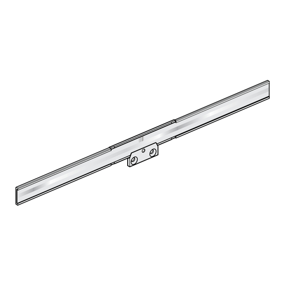
- Page 1 Mounting Instructions Montageanleitung Instructions de montage Istruzioni di montaggio Instrucciones de montaje LIDA 407 Parts Kit For mounting the scanning head, please refer to the separate Instructions. Teilesatz Für Montage des Abtastkopfes bitte separate Anleitung beachten. Jeu de pièces Pour le montage de la tête captrice, veuillez tenir compte des instructions distinctes.
-
Page 2: Table Des Matières
Contents Page Seite Inhalt Warnings Warnhinweise Sommaire Items Supplied Lieferumfang Indice Mounting Procedure Hinweise zur Montage Mounting Montage Indice 12 Mounting the Magnets for Limit Switches 12 Anbau der Magneten für Limitschalter Page Pagina Página Recommandations Avvertenze Advertencias Contenu de la fourniture Standard di formitura Suministro Procédure de montage... -
Page 3: Recommandations
Warnings Warnhinweise Recommandations Avvertenze Advertencias Note: Mounting is to be conducted by a qualified specialist under compliance with local safety regulations. The system must be disconnected from power! Achtung: Die Montage ist von einer qualifizierten Fachkraft unter Beachtung der örtlichen Sicherheitsvorschriften vorzunehmen. Die Anlage muss spannungsfrei geschaltet sein! Attention : Seul un personnel qualifié... -
Page 4: Contenu De La Fourniture
Instrucciones de montaje LIC 4007 9/2014 LIDA 407 parts kit. Teilesatz LIDA 407 . Jeu de pièces LIDA 407 . Set componenti LIDA 407 . Juego de piezas LIDA 407 . Order separately: Scale-tape carrier segments secured with PRECIMET Roller for mounting the scale tape carriers Separat bestellen: Maßbandträger-Teilstücke mit PRECIMET geklebt... -
Page 5: Avvertenze Per Il Montaggio
Mounting Procedure Hinweise zur Montage Procédure de montage Avvertenze per il montaggio Indicaciones para el montaje Choose a mounting attitude such that the maximum traverse range is within the measuring length ML of the encoder. Protect the graduation from direct contamination. Anbau so wählen, dass der maximale Verfahrweg innerhalb der Messlänge ML des Messgerätes liegt. -
Page 6: Montaggio
Mounting Montage Montage Montaggio Montaje Mounting tolerances F = Machine guideway 0.05/500 Anbautoleranzen Ra3.2 // 0.1 F = Maschinenführung Tolérances de montage F = Guidage de la machine Tolleranze di montaggio F = Guida della macchina Tolerancias de montaje F = Guía de la máquina 40±0.1 20±0.1... - Page 7 . . . 5 3 0 0 . . . 5 Attach the stop pins or the stop rail. Anschlagstifte oder Anschlagleiste anbringen. Fixer les goupilles ou la barrette d‘arrêt. Utilizzare spine o guida per battuta..5 .
- Page 8 The mounting surface must be free of paint, dust, or grease. *) Mounting surface for magnets Auf lack-, staub- und fettfreie Montagefläche achten! *) Montagefläche für Magnete ML + 30 S’assurer que la surface de montage est bien propre (exempte de peinture, poussière, traces de graisse) ! >35x8 *) *) Surface de montage pour aimants...
- Page 9 Maintain spacing, due to thermal expansion. Abstände wegen thermischer Ausdehnung einhalten. Bien respecter les distances de montage en raison de la dilatation thermique. Rispettare le distanze a causa della dilatazione termica. Mantener las distancias por causa de la dilatación térmica. Make sure that the scale-tape carriers are positioned correctly.
- Page 10 Starting from the center, evenly press the scale-tape carriers onto the mounting surface using the roller. Remove the stop pins or aligning rail. The mounting film will reach its maximum adhesive strength after approximately 70 hours at room temperature. Maßbandträger mit dem Roller von der Mitte aus gleichmäßig anpressen. Anschlagstifte oder Anschlagleiste entfernen.
- Page 11 Ensure correct position of reference mark track: Reference mark is above incremental track if cable outlet is at right. Auf die richtige Lage der Referenzmarkenspur achten. Referenzmarke oben, bei Kabelabgang rechts. Respecter la position de la piste de référence. La marque de référence doit être en haut, avec la sortie de câble à...
-
Page 12: Montaggio Dei Magneti Per Finecorsa
Mounting the Magnets for Limit Switches Anbau der Magneten für Limitschalter Montage des aimants pour commutateurs de fin de course Montaggio dei magneti per finecorsa Montaje de los imanes para el contacto final de carrera The limit switches can be used to indicate the end of the machine traversing range. - Page 13 To display the switching point, use an adapter. To do this, move the scanning head to the desired position and insert the magnet. Mit einem Adapter kann der Schaltpunkt angezeigt werden. Dazu den Abtastkopf an die gewünschte Position fahren und den Magnet einschieben. Le point de commutation peut être affiché...
- Page 14 Move the magnet until diode L1 or L2 lights up. Mark the position of the magnet (ensure that the mounting surface is clean), peel off the protective foil and apply the magnet. Magnet verschieben bis Diode von L1 bzw. L2 aufleuchtet. Stelle des Magneten markieren (auf saubere Montageflächen achten), Schutzfolie abziehen und Magnet ankleben.
- Page 16 DR. JOHANNES HEIDENHAIN GmbH Dr.-Johannes-Heidenhain-Straße 5 83301 Traunreut, Germany { +49 8669 31-0 | +49 8669 32-5061 E-mail: info@heidenhain.de Technical support | +49 8669 32-1000 Measuring systems { +49 8669 31-3104 E-mail: service.ms-support@heidenhain.de TNC support { +49 8669 31-3101 E-mail: service.nc-support@heidenhain.de...


