Table des Matières
Publicité
Liens rapides
Incremental linear encoder with large mounting tolerance
Inkrementales Längenmessgerät mit großer Anbautoleranz
Système de mesure linéaire incrémental avec une grande tolérance de montage
Sistema di misura lineare incrementale con ampia tolleranza di montaggio
Sistema lineal de medida incremental con gran tolerancia de montaje
These mounting instructions refer to:
Diese Montageanleitung ist gültig für:
Ce Guide d'installation est valable pour :
Le presenti istruzioni di montaggio si applicano per:
Estas instrucciones de montaje són válidas para:
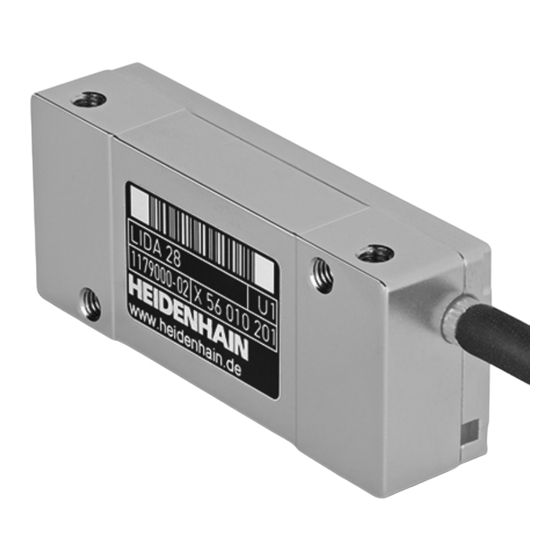
LIDA 277/287
LIDA 279/289
Mounting Instructions
Montageanleitung
Instructions de montage
Istruzioni di montaggio
Instrucciones de montaje
AK LIDA 27
AK LIDA 28
Scanning head
Abtastkopf
Tête captrice
Testina di scansione
Cabezal captador
09/2017
Publicité
Table des Matières

Sommaire des Matières pour HEIDENHAIN AK LIDA 27
- Page 1 Incremental linear encoder with large mounting tolerance Inkrementales Längenmessgerät mit großer Anbautoleranz Système de mesure linéaire incrémental avec une grande tolérance de montage AK LIDA 27 Sistema di misura lineare incrementale con ampia tolleranza di montaggio Sistema lineal de medida incremental con gran tolerancia de montaje...
-
Page 2: Table Des Matières
Contents Inhalt Contenu Indice Índice Page Seite Page 3 Warnings 3 Warnhinweise 3 Avertissements 4 Items supplied 4 Lieferumfang 4 Contenu de la livraison 5 Possibilities for mounting the scanning head 5 Montagemöglichkeiten des Abtastkopfes 5 Possibilités de montage de la tête captrice 6 Assembly 6 Montage 6 Montage... -
Page 3: Warnings
Warnings Warnhinweise Avertissements Avvertenze Advertencias Note: Mounting and commissioning is to be conducted by a qualified specialist under compliance with local safety regulations. Do not engage or disengage any connections while under power. The system must be disconnected from power! Achtung: Die Montage und Inbetriebnahme ist von einer qualifizierten Fachkraft unter Beachtung der örtlichen Sicherheitsvorschriften vorzunehmen. -
Page 4: Items Supplied
Items supplied Lieferumfang Contenu de la livraison Standard di fornitura Suministro Spacer foil Abstandsfolie Feuille d'écartement Pellicola distanziatrice Lámina espaciadora 0.75 mm... -
Page 5: Possibilità Di Montaggio Della Testina Di Scansione
Possibilities for mounting the scanning head Mounting clearance between scanning head and scale tape Montagemöglichkeiten des Abtastkopfes Montageabstand Abtastkopf zu Maßband Possibilités de montage de la tête captrice Distance de montage entre la tête captrice et le ruban de mesure Possibilità... -
Page 6: Montaggio
Assembly Montage Montage Montaggio Montaje Remove protective film. Do not touch the graduation. Schutzfolie entfernen. Teilung nicht berühren. Retirer la feuille protectrice. Ne pas toucher la gravure. Rimuovere la pellicola protettiva. Non toccare la graduazione. Retirar la lámina de protección. No rozar la graduación. If necessary: Clean the graduation of the scale tape and scanning head with a lint-free cloth and distilled spirit or isopropyl alcohol. - Page 7 Use the spacer foil to set the mounting clearance to 0.75 mm. Screw on the scanning head (M = 1.15 Nm). Mit Abstandsfolie 0.75 mm Montageabstand einstellen. Abtastkopf anschrauben (M = 1.15 Nm). Avec la feuille d'écartement, régler l'écart de montage de 0,75 mm. Visser la tête captrice (M = 1,15 Nm).
- Page 8 Permissible bending radii of connecting cables. : For rigid configuration, R : For frequent flexing Ø Zulässige Biegeradien der Anschlusskabel. : Dauerbiegung, R : Wechselbiegung ¬ 4.3 mm ‡ 10 mm ‡ 50 mm Rayons de courbure admissibles pour les câbles de raccordement. ¬...
-
Page 9: Operazioni Finali
Final steps Abschließende Arbeiten Opérations finales Operazioni finali Trabajos finales Check the resistance between the connector housing and the machine. Nominal value: 1 max. Elektrischen Widerstand zwischen Steckergehäuse und Maschine prüfen. Sollwert: 1 max. Contrôler la résistance électrique entre le boîtier du connecteur et la machine. Valeur nominale : 1 ... - Page 10 Checking the Status Display Funktionsanzeige überprüfen Vérif er l’aff chage fonctionnel Verif ca funzionalità Comprobar el indicador de función The integrated status display permits both a qualified judgment of the incremental signals as well as a check of the reference mark signal. If, after adjustment, the LED does not stay constantly green, or when the reference mark is scanned it turns briefly blue, check the installation toler- ances and repeat the adjustment.
- Page 11 As an option, a PWT 100 encoder diagnostic kit can be used for the adjustment. For further information, refer to the PWT 100 operating instructions (scope of delivery includes CD), chapter “Diagnostics of the measuring devices. ” Optional kann zur Justage ein Messgerät-Diagnoseset PWT 100 verwendet werden. Weitere Informationen siehe Betriebsanleitung PWT 100 (Lieferumfang CD), Kapitel „Diagnose der Messgeräte“...
- Page 12 DR. JOHANNES HEIDENHAIN GmbH Dr.-Johannes-Heidenhain-Straße 5 83301 Traunreut, Germany { +49 8669 31-0 | +49 8669 32-5061 E-mail: info@heidenhain.de Technical support | +49 8669 32-1000 Measuring systems { +49 8669 31-3104 E-mail: service.ms-support@heidenhain.de NC support { +49 8669 31-3101 E-mail: service.nc-support@heidenhain.de...


