Table des Matières
Publicité
Les langues disponibles
Les langues disponibles
Liens rapides
Notre personnel du service à la clientèle est disponible pour vous aider.
Pour obtenir de l'aide pour le montage de votre produit, pour signaler
des pièces endommagées ou manquantes ou pour toute autre
information, veuillez composer notre numéro sans frais : 1 866 206-0888.
Vous aurez besoin de ce manuel pour les instructions de sécurité, les procédures d'utilisation et la garantie.
Conservez-le avec votre facture originale dans un endroit sûr et au sec pour consultation future.
You will need this manual for safety instructions, operating procedures, and the warranty.
Keep it and the original sales invoice in a safe, dry place for future reference.
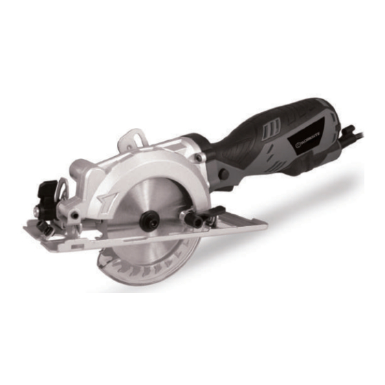
SCIE CIRC. COMP. 4 1/2'' 5,8 A
COMP. CIRC. SAW 4 1/2" 5.8 AMP
Questions? 1-866-206-0888
Conservez ce manuel
Save this manual
Modèle/Model : CSW198
Our customer service staff is available to help you.
For help with product assembly, to report damaged or missing parts, or
for any other information, please call our toll-free number:
1-866-206-0888.
ator's Manual
Manuel de l'utilisateur (p. 2)
Operator's Manual (p.15)
68125169
Publicité
Table des Matières

Sommaire des Matières pour Worksite CSW198
- Page 1 68125169 Modèle/Model : CSW198 SCIE CIRC. COMP. 4 1/2’’ 5,8 A ator’s Manual Manuel de l’utilisateur (p. 2) COMP. CIRC. SAW 4 1/2" 5.8 AMP Operator’s Manual (p.15) Questions? 1-866-206-0888 Notre personnel du service à la clientèle est disponible pour vous aider.
-
Page 2: Mesures De Sécurité Importantes
TABLE DES MATIÈRES p. 2 INSTRUCTIONS DE SÉCURITÉ IMPORTANTES p. 4 MESURES DE SÉCURITÉ POUR LA SCIE CIRCULAIRE p. 6 SPÉCIFICATIONS p. 6 VUE D’ENSEMBLE DES COMPOSANTS p. 7 MONTAGE p. 9 FONCTIONNEMENT p. 11 ENTRETIEN p. 11 GARANTIE p.12 LISTE DES PIÈCES p. -
Page 3: Instructions De Sécurité Importantes
INSTRUCTIONS DE SÉCURITÉ IMPORTANTES e. Lors de l’utilisation d’un outil électrique à l’extérieur, utiliser une rallonge pour l’extérieur marquée « W-A » ou « W ». Ces cordons sont classés pour usage extérieur et réduisent le risque de choc électrique. 4. -
Page 4: Mesures De Sécurité Pour La Scie Circulaire
INSTRUCTIONS DE SÉCURITÉ IMPORTANTES a. Tool service must be performed only by qualified repair personnel. 6. RÉPARATIONS Service or maintenance performed by unqualified personnel could result in a a. La réparation d’un outil doit être exécutée par du personnel autorisé uniquement. risk of injury. - Page 5 SAFETY PRECAUTIONS FOR CIRCULAR SAW MESURES DE SÉCURITÉ POUR LA SCIE CIRCULAIRE 5. Toujours veiller à ce que le protège-lame inférieur recouvre la lame avant de déposer la scie sur l’établi ou sur le plancher. Une lame non protégée qui tourne librement fera « marcher » la scie vers l’arrière, coupant tout sur son passage.
-
Page 6: Vue D'ensemble Des Composants
SPECIFICATIONS SPÉCIFICATIONS Scie circulaire * Tension nominale : 120 V, 60 Hz * Courant d’entrée : 5,8 A * Vitesse à vide : 3500 tr/min * Lame : 4 1/2 po * Diamètre de l’arbre : 3/8 po * Capacité de coupe maximale :1 3/4 po * Angles de coupe : 0°-45°... -
Page 7: Montage
MONTAGE Vérifier que l’outil, les pièces et les accessoires n’ont pas été endommagés, ce qui peut s’être produit pendant le transport. Prendre le temps de lire attentivement ce manuel et d’en comprendre tout le contenu avant le montage et l’utilisation. MISE EN GARDE Toujours s’assurer que l’outil est éteint et débranché... -
Page 8: Allumer Et Éteindre
Allumer et éteindre Note ’ ’ Avant d utiliser l interrupteur marche/arrêt, vérifier la lame de scie pour voir si elle est correctement installée, qu’elle tourne en douceur, et que la vis de serrage de la lame est correctement serrée. ’... -
Page 9: Fonctionnement
Raccordement du tuyau pour la poussière - Insérer l’adaptateur du tuyau pour la poussière (R) dans la sortie pour la poussière (Q). - Raccorder l’autre extrémité du tuyau pour la poussière à un aspirateur ou à un extracteur de poussière approprié... - Page 10 Fig. 8 NOTE Pour obtenir de meilleurs résultats de coupe, toujours s’assurer que la lame de la scie ne dépasse pas de plus de 1/8 po la surface inférieure de la pièce. NOTE Il y a deux encoches sur le bord avant de la semelle qui aident pour l’alignement. Lorque vous faites une coupe en biseauu de 45 ⁰...
- Page 11 GARANTIE Merci d’avoir acheté cet outil WORKSITE. Ces outils ont été conçus pour répondre à des normes de haute qualité très strictes et sont garantis pour usage domestique contre tout défaut de fabrication, et ce, pour une durée de 24 mois à compter de la date d’achat.
-
Page 12: Liste Des Pièces
LISTE DES PIÈCES Veuillez vous référer au diagramme schématique de la page 13. Num. Description Qté Num. Description Qté Vis pan head Phillips M4×14 (avec rondelle) Logement gauche Vis pan head Phillips Vis pour ressort de traction Ressort pour verrouillage d’arbre Rondelle pour ressort Couvercle de boîte d’engrenages Capuchon de verrouillage d’arbre... - Page 13 SCHEMATIC DRAWING /SCHEMATIC DIAGRAM DIAGRAMME SCHÉMA AVERTISSEMENT : Les réparations doivent être faites par un centre de services autorisé. Ne pas ouvrir ou démonter cet outil électrique. WARNING: Repairs should be made by an authorized repair center. Do not open or disassemble this power tool.
-
Page 14: Parts List
PARTS LIST the schematic diagram Description Description Phillips pan head screw M4X14 Left housing (with washer) Phillips pan head screw Screw for tension spring Spring for spindle lock Spring washer Gear box cover Spindle lock cap Circlip Tension spring Square-head bolts Trigger Deep groove ball bearing 698 Spindle lock spring... - Page 15 TABLE OF CONTENTS p.13 SCHEMATIC DIAGRAM p.14 PARTS LIST p.15 p.17 SAFETY PRECAUTIONS FOR CIRCULAR SAWS SPECIFICATIONS p.17 p.18 OVERVIEW OF COMPONENTS p.18 ASSEMBLY p.21 OPERATING PROCEDURES MAINTENANCE p.23 WARRANTY p.23 IMPORTANT SAFETY INSTRUCTIONS WARNING: When using electric tools, machines or equipment, basic safety shock and personal injury.
-
Page 16: Important Safety Instructions
IMPORTANT SAFETY INSTRUCTIONS c. Avoid accidental starting. Be sure switch is off before plugging in. Carrying tools with your finger on the switch or plugging in tools that have the switch on invites accidents. d. Remove adjusting keys or switches before turning the tool on. A wrench or a key that is left attached to a rotating part of the tool may result in personal injury. - Page 17 IMPORTANT SAFETY INSTRUCTIONS 7. Hold tool by its insulated gripping surfaces when performing an operation where the blade may contact hidden wiring or its own cord. Contact with a “live” wire will make exposed metal parts of the tool “live” and shock the operator.
-
Page 18: Circular Saw
SAFETY PRECAUTIONS FOR CIRCULAR SAW 10. Causes and operator prevention of kickback: Kickback is a sudden reaction to a pinched, bound or misaligned saw blade, causing an uncontrolled saw to lift up and out of the workpiece toward the operator. When the blade is pinched or bound tightly by the kerf closing down, the blade stalls and the motor reaction drives the unit rapidly back toward the operator. -
Page 19: Changing The Blade
OVERVIEW OF COMPONENTS Fig. 1 A - Saw blade Lower guard B - Switch Base plate C - Lock button Storage for hexagon key D - Upper guard Spindle lock E - Bevel locking lever Depth locking lever F - Parallel guide lock screw Depth scale G - Parallel guide Dust outlet... -
Page 20: Parallel Cut Adjustment
centred - Make sure the the blade rotates in the same direction as the tool. Refer to the direction arrows on the tool and on the saw blade. - Reinstall the outer flange and washer, and tighten the blade clamp sc rew. - Turn the blade by hand to make sure the saw blade can run freely. -
Page 21: Depth Adjustment
Depth Adjustment - Before making any adjustment, ensure the power plug is removed from the socket. - Loosen the depth adjustment screw using the depth locking lever (O). piece and lift the body of the saw until the blade is at the correct depth. - Page 22 OPERATION General Cut - Mark a cutting line on the workpiece (U). touching the workpiece. - Switch on the tool and allow it to reach its full speed. - Align the saw blade with the cutting line on the workpiece. Gently push the saw forward. - Never force the saw but maintain light and continuous pressure until completing the cut.
-
Page 23: Cutting Large Sheets
Pocket Cut - Disconnect the plug from the power supply before making any adjustments. - Set the depth adjustment based on the thickness of the required cut. - Raise the lower guard using the lower guide lever. - With the blade just above the material to be cut, start the saw and allow the blade to attain full speed. - Page 24 WARRANTY Thank you for investing in a WORKSITE power tool. These products have been made to demanding, high-quality standards and are guaranteed for domestic use against manufacturing faults for a period of 24 months from the date of purchase.