Publicité
Les langues disponibles
Les langues disponibles
Liens rapides
For application in refrigeration systems and heat
pumps
Technical data:
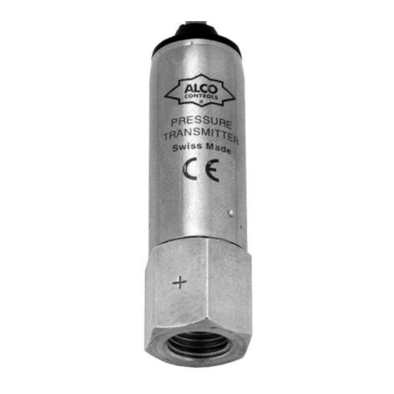
PT3 senses pressure and generates a pressure
proportional output signal. The sensor works
internally as
an
absolute measuring
However, it is calibrated to produce a relative output
signal assuming an ambient pressure of 1.0 bar.
• Pressure range (bar):
PT3-07: -0.8 (-0.6)...7
PT3-18:
PT3-30:
Value in
brackets indicates
measurable value for PT3-xxU.
• Test pressure (bar):
PT3-07: 25
PT3-18: 36
PT3-30: 36
• Supply voltage:
2-wire: 8..28V DC,
3-wire: 10..28V DC
reverse polarity protection for supply lines
• Permissible noise & ripple:
• Output signal:
PT3-..A: 4...20mA
PT3-..V: 1... 6V
PT3-..U: 0...10V
• Load resistance (PT3-...A):
R < (Supply voltage - 8 V) / 0.02 A
• Total error (including hysteresis, repeatability,
linearity):
PT3-07:
PT3-18 / -30:
betw. 18°C...22°C:
±1.5%
betw. 0°C...50°C:
±2.5%
betw. -20°C...70°C: ±4.5%
±4.5% of full scale
• Influence of supply voltage:
factory calibrated at 24V DC
• Medium compatibility:
PT3__65027__R06
Replacement for PT3__65027__R05
Installation Instructions
Pressure Transmitter
PT3
• Medium temperature:
• Storage and transport temp.:
• Ambient temp. (housing):
• Protection class (DIN 43650): IP65
• Electromagnetic compatibility: shielded
connected to sensor housing
device.
• CE-mark
91/263/EC, 92/31/EC, 93/68/EC
• EMC standards applied: IEC 801-2, -3, -4, -6
!
0 (0.5)...18
Safety instructions:
0 (0.8)...30
• Read
actual lowest
Failure to comply can result in device failure,
system damage or personal injury. Before
opening any system, pressure must be brought
to and remain at atmospheric pressure.
• Ensure supply voltage matches specified range
of PT3. Disconnect supply voltage from
system/PT3 before installation/service. Comply
with local electrical regulations when wiring
PT3.
• Electronic devices are subject to electro
< 1 V
p-p
magnetic
components in the system are sufficiently
protected.
• Improper installation of cabel between pressure
transducer and electronic system may affect the
output signal of the pressure transducer. Cable
lengths exceeding 2 m may have a negative
±1.0% of full scale
impact on electromagnetic compatibility.
• PT3 are factory set. The setting cannot be
±2.5% of full scale
changed.
• Do not exceed proof pressure.
< 0,04 %/V,
HFC, HCFC, CFC
Emerson Climate Technologies GmbH
GB
Holzhauser Str. 180 - D-13509 Berlin
-40...135°C
-40.....85 °C
-30.....70°C
under
EC
Directive
89/336/EC,
installation
instructions
thoroughly.
interference.
Ensure
that
PCN 862480
Germany
www.emersonclimate.eu
• Keep temperatures within nominal limits.
Sensor body temperature must not exceed 70°C
in high medium temperature applications.
• Allow 5 minutes stabilisation time after
cable
connecting sensor supply voltage before taking
any accurate measurements.
• PT3 assumes an ambient pressure of 1.0 bar.
When using PT3 in heights significantly above
sea level the deviation in output signal must be
taken into account. I.e. at a height of 1.000 m
the signal reads ca. 0.1 bar lower than the
actual pressure is.
Mounting:
• Flare connection: do not exceed max. torque of
15Nm.
• Mounting position: as desired
Wiring:
• Two wire connection: see Fig. 2
• Three wire connection: see Fig. 3
• The cable shield is connected to the sensor housing
side only, do not connect the shield at the signal
processing side!
all
Replacement of transmitters:
• PT3
can
directly
transmitters PT1 and PT2 (same pressure and
signal ranges provided!)
• APT as well as other three wire pressure
transmitters with 4...20mA output signal, see Fig.
4 and Fig. 5 for comparison of old and new
installation.
Dimensions: see Fig. 1
10.07.2013
replace
former
ALCO
Publicité

Sommaire des Matières pour Emerson ALCO controls PT3
- Page 1 Installation Instructions Emerson Climate Technologies GmbH Pressure Transmitter Holzhauser Str. 180 - D-13509 Berlin Germany www.emersonclimate.eu • Medium temperature: • Keep temperatures within nominal limits. For application in refrigeration systems and heat -40...135°C • Storage and transport temp.: pumps -40..85 °C Sensor body temperature must not exceed 70°C...
- Page 2 Einbauanleitung Emerson Climate Technologies GmbH Drucktransmitter Holzhauser Str. 180 - D-13509 Berlin Germany www.emersonclimate.eu • Medientemperatur: • Überschreiten Sie niemals den maximalen Für Kälteanlagen und Wärmepumpen -40...135°C • Lager- und Transporttemp.: -40...85°C Prüfdruck! Technische Daten: • Umgebungstemp. (Gehäuse): • Halten -30...70°C...
-
Page 3: Transmetteur De Pression
Instructions d'Installation Emerson Climate Technologies GmbH Transmetteur de pression Holzhauser Str. 180 - D-13509 Berlin Germany www.emersonclimate.eu • Transport et stockage: - 40°.….85°C • Le Pour application dans les systèmes de réfrigération réglé pour pression • Température ambiante (corps): - 30°.….70°C et pompe à... - Page 4 Instrucciones de Instalacion Emerson Climate Technologies GmbH Transductor de presión Holzhauser Str. 180 - D-13509 Berlin Germany www.emersonclimate.eu • Temperatura del fluido: -40°...135°C • Mantener las temperaturas dentro de los límites Para aplicación en circuitos de refrigeración y • Temperatura de almacenaje y transporte: bomba de calor nominales.
-
Page 5: Trasduttore Di Pressione
Istruzioni per l'Installazione Emerson Climate Technologies GmbH Trasduttore di pressione Holzhauser Str. 180 - D-13509 Berlin Germany www.emersonclimate.eu • Compatibilità Elettromagnetica: cavo schermato Utilizzato per applicazioni con sistemi refrigeranti e La temperatura del corpo del sensore non deve pompe di calore connesso all' alloggiamento del sensore. - Page 6 Installatievoorschrift Emerson Climate Technologies GmbH Druktransmitter Holzhauser Str. 180 - D-13509 Berlin Germany www.emersonclimate.eu • Mediumtemperatuur: Voor koelsystemen en warmtepompen temperaturen alle tijde binnen -40...135ºC • Opslag- en transport temp: aangegeven grenzen. De temperatuur van de -40...80ºC Beschrijving: • Omgevingstemperatuur(behuizing): -30...70ºC behuizing mag 70ºC niet overschrijden.
- Page 7 / marrone / marron ALCO APT..blane / bianco / blanco vert / verde / verde Fig. 3: Fig. 4: Fig. 5: Emerson Climate Technologies GmbH Holzhauser Str. 180 – D-13059 Berlin Germany www.emersonclimate.eu PT3__65027__R06 Replacement for PT3__65027__R05 PCN 862480 10.07.2013...


