Table des Matières
Publicité
Les langues disponibles
Les langues disponibles
Liens rapides
MPM_UM_9752080610_NL_D_GB_F_V3_2
Multi Power Master
(MPM)
Voedingsapparaat
Power Unit
NL
Gebruikershandleiding
D
Bedienungsanleitung
GB
User's Manual
F
Notice d'utilisation
Simco-Ion Netherlands
Postbus 71
NL-7240 AB Lochem
Telefoon +31-(0)573-288333
Telefax
+31-(0)573-257319
E-mail
general@simco-ion.nl
Internet
http://www.simco-ion.nl
Traderegister Apeldoorn No. 08046136
Netzteil
Appareil d'alimentation
1
20
39
58
Publicité
Chapitres
Table des Matières

Manuels Connexes pour ITW Simco-Ion Multi Power Master

Sommaire des Matières pour ITW Simco-Ion Multi Power Master
- Page 1 Simco-Ion Netherlands Postbus 71 NL-7240 AB Lochem Telefoon +31-(0)573-288333 Telefax +31-(0)573-257319 E-mail general@simco-ion.nl Internet http://www.simco-ion.nl Traderegister Apeldoorn No. 08046136 Multi Power Master (MPM) Voedingsapparaat Netzteil Power Unit Appareil d'alimentation Gebruikershandleiding Bedienungsanleitung User's Manual Notice d'utilisation MPM_UM_9752080610_NL_D_GB_F_V3_2...
-
Page 2: Table Des Matières
INHOUDSOPGAVE Woord vooraf ..........................2 Verklaring gebruikte symbolen ..................... 2 1 Inleiding ..........................3 2 Beschrijving en werking ......................4 3 Veiligheid ..........................4 4 Technische specificaties ......................5 4.1 Specificaties ........................5 4.2 Maximale belasting ......................6 5 Installatie ..........................7 5.1 Controle .......................... -
Page 3: Woord Vooraf
Woord vooraf Deze handleiding is bedoeld voor installatie en gebruik van het voedingsapparaat type MPM. Deze handleiding moet altijd toegankelijk zijn voor het bedieningspersoneel. Lees deze handleiding geheel door voordat u dit product installeert en in gebruik neemt. Instructies in deze handleiding moeten worden opgevolgd om een goede werking van het product te waarborgen en om aanspraak te kunnen maken op garantie. -
Page 4: Inleiding
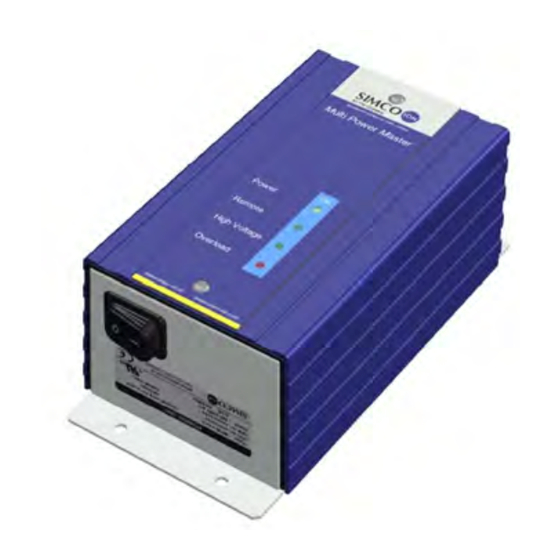
1 Inleiding De Multi Power Master (MPM) dient als voedingsbron voor Simco-Ion ionisatieapparatuur. Deze ionisatieapperatuur wordt gebruikt voor het ontladen van elektrostatisch opgeladen materialen. De MPM is leverbaar in 4 uitgangsspanningsvarianten met een sinusvormige uitgangsspanning van 3,3 kV, 4,0 kV, 5,0 kV of 7,0 kV. Indicatieleds op het deksel geven de status van de MPM weer. -
Page 5: Beschrijving En Werking
2 Beschrijving en werking De MPM levert de hoogspanning voor ionisatieapparatuur van Simco-Ion. Er zijn vier hoogspanningsuitgangen waarop ionisatieapparatuur kan worden aangesloten. De hoogspanning is gestabiliseerd en beschermd tegen overbelasting. De indicatieleds op het deksel geven de status van de MPM weer: - [Power] : MPM aan. -
Page 6: Technische Specificaties
4 Technische specificaties 4.1 Specificaties Ingangsspanning nominaal 100 – 240 V AC Ingangsspanning limietwaarden 88 – 264 V AC Ingangsstroom 0,7 - 0,3 A Frequentie nominaal 50 – 60 Hz Frequentie limietwaarden 47 – 63 Hz Uitgangsspanning MPM-23x: 3,3 kV AC ±5% MPM-24x: 4,0 kV AC ±5% MPM-25x: 5,0 kV AC ±5% MPM-27x: 6,4 kV AC ±5%... -
Page 7: Maximale Belasting
4.2 Maximale belasting De belasting van de MPM bestaat uit de aangesloten ionisatieapparatuur en de daarbij gebruikte afgeschermde aansluitkabel. De capacitieve belasting van de apparatuur en van de kabels moet bij elkaar worden opgeteld om de totale belasting van de MPM te berekenen. Let op: - De maximale uitgangsstroom van de MPM is 3 mA. -
Page 8: Installatie
Bijvoorbeeld, een combinatie van twee ionisatiestaven aan één MPM: ♦ één MEB ionisatiestaaf met een effectieve lengte van 2 meter en aangesloten met 3 meter afgeschermde hoogspanningskabel: 2 x 75 pF + 3 x 125 pF = 525 pF ♦ één P-Sh-N ionisatiestaaf met een effectieve lengte van 3 meter en aangesloten met 4 meter afgeschermde hoogspanningskabel: 3 x 100 pF + 4 x 125 pF = 800 pF ♦... -
Page 9: Mpm Monteren
Bodemplaat Afbeelding 2: montagegaten MPM Aansluitkabels Hoogspanningskabels ionisatie-apparatuur Netsnoer Aan/uit- schakelaar Externe aarddraad (kabeloog ø6 mm) Aansluitblok voor de Bandkabelconnector Dipswitches hoogspanningskabels I/O-connector (MPM-xxR) Afbeelding 3: installeren MPM (weergegeven zonder deksel) 5.2.2 MPM monteren - Bevestig de MPM aan een stabiel wand of machinedeel, met behulp van de ø6 mm bevestigingsgaten in de bodemplaat. -
Page 10: Ionisatieapparatuur Aansluiten
5.3 Ionisatieapparatuur aansluiten - Draai de twee schroeven aan de bovenkant van het deksel los. - Verwijder het deksel voorzichtig van de MPM. Let op dat de bandkabel tussen het deksel en de printplaat van de MPM niet beschadigd. - Verwijder de afdichtingen (blindstoppen) uit de positie waar de kabel van de ionisatieapparatuur doorgevoerd moeten worden. - Page 11 Let op: Onderliggende isolatielagen niet beschadigen! Hoogspanningskabels tijdens het strippen niet scherper buigen dan radius 45 mm. Scherper ombuigen verkort de levensduur van de kabel! Afbeelding 5: kabelmantel strippen Algemene instructies voor het correct strippen van kabelmantels: - Gebruik bij voorkeur een speciaal kabelmes of anders een scherp mes voor het strippen van kabels.
- Page 12 Rood Coaxkabel Adereindhuls Afbeelding 6: afwerking coaxkabel Blauwe PVC-laag verwijderen Afgeschermde HS-kabel Afbeelding 7: afwerking blauwe HS-kabel MPM_UM_9752080610_NL_D_GB_F_V3_2...
-
Page 13: Hoogspanningskabel Met Losse Gevlochten Afscherming
5.3.2 Hoogspanningskabel met losse gevlochten afscherming Let op: Bij hoogspanningskabel met gevlochten afscherming moet alleen de witte Teflonslang in de wartel steken. Draai de wartelmoer vast. De aardaansluiting van gevlochten afscherming moet gemonteerd worden aan het externe aardpunt van het voedingsapparaat. Zie ook afbeelding 8a. -
Page 14: Mpm Opties
6 MPM opties Waarschuwing: - Elektrische installatie moet gebeuren door een elektrotechnisch vakbekwaam persoon. - Bij werkzaamheden aan de apparatuur moet de apparatuur spanningsloos zijn. 6.1 Afstandbedieningskabel aansluiten (MPM-xxR) De optie afstandsbediening kan alleen worden gebruikt als de MPM is voorzien van een I/O-connector. -
Page 15: Hoogspanning Aan"-Signalering Op Afstand
Functie Aan/Uit op afstand Uit Functie Aan/Uit op afstand Aan Dipswitch 1 [OFF] Dipswitch 1 [ON] Afbeelding 11: functie Aan/Uit op afstand in- of uitschakelen 6.3 "Hoogspanning AAN"-signalering op afstand Met de "Hoogspanning AAN"-signalering kan op afstand worden gecontroleerd of er hoogspanning op de uitgang van de MPM aanwezig is. -
Page 16: Biphase Regeling
Functie Ionenbalans Aan Functie Ionenbalans Uit Dipswitch 2 [OFF] Dipswitch 2 [ON] Afbeelding 12: functie Ionenbalans in- of uitschakelen 6.7 Biphase regeling Met de Biphaseregeling is het mogelijk om de uitgangsspanning van 2 MPM voedingapparaten in tegenfase te schakelen. Door gebruik te maken van 2 MPM voedingsapparaten in Biphase-opstelling ontstaan er aan de aangesloten ionisatie-apparatuur gelijktijdig positieve en negatieve ionen, waardoor materiaal ook bij hoge materiaalsnelheden wordt geneutraliseerd. -
Page 17: Ingebruikneming En Bediening
Standaard staat een MPM ingesteld als "Master". Om een MPM in te stellen als “Slave” moet dipswitch 3 in de stand [ON] gezet worden. Wanneer de MPM niet in Biphase-opstelling wordt gebruikt moet dipswitch 3 in de stand [OFF] staan. Om dipswitch 3 om te zetten moet het deksel van de MPM tijdelijk verwijderd worden (Afbeelding 3). -
Page 18: Power] Led Knippert Langzaam (Biphase)
8.2 [Power] led knippert langzaam (Biphase) Wanneer gebruik wordt gemaakt van de Biphase-optie (zie ook hoofdstuk 6.7) en de MPM in de “Slave”-stand staat knippert de led [Power] langzaam (1x per 2 seconden). Dit geeft aan dat de “Slave”-MPM een synchronisatiesignaal ontvangt van de "Master"-MPM. 8.3 [Power] led knippert snel (Foutindicatie) De led [Power] knippert snel (2x per seconde) wanneer de externe 24VDC-uitgang van de MPM te zwaar wordt belast. -
Page 19: Storingen
10 Storingen Waarschuwing: - Bij werkzaamheden aan de apparatuur moet de apparatuur spanningsloos zijn. - Reparatie moet gebeuren door een elektrotechnisch vakbekwaam persoon. 10.1 Storingenoverzicht Tabel 3: storingen Probleem Oorzaak Oplossing Alle leds zijn gedoofd Geen netspanning Netspanning inschakelen MPM is uitgeschakeld MPM inschakelen Led [Power] knippert snel Externe 24V DC (I/O-connector) -
Page 20: Reparaties
11 Reparaties Waarschuwing: - Bij werkzaamheden aan de apparatuur moet de apparatuur spanningsloos zijn. - Reparatie moet gebeuren door een elektrotechnisch vakbekwaam persoon. Simco-Ion Netherlands raadt u aan voor reparaties de MPM retour te zenden. Vraag hiervoor per e-mail een RMA-formulier aan via service@simco-ion.nl. Verpak de MPM deugdelijk en vermeld duidelijk de reden van retour. - Page 21 INHALT Vorwort ............................21 Erklärung der verwendeten Symbole ..................21 1 Einführung ........................... 22 2 Beschreibung und Funktionsweise ..................23 3 Sicherheit ..........................23 4 Technische Angaben ......................24 4.1 Spezifikationen ......................24 4.2 Maximale Belastung ...................... 25 5 Installation ........................... 26 5.1 Kontrolle ........................
-
Page 22: Vorwort
Vorwort Diese Bedienungsanleitung beschreibt die Installation und Verwendung des Netzteils vom Typ MPM. Diese Anleitung muss dem Bedienpersonal jederzeit zur Verfügung stehen. Lesen Sie sich diese Anleitung vor der Installation und Inbetriebnahme dieses Produktes vollständig durch. Befolgen Sie die Anweisungen in dieser Anleitung, um die richtige Funktionsweise des Produktes sicherzustellen und ggf. -
Page 23: Einführung
1 Einführung Der Multi Power Master (MPM) dient als Spannungsquelle für Simco-Ion Ionensprühgeräte. Diese Ionensprühgeräte werden zum Entladen elektrostatisch aufgeladener Materialien verwendet. Der MPM ist in vier Ausgangsspannungsvarianten mit einer sinusförmigen Ausgangsspannung von 3,3 kV, 4,0 kV, 5,0 kV oder 7,0 kV lieferbar. Anzeige-LEDs auf dem Deckel zeigen den Status des MPM an. -
Page 24: Beschreibung Und Funktionsweise
2 Beschreibung und Funktionsweise Der MPM liefert die Hochspannung für Simco-Ion Ionensprühgeräte. Er bietet vier Hochspannungsausgänge für den Anschluss von Ionensprühgeräten. Die Hochspannung ist stabilisiert und gegen Überlastung geschützt. Die Anzeige-LEDs auf dem Deckel zeigen den Status des MPM an: - [Power] : MPM ein - [Remote]... -
Page 25: Technische Angaben
4 Technische Angaben 4.1 Spezifikationen Eingangsnennspannung 100-240 V AC Eingangsspannung-Grenzwerte 88-264 V AC Eingangsstrom 0,7-0,3 A Frequenz nominal 50-60 Hz Frequenz-Grenzwert 47–63 Hz Ausgangsspannung MPM-23x: 3,3 kV AC ±5 % MPM-24x: 4,0 kV AC ±5 % MPM-25x: 5,0 kV AC ±5 % MPM-27x: 6,4 kV AC ±5 % Ausgangsstrom Max. -
Page 26: Maximale Belastung
4.2 Maximale Belastung Die Belastung des MPM berechnet sich aus den angeschlossenen Ionensprühgeräten und dem dafür verwendeten abgeschirmten Anschlusskabel. Die kapazitive Belastung des Geräts und der Kabel muss addiert werden, um die Gesamtbelastung des MPM zu berechnen. Achtung: - Der maximale Ausgangsstrom des MPM beträgt 3 mA. - Die maximale kapazitive Belastung des MPM beträgt 1500 pF. -
Page 27: Installation
Beispiel: eine Kombination aus zwei Ionensprühstäben an einem MPM: ♦ Ein MEB-Ionensprühstab mit einer effektiven Länge von 2 Metern, der mit 3 Meter abgeschirmtem Hochspannungskabel angeschlossen ist:2 x 75 pF + 3 x 125 pF = 525 pF ♦ Ein P-Sh-N-Ionensprühstab mit einer effektiven Länge von 3 Metern, der mit 4 Meter abgeschirmtem Hochspannungskabel angeschlossen ist:3 x 100 pF + 4 x 125 pF = 800 pF ♦... -
Page 28: Mpm Montieren
Achtung: - Die Erdung erfolgt über das Netzkabel und über den externen Erdleiter am Erdpunkt des MPM. Schließen Sie den externen Erdleiter an ein geerdetes Maschinenteil an. Bodenplatte Abbildung 2: MPM-Montageöffnungen Anschlusskabel Hochspannungskabel Ionensprühgerät Netzkabel Ein/Aus- Schalter Externes Erdungskabel (Kabelöse ø Anschlussblock für die DIP-Schalter Bandkabel-... -
Page 29: Ionensprühgerät Anschließen
5.3 Ionensprühgerät anschließen - Lösen Sie die beiden Schrauben auf der Oberseite des Deckels. - Entfernen Sie den Deckel vorsichtig vom MPM. Achten Sie darauf, dass das Bandkabel zwischen dem Deckel und der Leiterplatte des MPM nicht beschädigt wird. - Entfernen Sie die Abdichtungen (Blindstopfen) aus der Öffnung, durch die das Kabel des Ionensprühgeräts geführt werden muss. -
Page 30: Hochspannungskabel Kürzen
5.3.1 Hochspannungskabel kürzen Warnung: Elektrische Anschlussarbeiten sind von elektrotechnisch fachkundigen Personen durchzuführen. Bei der Durchführung von Arbeiten am Gerät muss das Gerät spannungslos sein. Die Hochspannungskabel der Ionensprühgeräte dürfen gekürzt werden. Die Metallabschirmung darf vom Kunden dagegen nicht verkürzt werden. Das abgeschirmte Koaxialkabel muss wie in Abbildung 6 dargestellt abisoliert werden. - Page 31 Koaxialkabel Weiß Aderendhülse Abbildung 6: Abisolieren des Koaxialkabels Blauen PVC-Mantel entfernen Abgeschirmtes HS-Kabel Abbildung 7: Fertigstellung des blauen HS-Kabels MPM_UM_9752080610_NL_D_GB_F_V3_2...
-
Page 32: Hochspannungskabel Mit Lose Geflochtener Abschirmung
5.3.2 Hochspannungskabel mit lose geflochtener Abschirmung Achtung: Bei Hochspannungskabeln mit Abschirmgeflecht nur den weißen Teflonschlauch in der Überwurfmutter stecken. Überwurfmutter festziehen. Der Erdungsanschluss des Abschirmgeflechtes muss an den externen Erdungspunkt des Stromversorgungsgeräts angeschlossen werden. Siehe auch Abbildung 8a. 5.3.3 Abgeschirmtes Hochspannungskabel Air gun ES-2J Bei dem abgeschirmten Hochspannungskabel der Air gun ES-2J den Erdungsanschluss durch die Überwurfmutter in das Stromversorgungsgerät stecken. -
Page 33: Mpm-Optionen
- Stellen Sie die beiden Erdverbindungen über das Netzkabel und über den externen Erdleiter am Erdpunkt des MPM her. Schließen Sie den externen Erdleiter an ein geerdetes Maschinenteil an. 6 MPM-Optionen Warnung: - Elektrische Anschlussarbeiten sind von elektrotechnisch fachkundigen Personen durchzuführen. -
Page 34: Hochspannung Ein"-Signalisierung Fernbedienung
Zum Umstellen von DIP-Schalter 1 muss vorübergehend der Deckel vom MPM abgenommen werden (Abbildung 3). Die LED [Remote] leuchtet und zeigt damit an, dass diese Funktion eingeschaltet ist. Um Hochspannung am Ausgang zu erhalten, müssen 10–30 V DC am Eingang „Hochspannung Ein/Aus“... -
Page 35: Ionenausgleichsregelung
6.6 Ionenausgleichsregelung Mithilfe der Ionenausgleichsregelung kann der positive und negative Ionenausgleich des angeschlossenen Ionensprühgeräts gesteuert werden. Dadurch kann die Restladung des zu entladenden Materials deutlich verringert werden. Das funktioniert nicht für kapazitiv gekoppelte (shockless) Stäbe, wie z. B. (E)P-Sh-N- und MEB-Stäbe. Um die Ionenausgleichsregelung einzuschalten, muss der DIP-Schalter 2 in die Stellung [ON] gesetzt werden. - Page 36 Abbildung 13: MPM Master und MPM Slave (Beispiel) Die LED [Power] des „Slave“-MPM blinkt langsam (1x pro 2 Sekunden), und zeigt damit an, dass der „Slave“-MPM ein Synchronisiersignal vom „Master“-MPM empfängt. Fällt das Synchronisiersignal vom „Master“-MPM aus, hört die LED [Power] des „Slave“-MPM auf zu blinken und leuchtet kontinuierlich.
-
Page 37: Inbetriebnahme Und Bedienung
7 Inbetriebnahme und Bedienung - Schalten Sie die Netzspannung für den MPM ein, oder stecken Sie den Stecker in die Wandsteckdose. - Schalten Sie den MPM mithilfe des Ein-/Ausschalters ein. Nur für den MPM mit der Fernbedienungsoption (MPM-xxR): Ist die Option „Hochspannung fernbedient ein/aus“... -
Page 38: Wartung
9 Wartung Warnung: - Bei der Durchführung von Arbeiten am Gerät muss das Gerät spannungslos sein. Der MPM enthält keine Bauteile die einer regelmäßigen Wartung bedürfen. - Sorgen Sie dafür, dass der MPM trocken und staub-, schmutz- und chemikalienfrei bleibt. - Kontrollieren Sie regelmäßig die Erdung des MPM. -
Page 39: Kurzschluss In Den Angeschlossenen Geräten Lokalisieren Und Beseitigen
10.2 Kurzschluss in den angeschlossenen Geräten lokalisieren und beseitigen Warnung: - Bei der Durchführung von Arbeiten am Gerät muss das Gerät spannungslos sein. - Gerät und Kabel mit Metallabschirmung müssen korrekt geerdet sein. Dazu müssen die Überwurfmuttern der abgeschirmten Kabel korrekt montiert sein. Erdung ist für eine einwandfreie Funktionsweise des Geräts erforderlich und verhindert einen unangenehmen Stromschlag bei Berührung. - Page 40 CONTENTS Preface ............................40 Explanation of symbols ......................40 1 Introduction .......................... 41 2 Description and operation ....................42 3 Safety ..........................42 4 Technical specifications ....................... 43 4.1 Specifications ........................ 43 4.2 Maximum load ....................... 44 5 Installation ........................... 45 5.1 Checks ..........................
-
Page 41: Preface
Preface This manual describes the installation and usage of type MPM power units. This manual must be available at all times to staff operating the equipment. Read through the entire manual before installing and commissioning the product. Follow the instructions set out in this manual to ensure proper operation of the product and to retain your entitlement under the guarantee. -
Page 42: Introduction
1 Introduction The Multi Power Master (MPM) serves as the power source for Simco-Ion ionisation equipment. This ionisation equipment is used to discharge electrostatically charged materials. The MPM is available in 4 output voltage models with a sinusoidal output voltage of 3.3 kV, 4.0 kV, 5.0 kV or 7.0 kV. -
Page 43: Description And Operation
2 Description and operation The MPM supplies the high voltage required by Simco-Ion ionisation equipment. There are four high voltage outputs to which ionisation equipment can be connected. The high voltage is stabilised and is protected against overload. LED indicators on the cover show the status of the MPM: - [Power] : MPM on. -
Page 44: Technical Specifications
4 Technical specifications 4.1 Specifications Rated input voltage 100 - 240 V AC Input voltage limit values 88 - 264 V AC Input current: 0.7 - 0.3 A Rated frequency 50/60 Hz Frequency limit values 47–63 Hz Output voltage MPM-23x: 3.3 kV AC ±5% MPM-24x: 4.0 kV AC ±5% MPM-25x: 5.0 kV AC ±5% MPM-27x: 6.4 kV AC ±5%... -
Page 45: Maximum Load
4.2 Maximum load The load on the MPM is determined by the ionisation equipment connected and the shielded connecting cable used. The capacitive load of the equipment and cables must be added together in order to calculate the total load of the MPM. Note: - The maximum output current of the MPM is 3 mA. -
Page 46: Installation
5 Installation Warning: - The electrical installation must be carried out by a skilled electrical engineer with the relevant training and qualifications. - Disconnect the power supply before carrying out work on the unit. 5.1 Checks - Check that the equipment is undamaged and that you have received the correct version. - Check that the details on the packing slip correspond to the details of the product received. -
Page 47: Fitting The Mpm
Connection cables High voltage cables for ionisation equipment Power cable On/off switch External earth wire (cable lug Terminal block for the Dipswitches Flat cable connector ø6 mm) high voltage cables I/O connector (MPM-xxR) Figure 3: Installing the MPM (shown without the cover) 5.2.2 Fitting the MPM - Attach the MPM to a stable wall or machine part using the 6-mm diameter fixing holes in the base plate. -
Page 48: Shortening High-Voltage Cables
Only for the MPM with remote control option (MPM-xxR): see chapter 6 if the remote high voltage on/off option is required The Ion balance or the Biphase option must be switched on. - Place the cover on the box. - Secure the cover with the two screws. Power unit Gland housing Coax cable... - Page 49 Figure 5: Stripping the cable sheath General instructions for stripping the cable sheath correctly: You should ideally use a specialised cable knife or a sharp knife to strip the cable. Avoid bending cables sharply while you are working on them. A Cut around the sheath at the desired length, without touching or damaging the shielding or the layer underneath.
-
Page 50: High-Voltage Cables With Loose Braided Shielding
Coax cable White Ferrule Figure 6: Coax cable finishing Remove the blue PVC layer Shielded high voltage cable Figure 7: Blue high-voltage cable finishing 5.3.2 High-voltage cables with loose braided shielding Note: In the case of high-voltage cables with braided shielding, only the white Teflon hose must be inserted into the gland. -
Page 51: Shielded High Voltage Cable Air Gun Es-2J
5.3.3 Shielded high voltage cable Air gun ES-2J With the shielded high voltage cable of the Air gun ES-2J, the earth connection must be connected to the power unit through the union nut. The earth connection must be connected to the power unit's internal earthing point. -
Page 52: Mpm Options
6 MPM options Warning: - The electrical installation must be carried out by a skilled electrical engineer with the relevant training and qualifications. - Disconnect the power supply before carrying out work on the unit. 6.1 Connecting the remote control cable (MPM-xxR) The remote control option can only be used if the MPM is equipped with an I/O connector. -
Page 53: High Voltage On" Remote Signalling
Remote on/off function On Remote on/off function Off Dipswitch 1 [ON] Dipswitch 1 [OFF] Figure 11: Switching the remote on/off function on and off 6.3 "High voltage ON" remote signalling The "High voltage ON" signal allows remote checking of whether there is high voltage at the output of the MPM. -
Page 54: Biphase Control
high voltage supplied is equal to the supplied negative element. See appendix 1 for wiring diagrams. Ion balance function On Ion balance function Off Dipswitch 2 [OFF] Dipswitch 2 [ON] Figure 12: switching Ion balance function on or off 6.7 Biphase control With Biphase control it is possible to switch the output voltage of 2 MPM power units to opposite phase. -
Page 55: Commissioning And Operation
When the synchronisation signal from the "Master" MPM stops, the LED [Power] of the "Slave" MPM stops flashing and remains on, but the high-voltage output of the "Slave" MPM remains active as normal. An MPM is set as "Master" by default. To set an MPM as Slave, dipswitch 3 must be switched to the [ON] position. -
Page 56: Functional Check
8 Functional check 8.1 Normal operation An LED test is carried out immediately after switching on the MPM. The LED indicators on the cover briefly switch on in turn. If the equipment is working normally, the [Power] and [High Voltage] LEDs light up after 2 seconds. Applicable only to MPM with remote control option (MPM-xxR): The LED [Remote] indicates whether the remote on/off function is switched on via the I/O connector bus (see also section 6). -
Page 57: Faults
10 Faults Warning: - Disconnect the power supply before carrying out work on the unit. - Repairs must be carried out by a skilled electrical engineer. 10.1 Overview of faults Table 3: Faults Problem Cause Solution All LEDS are off No mains voltage Switch on mains voltage MPM is switched off... -
Page 58: Locating And Rectifying Short Circuits In The Equipment
10.2 Locating and rectifying short circuits in the equipment Warning: - Disconnect the power supply before carrying out work on the unit. - Equipment and metal-shielded cables must be properly earthed. For this reason, it is necessary that the glands on the shielded cables are properly fitted. Earthing is required to ensure proper operation of the equipment and to avoid unpleasant electrical shocks upon contact - Disconnect the ionisation equipment from the MPM. - Page 59 SOMMAIRE Préambule ..........................59 Description des symboles utilisés ....................59 1 Introduction .......................... 60 2 Description et fonctionnement ..................... 61 3 Sécurité ..........................61 4 Spécifications techniques ....................62 4.1 Spécifications ........................ 62 4.2 Charge maximale ......................63 5 Installation ........................... 64 5.1 Contrôle ........................
-
Page 60: Préambule
Préambule Cette notice est conçue pour l’installation et l’utilisation des équipements d’alimentation de type MPM. Cette notice doit toujours être accessible au personnel de service. Lisez cette notice en entier avant installation et utilisation de l’équipement. Les instructions de cette notice d’utilisation doivent être observées pour assurer le bon fonctionnement de l’équipement et donner droit à... -
Page 61: Introduction
1 Introduction Le Multi Power Master (MPM) est un appareil d'alimentation destiné à l'équipement d'ionisation Simco-Ion. Cet équipement d'ionisation a pour fonction de décharger l'électricité statique fixée sur les matériaux. Le MPM se décline selon 4 tensions sinusoïdales de sortie : 3,3 kV, 4,0 kV, 5,0 kV ou 7,0 kV. -
Page 62: Description Et Fonctionnement
2 Description et fonctionnement Le MPM assure l’alimentation en haute tension de l’équipement d’ionisation Simco-Ion pour le déchargement électrostatique des matériaux. L’équipement d’ionisation peut être raccordé à quatre sorties haute tension. La haute tension est stabilisée et protégée contre la surcharge. Les diodes électroluminescentes situées sur le couvercle indiquent l'état du MPM : - [Power] : MPM activé... -
Page 63: Spécifications Techniques
4 Spécifications techniques 4.1 Spécifications Tension d’entrée nominale 100 – 240 V c.a. Valeurs limites de la tension d’entrée 88 - 264 V c.a. Courant d’entrée 0,7 - 0,3 A Fréquence nominale 50 - 60 Hz Valeurs limites de fréquence 47 - 63 Hz Tension de sortie MPM-23x : 3,3 kV c.a. -
Page 64: Charge Maximale
4.2 Charge maximale La charge du MPM est composée de l’équipement d’ionisation raccordé et du câble de raccordement blindé utilisé. La charge capacitive de l’équipement doit être additionnée à celle des câbles pour calculer la charge totale du MPM. Attention : - Le courant de sortie maximal du MPM est de 3 mA. -
Page 65: Installation
5 Installation Avertissement : - L’installation électrique doit être réalisée par un électrotechnicien professionnel qualifié. - En cas d’intervention sur l’équipement, mettez-le hors tension. 5.1 Contrôle - Vérifiez que l’équipement est intact et que le modèle reçu est bien le modèle commandé. - Vérifiez que les données de la fiche de colisage correspondent aux caractéristiques du produit reçu. -
Page 66: Montage Du Mpm
Câbles de raccordement de l’équipement Câbles haute tension d’ionisation Cordon d’alimentation Interrupteur d’alimentation Fil de terre externe (cosse à Bloc de raccordement pour Connecteur du câble œillet Commutateurs les câbles haute tension en ruban ø6 mm) Connecteur E/S (MPM-xxR) Illustration 3 Installation du MPM (représenté sans couvercle) 5.2.2 Montage du MPM - Fixez le MPM sur une partie de la machine ou un mur stable, avec l’aide des trous de fixation de 6 mm de diamètre du socle. -
Page 67: Racourcir Les Câbles Haute Tension
Attention : Veillez à ce que les câbles haute tension ne soient pas enroulés dans le MPM. Insérez-les plutôt tout droit, en partant des émerillons, dans les raccordements situés face aux émerillons. MPM avec option de télécommande (MPM-xxR) uniquement: reportez-vous au chapitre 6. - Page 68 Observation : N'endommagez pas les couches d'isolation inférieures ! Lorsque vous dénudez des câbles à haute tension, ne les pliez pas à un angle plus aigu que 45 °. Des angles plus aigus réduisent la durée de vie du câble ! Figure 5 : dénuder la gaine du câble Instructions générales pour dénuder correctement la gaine du câble : Vous devez idéalement utiliser un outil spécialisé...
-
Page 69: Câble À Haute Tension Muni D'une Gaine Isolante Tressée Détachée
Rouge Câble coaxial Blanc embout de câblage Illustration 6 : finition du câble coaxial Ôtez la gaine bleue en PVC. Câble haute tension blindé Figure 7 : finition du câble-HT bleu 5.3.2 Câble à haute tension muni d'une gaine isolante tressée détachée Attention : La pose du câble à... -
Page 70: Câble Blindé De Haute Tension Du Pistolet Pneumatique Es-2J
5.3.3 Câble blindé de haute tension du pistolet pneumatique ES-2J Avec le câble blindé de haute tension du pistolet pneumatique ES-2J, la terre doit être raccordée au boîtier d’alimentation par l’écrou de serrage. La terre doit être raccordé au point de mise à... -
Page 71: Options Du Mpm
6 Options du MPM Avertissement : - L’installation électrique doit être réalisée par un électrotechnicien professionnel qualifié. - En cas d’intervention sur l’équipement, mettez-le hors tension. 6.1 Branchement du câble de télécommande (MPM-xxR) L'option de télécommande n'est utilisable que si le MPM est doté d'un connecteur E/S. Le MPM équipé... -
Page 72: Signalisation Haute Tension Marche À Distance
d'utiliser une source d'alimentation externe de 24 V c.c., ainsi que la tension de 24 V c.c. présente sur le connecteur E/S (reportez-vous au chapitre 6.5). Consultez l'annexe 1 pour obtenir les schémas de câblage. Fonction d’activation/de désactivation à Fonction d’activation/de désactivation à distance désactivée distance activée Commutateur DIP 1 [OFF]... -
Page 73: Réglage De La Balance Des Ions
6.6 Réglage de la balance des ions Le réglage de la balance des ions permet de régler la balance des ions positifs et négatifs de l’équipement d’ionisation raccordé. Cela permet de réduire fortement la charge restante au niveau de l’équipement à décharger. Ce réglage ne fonctionne pas avec les barres à couplage capacitif (shockless), par exemple les barres (E)P-Sh-N et MEB. - Page 74 Illustration 13: exemple de MPM maître et de MPM esclave La diode électroluminescente [Power] du MPM esclave clignote lentement (une fois toutes les deux secondes), cela indique que le MPM esclave reçoit un signal de synchronisation du MPM maître. Si le signal de synchronisation du MPM maître n’est plus disponible, la diode électroluminescente [Power] du MPM esclave cesse de clignoter puis émet une lumière continue, la sortie haute tension du MPM esclave reste cependant active.
-
Page 75: Mise En Service Et Utilisation
7 Mise en service et utilisation - Activez la tension réseau du MPM ou insérez la fiche dans la prise murale. - Activez le MPM à l’aide de l’interrupteur d’alimentation. Uniquement pour le MPM avec option de télécommande (MPM-xxR) : lorsque l’option marche/arrêt de la haute tension à... -
Page 76: Entretien
9 Entretien Avertissement : - En cas d’intervention sur l’équipement, mettez-le hors tension. Le MPM ne contient pas de pièces nécessitant un entretien régulier. - Maintenez le MPM au sec et à l’abri de la poussière, de la saleté et des produits chimiques. - Vérifiez régulièrement la mise à... -
Page 77: Détection Et Résolution Des Courts-Circuits Dans Les Équipements Raccordés
10.2 Détection et résolution des courts-circuits dans les équipements raccordés Avertissement : - En cas d’intervention sur l’équipement, mettez-le hors tension. - L'équipement et les câbles blindés doivent être correctement mis à la terre. Les presse-étoupes des câbles blindés doivent être correctement posés. La mise à la terre est nécessaire à... -
Page 78: Bijlage 1: Aansluitschema's Optie R
Bijlage 1: aansluitschema’s optie R Contact no. Wire colour Description external chassis I/O optional I/O cable for connector MPM white 24 V DC output (max. 100 mA) short-circuit protected brown Biphase master output green Ion balance input impedance 8 kΩ yellow High voltage “ON”... - Page 79 closed = high voltage on closed = high voltage on +24 V DC Figure 3: remote high voltage on/off with Figure 4: remote high voltage on/off external power source with internal power source max. 30 V DC max. 30 V DC Figure 5: overload &...
- Page 80 Anhang 1: Anschlusspläne Option R Kontakt-Nr. Kabelfarbe Beschreibung externer E/A- optionales E/A-Kabel Steckverbinder am für MPM MPM-Chassis weiß Ausgang 24 V DC (max. 100 mA) Kurzschlussfest braun Zweiphasen-Master-Ausgang grün Ionenausgleichseingang Impedanz 8 kΩ gelb Ausgang Hochspannung „EIN“ Optokoppler, offener Kollektor grau Ausgang Überlastung Optokoppler, offener Kollektor...
- Page 81 geschlossen = Hochspannung Ein geschlossen = Hochspannung Ein +24 V DC Abbildung 3: Hochspannung fernbedient Ein/Aus Abbildung 4: Hochspannung fernbedient Ein/Aus externe Stromquelle mit interner Stromquelle max. 30 V DC max. 30 V DC Abbildung 5: Überlastung und Hochspannung EIN Abbildung 6: Überlastung und Hochspannung EIN Anzeigen mit externer Stromquelle Anzeigen mit interner Stromquelle...
- Page 82 Appendix 1: Wiring diagrams option R Contact no. Wire colour Description external chassis I/O optional I/O cable for connector MPM white 24 V DC output (max. 100 mA) short-circuit protected brown Biphase master output green Ion balance input impedance 8 kΩ yellow High voltage "ON"...
- Page 83 closed = high voltage on closed = high voltage on +24 V DC Figure 3: remote high voltage on/off with Figure 4: remote high voltage on/off external power source with internal power source max. 30 V DC max. 30 V DC Figure 5: overload &...
-
Page 84: Annexe 1: Les Schémas De Câblage Option R
Annexe 1: Les schémas de câblage option R N° de contact Couleur de fil Description du châssis externe du Câble E/S en option connecteur E/S du du MPM Blanc Sortie 24 V c.c. (100 mA maximum) Protection contre les courts- circuits Brun Sortie maître biphasée... - Page 85 Fermé = haute tension activée Fermé = haute tension activée +24 V c.c. Illustration 3: activation/désactivation de la haute Illustration 4: activation/désactivation de la haute tension à distance tension à distance avec alimentation électrique externe avec alimentation électrique interne maxi. 30 V c.c. maxi.