Table des Matières
Publicité
Liens rapides
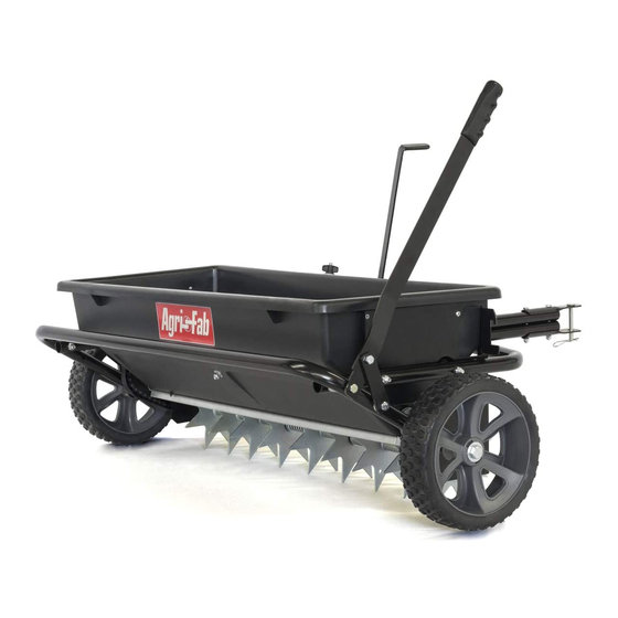
45-0543
32" POLY SPIKER/SPREADER
..................................................................4
ESPAÑOL..........................................................13
ENGLISH..........................................................6
FRANÇAIS.........................................................16
the fastest way to purchase parts www.speedepart.com
FORM NO. 45586 (11/05/2018)
Publicité
Table des Matières

Manuels Connexes pour SpeedEPart Agri-Fab 45-0543


Sommaire des Matières pour SpeedEPart Agri-Fab 45-0543
- Page 1 45-0543 32" POLY SPIKER/SPREADER ..............4 ESPAÑOL............13 ENGLISH............6 FRANÇAIS............16 the fastest way to purchase parts www.speedepart.com FORM NO. 45586 (11/05/2018)
- Page 2 PARTS FOR 32" POLY SPIKER/SPREADER MODEL 45-0543...
- Page 3 PARTS FOR 32" POLY SPIKER/SPREADER MODEL 45-0543 REF. PART NO. QTY. DESCRIPTION REF. PART NO. QTY. DESCRIPTION 47953 COVER, CHAIN 43081 WASHER, .375 X .875 X .083 24743 LEVER, FLOW CONTROL 1543-69 WASHER, NYLON 24747 BRACE, CENTER 43088 WASHER, .312 X .734 X .065 47931 HOPPER 47777...
- Page 4 RULES FOR SAFE OPERATIONS Any power equipment can cause injury if operated improperly or if the user does not understand how to operate the equipment. Exercise caution at all times, when using power equipment. • Wear eye and hand protection when handling and using • Read this owner's manual before attempting to assemble lawn chemicals. or operate the spiker/spreader. • Always begin with the transmission in first (low) gear and • Read the towing vehicle owner's manual and know how gradually increase speed as conditions permit. Maximum to operate the tractor before using the spiker/spreader towing speed - 10 M.P.H. attachment. • Do not drive too close to a creek or ditch and be alert • Do not allow anyone to ride on or sit on the spiker/ for holes and other hazards which could cause you to spreader. lose control of the tractor and spiker/spreader. • Never allow children to operate the tractor or spiker/ • Before operating the vehicle on any grade (hill) refer to spreader attachment.
- Page 5 1509-90 44215 44180 43224 43796 (13) 741-0249 47025 47189 (10) 45100 47810 44731 48115 43182 43012 43019 44101 43093 47623 46524 43088 43081 1543-69 R19212016 R19171616 NOT SHOWN FULL SIZE 47777 43848 24446 43943 47959 712-0421 24571 47960 47962 49449 46497 23520 47969...
-
Page 6: Tools Required For Assembly
ASSEMBLY TOOLS REQUIRED FOR ASSEMBLY • On the right side, assemble the handle brace bracket (2) 7/16" Wrenches (5) to the lift handle (9) using a 5/16" x 3/4" hex bolt (32) (2) 1/2" Wrenches and 5/16" nylock nut (27). See figure 2. (2) 3/4" or Adjustable Wrenches • Assemble the grip (45) onto the lift handle. (1) Screwdriver (1) Pliers Spike points are sharp. Exercise caution when handling and working near spike disks. FIGURE 2 • Attach a hitch tube to the right hand side of the hopper using two 5/16" x 2-1/4" hex bolts (16), 5/16" flat washers (35) and 5/16" nylock hex nuts (27). Assemble the bolts and washers from inside the hopper. Insert a tube plug (48). Repeat for the other side. • Insert a 5/16" x 3-1/2" hex bolt (14) through the transport tube (10), the lift handle (9), a spacer (42), and through the hitch tube. Secure with a 5/16 nylock nut (27). • Insert a 5/16" x 2" hex bolt (17) through the transport tube (10), two 5/16" flat washers (35), and the handle brace bracket. Secure with a 5/16" nylock nut (27). Tighten. See figure 3. FIGURE 1 FIGURE 3... - Page 7 • On the left side, insert a 5/16" x 3-1/2" hex bolt (14) through the upper hole on the transport tube (10), a spacer (42), and the hitch tube. Secure with a 5/16 nylock nut (27). Do not tighten yet. See figure 4. • Assemble a 1/2" x 4" hex bolt (13), a .531 washer (34), a wheel (6), a .531 washer (34), and a .5" jam nut (29). Finger tighten only. • Attach the wheel assembly to the transport tube using a 1/2" nylock jam nut (28). Repeat for the other side. See figure 6. FIGURE 4 • Fasten the hitch tubes together using two 1/4" x 2-3/4" hex bolts (15), hitch brackets (46), and 1/4" nylock hex nuts (26). Do not tighten yet. See figure 5. • Install the hitch pin (21) through the hitch brackets (46), and secure with a 3/32 hair cotter pin (25). FIGURE 6 FIGURE 5...
- Page 8 • Screw a 1/4" nylock hex nut (26) all the way onto the • Place the flow control lever into the slot in the hopper. flow control link (44). Assemble the ferrule (49) onto the See figure 8. link and then start a 1/4" nylock hex nut one or two turns • Place the center brace (3) into the hopper. Insert the onto the link. See figure 7. 1/4" x 1-1/4" hex bolt (19) through the center brace and • Assemble the ferrule (49) into the hole at the end of the front of the hopper. Assemble a 1/4" flat washer (37), the flow control lever (2) using a 1/4" nylock hex nut (26). the flow control lever and a 1/4" nylock hex nut (26) onto Tighten the nut, leaving it loose enough that the ferrule the bolt. Do not tighten yet. See figure 8. can pivot. See figure 7. • Insert the 1/4" x 3/4" hex bolt (30) through the center • Assemble the grip (43) onto the end of the flow control brace and the rear of the hopper. Assemble a 1/4" flat lever. See figure 7. washer (37) and 1/4" nylock hex nut (26) onto the bolt. Tighten both the front and rear bolts. See figure 8. FIGURE 8 • Insert the 5/16" x 1-3/4" carriage bolt (18) up through the slot and secure it with a nylon washer (36) and the FIGURE 7 plastic wing nut (39). See figure 9. • Move the lift handle into the locked position as shown in figure 9 and then tip the spreader back to rest on the wheels and the rear of the hopper.
- Page 9 • Move the flow control lever (2) as far as it will go to • Push two flanged bearings (22) into each of the drive the "OFF" position. Push the feed plate back as far as it disks (8). See figure 11. will go to the closed position. See figure 10. • Place a nylon washer (36) onto the bent end of the flow control link (44) and then insert the link into the feed plate bracket. Secure it with a 3/32" x 3/4" cotter pin (24). See figure 10. • Tighten the lower 1/4" nylock hex nut (26) until it touches the bottom of the ferrule, then tighten the upper 1/4" nylock hex nut (26) until it is snug against the top of the ferrule. See figure 10. • Hook the open end of the spring (40) into the feed plate. Place the closed end of the spring onto the end of the hex bolt in the flow control lever. Secure it with a 1/4" nylock hex nut (26). See figure 10. FIGURE 11 • Open and close the feed plate using the flow control lever. Check to make sure the feed plate is closed completely when the lever is in the "OFF" • Push a flanged bearing (22) into each of the seven position. If the feed plate does not close completely, spike disks (7), from the side shown in figure 12. adjust the 1/4" nylock hex nuts (26) on the flow con- trol link (44). See figure 10. FIGURE 12 • Press flanged bearings (22) into both of the end plates. See figure 13. • Place the 1/4" thick spacer (50) onto the spike disk shaft (12) and then insert the shaft through the flanged bearing (22) in the left hand end plate. See figure 13.
- Page 10 • Place a short spacer tube (41), a drive disk (8), a 5/8" • Place a 5/8" flat washer (33), the compression spring flat washer (33), another drive disk and a second 5/8" flat (38) and another 5/8" flat washer onto the shaft. See washer onto the shaft. Fit the short spacer tube onto the figure 16. flanged bearing in the end plate. See figure 14. FIGURE 16 FIGURE 14 • Place two spike disks (7), separated by a long spacer tube (20), onto the shaft. Fit the long spacer tube onto the ends of the flanged bearings in the disks. See figure 17. • Place two spike disks (7), separated by a long spacer tube (20), onto the shaft. Fit the long spacer tube onto the ends of the flanged bearings in the disks. See figure 15. FIGURE 17 • Place two 5/8" flat washers (33) separated by a long spacer tube (20) onto the shaft. See figure 18. FIGURE 18 FIGURE 15...
- Page 11 • Place two spike disks (7), separated by a long spacer tube (20), onto the shaft. Fit the long spacer tube onto the • Place one or two 5/8" flat washers (33) onto the end ends of the flanged bearings in the disks. See figure 19. of the spike disk shaft and secure the shaft with a 1/8" x 1-1/2" cotter pin (23) by spreading the ends of the cotter pin. See figure 22. • Fasten the two drive disks to the shaft using two 1/8" x 1-1/2" cotter pins (23) by spreading the ends of the cotter pin. See figure 22. FIGURE 19 • Place two 5/8" flat washers (33) separated by a long spacer tube (20) onto the shaft. See figure 20. FIGURE 22 • Remove connecting link from chain and assemble the chain (47) onto the two sprockets on the left side of the hopper. Fasten the ends of the chain together using the connecting link. See figure 23. • Place the chain cover over the chain and fasten it to FIGURE 20 the hopper end plate using two self tapping screws (31). See figure 23. • Place a spike disk (7) and a short spacer tube (41) onto the shaft. Fit the short spacer tube onto the ends of the flanged bearings in the spike disk and in the end plate. Push the shaft on through the flanged bearing in the end plate. See figure 21. CONNECTING LINK FIGURE 21 FIGURE 23...
- Page 12 OPERATION SETTING CHART Flow Rate Setting MATERIAL TYPE At 3 M.P.H. HOW TO USE YOUR SPIKER/SPREADER Fertilizer Granular / Pelleted 5-6 / 6-7 1. Refer to the instruction label on the material package and to the instruction decal on your spreader to help Grass Seed Fine / Coarse 5-6 / 7-8 determine the proper spreader setting and application 3 M.P.H. is equivalent to traveling 100 feet in 23 seconds. rate. A lso see the Setting Chart on this page for a general range of settings for commonly used materials.
-
Page 13: Instrucciones De Ensamblaje
ESPAÑOL REGLAS PARA UNA OPERACIÓN SEGURA Cualquier equipo motriz puede causar lesiones si no se opera correctamente o si el usuario no entiende la forma de operar el equipo. Tenga siempre cuidado cuando use un equipo motriz. • Lea este manual de instrucciones con mucho cuidado antes • Use protección para sus ojos y sus manos cuando maneje y de tratar de armar u operar este surcador-esparcidor. aplique productos químicos para el césped. • Lea el manual de instrucciones del tractor y conozca bien la • Siempre comience con la transmisión en primera (baja) forma de operar el tractor antes de usar este equipo surcador- velocidad y aumente la velocidad gradualmente como lo esparcidor. permitan las condiciones. La velocidad máxima de remolque • No permita que nadie se monte ni se siente sobre el surcador- es 10 M.P.H. (16 kilómetros por hora). esparcidor. •... - Page 14 • Coloque un tubo separador corto (41), un disco de accionamiento (8), una arandela plana de 5/8" (33), otro disco • Coloque el anclaje central (3) en la tolva. Inserte un perno de accionamiento y una segunda arandela plana de 5/8" en el hexagonal de 1/4" x 1-1/4" (19) por el anclaje central y la parte eje. Coloque el tubo separador corto en el cojinete embridado frontal de la tolva. Colo-que una arandela plana de 1/4" (37), de la placa terminal. Consulte la figura 14. la palanca de control de flujo y una tuerca hexagonal de se- guridad de nylon de 1/4" (26) en el perno. No apriete todavía. • Coloque dos discos surcadores (7) separados por un tubo Consulte la figura 8.
- Page 15 ESPAÑOL OPERACIÓN CUADRO DE AJUSTE FORMA USAR EQUIPO SURCADOR- MATERIAL TIPO Ajuste de la cantidad de flujo a 3 M.P.H. (4.8 kph) ESPARCIDOR Fertilizante Granular / En forma 5 - 6 / 6 - 7 de pelotillas 1. Lea la etiqueta de instrucciones en el paquete de materiales y la calcomanía de instrucciones en el esparcidor para Semilla Fina / Gruesa 5 - 6 7 - 8 determinar el ajuste apropiado del esparcidor y la velocidad...
-
Page 16: Règles De Sécurité D'utilisation
FRANÇAIS RÈGLES DE SÉCURITÉ D’UTILISATION Tout équipement à moteur peut causer des blessures s’il est mal utilisé ou si l’utilisateur ne sait pas comment l’utiliser. Il faut faire attention en permanence pour utiliser l’équipement à moteur. et utiliser les produits chimiques de pelouse. • Lire ce manuel du propriétaire avant d’essayer d’assembler • Commencer toujours avec la boîte de vitesse en première ou d’utiliser la cramponneuse/répandeuse. (vitesse basse) et augmenter graduellement la vitesse selon • Lire le manuel du propriétaire du véhicule remorqueur et bien les conditions. Vitesse maximale de remorquage : 16 km/h (10 savoir comment utiliser le tracteur avant d’utiliser l’accessoire milles/hr). de cramponneuse/répandeuse. • Ne pas conduire trop près d’un ruisseau ou un fossé et faire • Ne permettre à personne de monter ou de s’asseoir sur la attention aux trous et autres dangers qui pourraient causer cramponneuse/répandeuse. - Page 17 • Assembler l’embout (43) sur l’extrémité du levier de • Placer un court tube d’espacement (41), un disque commande de débit. Voir figure 7. d’entraînement (8), une rondelle plate de 5/8 po (33), un • Placer le levier de commande dans la fente de la trémie. Voir autre disque d’entraînement et une deu-xième rondelle plate figure 8. de 5/8 po sur l’arbre. Ajuster le court tube d’espacement sur le palier avec bride dans la plaque d’extrémité. Voir figure 14. • Placer le renfort central (3) dans la trémie. Insérer un boulon à tête hexagonale de 1/4 po x 1 1/4 po (19) dans le renfort • Placer sur l’arbre deux disques éperons (7) sépa-rés central et le devant de la tré-mie. Assembler une rondelle par un long tube d’espacement (20). Ajuster le long tube plate de 1/4 po (37), le levier de commande de débit et un...
-
Page 18: Fonctionnement
FRANÇAIS FONCTIONNEMENT TABLEAU DE RÉGLAGE MATÉRIAU TYPE Réglage de débit à COMMENT UTILISER CRAMPONNEUSE/ 5 km/h (3 milles/hr) RÉPANDEUSE Fertilisant Granulaire / à boulettes 5-6 / 6-7 1. Se reporter à l’étiquette d’instructions sur l’emballage du matériau et à l’autocollant d’instructions sur la répandeuse Semence Fine / lourde 5-6 / 7-8 d’herbe... - Page 19 NOTES...
-
Page 20: Repair Parts
REPAIR PARTS Agri-Fab, Inc. 303 West Raymond Sullivan, IL. 61951 217-728-8388 www.agri-fab.com...