Publicité
Les langues disponibles
Les langues disponibles
Bedienungsanleitung / Operation Manual / Mode d'emploi / Manual de instrucciones
APS 60 - APS 70 - APS 120
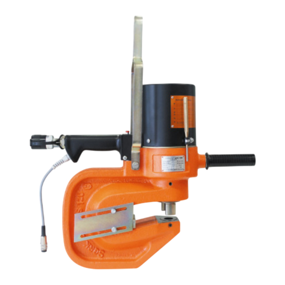
Hydraulik-Lochstanze
Hydraulic Hole Punch
Poinçonneuse hydraulique
Punzonadora hidráulica
Artikel Nr. 23001 – 23002 - 23004 / Article No. 23001 – 23002 - 23004 /
Articles No. 23001 – 23002 – 23004 / Nº de artículo 23001 – 23002 - 23004
1
Publicité
Table des Matières

Manuels Connexes pour ALFRA APS 60


Sommaire des Matières pour ALFRA APS 60
- Page 1 Bedienungsanleitung / Operation Manual / Mode d’emploi / Manual de instrucciones APS 60 - APS 70 - APS 120 Hydraulik-Lochstanze Hydraulic Hole Punch Poinçonneuse hydraulique Punzonadora hidráulica Artikel Nr. 23001 – 23002 - 23004 / Article No. 23001 – 23002 - 23004 /...
- Page 2 Inhaltsverzeichnis / Contents / Table des matières / Índice Allgemeine Sicherheitsbestimmungen, Sicherheitshinweise, Bestimmungsgemäße Verwendung, Inbetriebnahme Funktionsbeschreibung, Technische Daten, Belastbarkeit lesen und Seite 3 und Auswahl der Werkzeuge, Inbetriebnahme, Wartung und aufbewahren! Reparatur, Garantie, Konformitätserklärung, Zubehör, Werkzeuge, Pumpen, Ersatzteillisten. General safety specifications, safety information, intended Read before use, functional description, technical data, carrying capacity initial operation...
-
Page 3: Symbolerklärung
Allgemeine Sicherheitsbestimmungen Dieses Kapitel zeigt den Benutzern von ALFRA Produkten und Dritten alle grundlegenden Sicherheits- bestimmungen auf, die unbedingt zu beachten sind. Diese Sicherheitsbestimmungen müssen in allen Punkten gelesen und verstanden werden, bevor die Maschine in Betrieb genommen wird. Das mit der Tätigkeit an der Maschine beauftragte Personal muss vor Inbetriebnahme die Betriebsanleitung gelesen und verstanden haben. -
Page 4: Sicherheitshinweise
Sicherheitshinweise Bringen Sie niemals Ihre Finger in den Stanzbereich! Tragen Sie bei allen Stanzarbeiten an der Maschine eine Schutzbrille und einen Gehörschutz! Tragen Sie bei allen Stanzarbeiten an der Maschine Schutzhandschuhe! Auch Personen, die sich in der Nähe der Maschine befinden, müssen eine Schutzbrille tragen! Bei allen Wartungs-, Installations- und Reinigungsarbeiten muss das Gerät vom Stromnetz getrennt werden! Die Maschine ist nur gemäß... - Page 5 • Die APS Stanzbügel sind für das Stanzen von metallischen Halbzeugen bis zu mittleren Festigkeiten geeignet. Eine detailliertere Beschreibung entnehmen sie dem Abschnitt „Belastbarkeit und Auswahl der Werkzeuge“. Die Stanzbügel APS 60-70-120 sind standardmäßig nicht geeignet zum Stanzen von hochfesten Werkzeugstählen, nicht rostendem Material oder Kesselblechen.
-
Page 6: Funktionsbeschreibung
Funktionsbeschreibung Die ALFRA APS 60, 70 und 120 Stanzbügel sind mobile Arbeitsgeräte zum Einbringen von Rund- und Langlöchern in metallische Halbzeuge. Über den integrierten Hydraulikzylinder werden bei max. 700 bar Druck die erforderlichen Stanzkräfte bereitgestellt, mit denen die Halbzeuge gemäß Abschnitt „Belastbarkeit & Auswahl der Werkzeuge“... - Page 7 Lieferumfang Zum Lieferumfang der ALFRA APS Stanzbügel gehören standardmäßig folgende Komponenten: • ein APS Stanzbügel • ein 5 m Hydraulikschlauch • ein Werkzeugset bestehend aus Stempel und Matrize: Loch-Ø 14 mm bei APS 60 Loch-Ø 18 mm bei APS 70 Loch-Ø...
- Page 8 Beim Einsatz von schnell arbeitenden, mechanischen Pressen findet sie jedoch immer noch Anwendung, weil der Vorgang schlagartig erfolgt und der Stempel dabei bis auf das Äußerste beansprucht wird. Bei unseren ALFRA APS-Stanzbügeln wird der Stanzprozess jedoch langsamer und sanft ausgeführt. In diesem Fall können auch Löcher gestanzt werden, deren Durchmesser geringer ist als die Stärke des zu stanzenden Materials.
- Page 9 Warum ist mein Stempel gebrochen? • S/D-Durchmesserverhältnis stimmt nicht. • Das zu stanzende Material liegt nicht gerade, sondern verkantet auf der Matrize. • Beim Stanzvorgang wird der Stanzbügel bzw. das Material stark bewegt. • Wenn der Abstreifer beschädigt oder in der Höhe nicht richtig eingestellt ist, kann sich das Material beim Rückzug des Stempels verkanten.
- Page 10 1,00 1,09 1,34 1,51 1,28 1,49 1,70 1,91 Faktor (Stahl X/S233) Maximale Stanzkräfte: APS 60: = 220 kN APS 70: = 310 kN APS 120: F = 440 kN Beispiel 1 Beispiel 2 Stanzbügel APS 70, F = 310 kN Stanzbügel APS 70, F...
- Page 11 Inbetriebnahme Anschluss der Hydraulikpumpe Als Antrieb empfehlen wir Alfra-Hydraulik-Pumpe SC 05 II-B oder Alfra-Hydraulik-Pumpe SC 17. 1. Verbinden Sie die ausgewählte Hydraulikpumpe und den Stanzbügel mit dem mitgelieferten Hydraulikschlauchpaket. Die Kupplung muss fest verschraubt werden. Die Schutzkappen sollten erst unmittelbar vor dem Zusammenstecken entfernt werden.
- Page 12 Werkzeugmontage für Rundloch Zuerst die Matrize einsetzen. Matrize 1. Lösen Sie die beiden Madenschrauben am Matrizenbett. 2. Setzen Sie die Matrize mit der blanken Oberfläche (mit dem kleineren Durchmesser) nach oben in das Matrizenbett. 3. Die beiden Madenschrauben anschließend anziehen. 4.
- Page 13 Werkzeugmontage für Langloch (nur bei APS 70 und APS 120) Zuerst die Matrize einsetzen. Matrize 1. Lösen Sie die Madenschraube unten an beiden Seiten des Stanzkörpers. Setzen Sie die saubere Matrize so ein, dass die Seite mit dem kleineren Lochdurchmesser (blanke Seite) nach oben zeigt. 2.
- Page 14 Lieferbare Stempel und Matrizen Lieferbar sind verschiedene Stempel und Matrizen. Bitte entnehmen Sie diese dem Katalog bzw. dem Anhang und geben Sie bei der Bestellung die Artikelnummer an. Beim Stanzen von Trägern mit schrägem Flansch sind die entsprechenden 5° abgeschrägten Matrizen zu verwenden. Das Stanzen von schrägen Flanschen ist nur mit dem Modell APS 70 und APS 120 möglich.
- Page 15 Stanzzeit verlängert sich. Zum Entlüften des Stanzbügels gehen Sie wie folgt vor: 1. Schrauben Sie die 8 mm Schraube (Teil 36) aus dem Grundkörper (siehe Explosionszeichnung) 2. Drehen Sie die dahinterliegende Ablassschraube (Teil 37 bei APS 60 und 70 / Teil 21 bei APS 120) eine Drehung heraus.
- Page 16 • Ersatzteil-Bezeichnung • Menge der gewünschten Teile Mechanische und elektrische Arbeiten an APS-Stanzen dürfen nur von Fachpersonal von ALFRA oder von Fachkräften, nach Rücksprache mit unserem Fachpersonal, ausgeführt werden. Allen anderen Personen ist es untersagt Reparatur- oder Änderungsarbeiten an dem Gerät auszuführen.
-
Page 17: Eg-Konformitätserklärung
ALFRA Alfred Raith GmbH 2. Industriestraße 10 68766 Hockenheim dass bei Auslegung und Bau der Maschine ALFRA Press Modell APS 60, APS 70, APS 120, auf die sich diese Erklärung bezieht, folgende Richtlinien und Normen angewandt wurden: Richtlinie 2006/42/EG EN 60204-1 EN ISO 12100 Hockenheim, 01.10.2011... - Page 21 Wir empfehlen folgenden Antrieb:...
- Page 22 General Safety Specifications This chapter provides users of ALFRA products and third parties with all basic safety specifications, which must be observed. The safety specifications must be read and understood in all points before the machine is operated. Persons responsible for operating the machine must have read and understood the operations manual before initial operation.
- Page 23 Safety Information Never place your finger in the punching area! Warning Always wear protective goggles and ear protection when operating the machinery! Always wear protective gloves when operating the machinery! Even people who are near the machine must wear protective goggles! During all maintenance, installation and cleaning work the equipment must be disconnected from the mains.
- Page 24 • The APS punching unit should only be used for its intended purpose. Deviation from the operation manual of the APS unit, technical changes or modifications, as well as use of non-original spare parts reduce the level of safety. ALFRA takes no responsibility for this and waives any guarantee.
- Page 25 Functional Description The ALFRA APS 60, 70 and 120 punching units are mobile pieces of equipment used to create round and long holes in metallic semi-finished products. Through the integrated hydraulic cylinders half-finished products can be processed using the required punch force provided at maximum 700 bar of pressure, in accordance with the section "Carrying Capacity &...
- Page 26 Delivery The following standard components are included with the ALFRA APS punching unit: • an APS punching unit • a 5 m long hydraulic hose • a tool set of punches and die-plates: Hole-Ø 14 mm with APS 60 Hole-Ø 18 mm with APS 70 Hole-Ø...
- Page 27 However with fast-acting, mechanical presses, it is still used because the process is very abrupt and in the process the punch will be used to full capacity. However with our ALFRA APS punching unit the punching process is slower and more smoothly executed. In this case holes can be punched with a diameter smaller than the thickness of the material to be punched.
- Page 28 Why is my punch broken? • S/D diameter ratio is not correct. • The material to be punched is not straight but tilted in the die-plate. • When punching the punch or material is suddenly moved. • If the wiper is damaged or not properly adjusted in height, the material can become jammed during retraction of the punch.
- Page 29 Operating Range of the APS punching unit for round holes with S233 Conversion factor of S233 for the processing of various materials. max [N/mm²] (sheet) S233 S275 S355 E335 τmax = 0,85 ⋅ R max [N/mm²] Factor (Steel X / S233) 1.00 1.09 1.34...
- Page 30 Initial Operation Connecting the hydraulic pump 1. Connect the selected hydraulic pump and the punching unit with the supplied cable assembly. The coupling must be firmly bolted. The protective caps should not be removed until immediately before assembly. 2. Plug the 5-pin cable connection into the socket provided on the pump and on the punch. 3.
- Page 31 Tool Assembly for round punch First insert the die. 1. Loosen both the grub screws on the die bed. 2. Place the die with the blank surface (with the small diameter) facing upwards on the die bed. 3. Then tighten the two grub screws. 4.
- Page 32 Tool Assembly for long hole (only with APS 70 and APS 120) First insert the die. 1. Loosen the grub screws on both sides of the punch body. Place the clear die-plates so that the side with the smaller hole diameter (blank side) is facing upwards. 2.
- Page 33 Available punches and dies Different punches and dies are available. Please refer to the catalogue or the appendix and give the article numbers when ordering. When punching carriers with an inclined flange the corresponding 5° inclined dies are to be used. Punching inclined flanges is only possible with the APS 70 and APS 120 models. Starting the APS punch together with the pumps 1.
- Page 34 1. Unscrew the 8 mm screws (part 36) from the body (see exploded diagram) 2. Turn the underlying drain plug (part 37 with APS 60 & 70 / part 21 with APS 120) one rotation. 3. Press the black "START" button.
- Page 35 Mechanical and electrical work on APS punching units may only be carried out by specialists from ALFRA or by specialists who have consulted with our specialist personnel. All other persons are prohibited from carrying out repair work or alteration work on the equipment. Spare parts must correspond to the specific technical requirements of the manufacturer.
- Page 36 2. Industriestraße 10 68766 Hockenheim hereby declare that in the design and construction of the machine ALFRA Press Modell APS 60, APS 70, APS 120 to which this declaration applies, the following guidelines have been applied: Guideline 2006/42/EG EN 60204-1 EN ISO 12100 Hockenheim, 01.
- Page 40 We recommend following drive system:...
- Page 41 Directives générales de sécurité Ce chapitre montre aux utilisateurs des produits ALFRA et aux tiers toutes les directives générales de sécurité qui doivent absolument être respectées. Ces directives de sécurité doivent être lues point par point et doivent être comprises avant que la machine soit prise en service. Le personnel chargé du maniement de la machine doit avoir lu et compris le mode d'emploi avant la mise en service de la machine.
- Page 42 Consignes de sécurité Ne saisissez jamais avec vos mains la zone de poinçonnage! Avertissement Portez des lunettes de protection et un protège-ouïes lors de tous les travaux de poinçonnage à la machine! Portez toujours des gants de protection lors des travaux de poinçonnage! Les personnes se trouvant aux environs de la machine doivent également porter des lunettes de protection! Lors de tout travail de maintenance, d'installation et de nettoyage, l'appareil doit être séparé...
- Page 43 Vous trouvez une description détaillée dans le paragraphe "portance et sélection des outils". Dans leur version standard, les étriers de poinçonnage APS 60-70-120 ne sont pas appropriés au poinçonnement d'acier à outil à haute résistance, de matériel inoxydable ou de tôles pour chaudières.
- Page 44 Description des fonctions Les étriers de poinçonnage ALFRA APS 60, 70 et 120 sont des appareils de travail mobiles destinés à faire des trous ronds et en longueur dans des produits semi-finis métalliques. Par le cylindre hydraulique intégré, avec une pression maximale de 700 bars, les forces de poinçonnage nécessaires sont mises à...
- Page 45 • un étrier de poinçonnage APS • un tube hydraulique de 5 m de long • un set d'outils composé du poinçon et de la matrice : Trou-Ø 14 mm avec l'APS 60 Trou-Ø 18 mm avec l'APS 70 Trou-Ø 22 mm avec l'APS 120 •...
- Page 46 Chez nos étriers de poinçonnage ALFRA APS, le procédé de poinçonnage est cependant exécuté plus lentement et plus doucement. Dans ce cas, des trous, dont le diamètre est inférieur à la résistance du matériel à poinçonner, peuvent également être poinçonnés.
- Page 47 Pourquoi mon poinçon s'est-il cassé? • La relation de diamètre S/D n'est pas exact. • Le matériel à poinçonner n'est pas positionné de façon droite, mais de façon déversée sur la matrice. • Pendant le procédé de poinçonnage, le matériel, respectivement l'étrier de poinçonnage a fortement bougé. •...
- Page 48 Domaine de travail des étriers de poinçonnage APS pour trous ronds chez acier S233 Facteur de conversion de S233 pour le traitement de matériaux différents S233 S275 S355 E335 max [N/mm²] (tôle) τmax = 0,85 ⋅ R max [N/mm²] Facteur (Acier X/S233) 1,00 1,09 1,34...
- Page 49 Mise en service Raccordement de la pompe hydraulique 1. Raccordez la pompe hydraulique sélectionnée à l'étrier de poinçonnage à l'aide du paquet de tube hydraulique livré avec. L'accouplement doit être bien serré. Les capuchons protecteurs doivent être enlevés uniquement juste avant le raccordement. 2.
- Page 50 Montage d'outils pour trou rond D’abord emmancher la matrice. Matrice 1. Desserrez les deux vis sans tête au lit de matrice. 2. Posez la matrice avec la surface claire (avec le plus petit diamètre) vers le haut dans le lit de matrice. 3.
- Page 51 Montage d'outils pour trou en longueur (seulement chez APS 70 et APS 120) D’abord emmancher la matrice. Matrice 1. Desserrez la vis sans tête en bas des deux côtés du corps de la poinçonneuse. Insérez la matrice propre de façon à ce que le côté avec le diamètre de trou inférieur (côté clair) montre vers le haut. 2.
- Page 52 Poinçons et matrices livrables Différents poinçons et différentes matrices sont livrables. Vous les trouverez dans ce catalogue, resp. son annexe et veuillez indiquer le numéro d'article lors de la commande. En estampant des supports avec bride inclinée, les matrices appropriées inclinées de 5° doivent être utilisées. L'emboutissement de brides inclinées est uniquement possible avec les modèles APS 70 et APS 120.
- Page 53 1. Dévissez la vis de 8 mm (pièce 36) du corps de base (voir dessin d'explosion). 2. Dévissez la vis de purge qui se trouve derrière (pièce 37 chez APS 60 & 70 / pièce 21 chez APS 120) d'une rotation.
- Page 54 Des travaux mécaniques ou électriques aux poinçonneuses APS doivent uniquement être exécutés par du personnel spécialisé ALFRA ou par du personnel spécialisé, après discussion préalable avec notre personnel spécialisé. Il est interdit à toute autre personne d'effectuer des travaux de réparation ou de transformation sur l'appareil.
- Page 55 ALFRA Alfred Raith GmbH 2. Industriestraße 10 68766 Hockenheim déclarons que dans la conception et la construction de la machine ALFRA Press APS 60, APS 70, APS 120 à laquelle cette déclaration s’applique, les directives suivantes ont été appliquées: Directive 2006/42/EG EN 60204-1 EN ISO 12100 Hockenheim, 1 Oct.
- Page 59 Nous recommandons la transmission suivante:...
- Page 60 Prescripciones generales de seguridad Este capítulo indica a los usuarios de los productos ALFRA y a terceros las prescripciones de seguridad básicas que es imprescindible respetar. Leer y comprender todos los puntos de estas prescripciones de seguridad antes de poner en marcha la máquina. El personal encargado de las tareas en la máquina debe haber leído y comprendido el manual de instrucciones antes de la puesta en marcha.
- Page 61 Indicaciones de seguridad ¡Nunca coloque sus dedos en la zona de punzonado! advertencia ¡Durante todos los trabajos de punzonado en la máquina utilice lentes de protección y protectores auditivos! ¡Utilice guantes en todos los trabajos punzonado en la máquina! ¡Incluso las personas que se encuentran cerca de la máquina deben usar lentes de protección! ¡Desconectar el aparato de la red eléctrica para realizar todos los trabajos de mantenimiento, instalación y limpieza! ¡Operar la máquina sólo en función a las indicaciones de este manual de instrucciones!
- Page 62 Podrá encontrar una descripción detallada en el capítulo "Capacidad de carga y selección de las herramientas". Los arcos de punzonado APS 60-70-120 de modo estándar no son aptos para el punzonado de acero para herramientas de alta resistencia, material inoxidable o chapa para calderas.
- Page 63 "Capacidad de carga & selección de herramientas". La presión hidráulica se produce en una unidad de bomba externa (ALFRA SC05 IIB o ALFRA SC 17) y se transmite mediante un tubo flexible a la conexión (6) en el arco de punzonado. El aceite hidráulico produce una presión sobre el émbolo y el vástago del émbolo y mueve de esa manera la herramienta (punzón).
- Page 64 Volumen de suministro Pertenecen al volumen de suministro del arco de punzonado ALFRA ASP en forma estándar los siguientes componentes: • un arco de punzonado APS • un tubo flexible hidráulico de 5 m • un set de herramientas compuesto por un punzón y una estampa: Orificio Ø...
- Page 65 Pero en el caso de nuestros arcos de punzonado ALFRA APS el proceso de punzonado se realiza en forma más lenta y suave. En este caso también se puede punzonar orificios cuyo diámetro es menor al espesor del material a punzonar.
- Page 66 ¿Por qué se quebró mi punzón? • La relación de diámetro S/D no es correcta. • El material a punzonar no se encuentra en posición recta sino ladeado sobre la estampa. • En el proceso del punzonado el arco de punzonado o el material se mueven fuertemente. •...
- Page 67 Zona de trabajo de los arcos de punzonado APS para punzones redondos en acero S233 Factor de conversión de S233 para el procesamiento de diferentes materiales. ² S233 S275 S355 E335 [N/mm ] (chapa) ² = 0,85 [N/mm τ ⋅ 1,00 1,09 1,34...
- Page 68 Puesta en marcha Conexión de la bomba hidráulica 1. Conecte la bomba hidráulica seleccionada y el arco de punzonado con paquete de tubos flexibles hidráulicos suministrado. El acoplamiento debe estar correctamente atornillado. Las caperuzas protectoras recién deben removerse antes de colocarlas. 2.
- Page 69 Montaje de las herramientas para punzones redondos Primero injertar la estampa. Estampa 1. Suelte ambos tornillos prisioneros en el montante de la estampa. 2. Coloque la estampa con la superficie desnuda (con el diámetro pequeño) hacia arriba en el montante de la estampa.
- Page 70 Montaje de las herramientas para punzones ovalados (sólo en APS 70 y APS 120) Primero injertar la estampa. Estampa 1. Suelte el tornillo prisionero abajo en ambos lados del cuerpo de punzonado. Coloque una estampa limpia de modo tal que el lado con el diámetro de punzón más pequeño (lado desnudo) indique hacia arriba. 2.
- Page 71 Punzones y estampas suministrables Se puede suministrar diferentes punzones y estampas. Éstos se encuentran en el catálogo o en el anexo, por favor extráigalos de allí y en el pedido indique el número de artículo. En el punzonado de portantes con brida inclinada se deben emplear las correspondientes estampas ladeadas a 5º.
- Page 72 1. Atornille el tornillo de 8 mm (parte 36) del cuerpo base (véase vista desarrollada) 2. Desatornille el tornillo de purga que se encuentra detrás con un giro hacia fuera (parte 37 en APS 60 y 70 / parte 21 en APS 120).
- Page 73 Los trabajos mecánicos y eléctricos en las punzonadoras APS sólo deben ser realizadas por personal técnico de ALFRA o por personal técnico con consentimiento de nuestro personal técnico. Está prohibida la realización de trabajos de reparación o modificaciones en el aparato para cualquier otra persona.
- Page 74 2. Industriestraße 10 68766 Hockenheim que en el diseño y construcción de la máquina ALFRA Press Modell APS 60, APS 70, APS 120 a la que esta declaración es válida, las siguientes directrices y normas que se aplican son: Directrice 2006/42/EG...
- Page 78 Recomendamos el siguiente accionamiento:...
- Page 79 Ersatzteilliste / Spare part list / Liste de pièces de rechange / Lista de piezas de recambio APS 60 - Art.Nr.: 23001...
- Page 81 Stückliste / Part list APS 60 - 23001 Art.-Nr. Menge Benennung Description Bemerkung / Remark Prod.-No. DIN7985-M5x6-4.8 Flachkopfschraube Flat head screw ISO 7045-M5x6-4.8 23001-003 Schutzhaube Protection cap Sechskantmutter Hexagon nut 23002-004A ISO8673-M24x2-8: DIN934 nachgearbeitet overworked 23002-005A Druckplatte Pressure plate 23002-006A...
- Page 82 Stückliste / Part list APS 60 - 23001 Art.-Nr. Menge Benennung Description Bemerkung / Remark Prod.-No. 23004-051 Handgriffkabel Flexible control conduit LiYY 5x0,5² 500mm lg 03200-057A Kabelstecker 5-pol. 5-Way Plug 680 09 0313 00 05 23002-053 O-Ring O-ring 42x3 NBR 70...
- Page 83 Liste des pièces / Lista de piezas APS 60 - 23001 No. d'art. Quantité No. de prod./ Dénomination Denominación Remarque / Notas Cantidad Nº de artículo pos. Nº de producto DIN7985-M5x6-4.8 Vis à tête plate Tornillo avellanado ISO 7045-M5x6-4.8 23001-003 Capot de protection Caperuza de protección...
- Page 84 Liste des pièces / Lista de piezas APS 60 - 23001 No. d'art. Quantité No. de prod./ Dénomination Denominación Remarque / Notas Cantidad Nº de artículo pos. Nº de producto Câble poignée 23004-051 Cable del asidero LiYY 5x0,5² 500mm lg manuelle Fiche de câble à...
- Page 85 Ersatzteilliste / Spare part list / Liste de pièces de rechange / Lista de piezas de recambio APS 70 - Art.Nr.: 23002...
- Page 87 Stückliste / Part list APS 70 - 23002 Menge Art.-Nr. Benennung Description Bemerkung / Remark Prod.-No. DIN7985-M5x6-4.8 Flachkopfschraube Flat head screw ISO 7045 - M5 x 6 - 4.8 23002-003 Schutzhaube Protection cap Sechskantmutter 23002-004A ISO8673-M24x2-8: DIN934 nachgearbeitet 23002-005A Druckplatte Pressure plate 23002-006A Elastomerfeder...
- Page 88 Stückliste / Part list APS 70 - 23002 Menge Art.-Nr. Benennung Description Bemerkung / Remark Prod.-No. Flexible control 23004-051 Handgriffkabel LiYY 5x0,5² 500mm lg conduit 03200-057A Kabelstecker 5-pol. 5-Way Plug 680 09 0313 00 05 23002-053 O-Ring O-ring 42x3 NBR 70 23002-054 Niederhalter Hold down...
- Page 89 Liste des pièces / Lista de piezas APS 70 - 23002 No. d'art. Quantité No. de prod./ Dénomination Denominación Remarque / Notas Cantidad Nº de artículo pos. Nº de producto DIN7985-M5x6-4.8 Vis à tête plate Tornillo avellanado ISO 7045 - M5 x 6 - 4.8 23002-003 Capot de protection Caperuza de protección...
- Page 90 Liste des pièces / Lista de piezas APS 70 - 23002 No. d'art. Quantité No. de prod./ Dénomination Denominación Remarque / Notas Cantidad Nº de artículo pos. Nº de producto Câble poignée 23004-051 Cable del asidero LiYY 5x0,5² 500mm lg manuelle Fiche de câble à...
- Page 91 Ersatzteilliste / Spare part list / Liste de pièces de rechange / Lista de piezas de recambio APS 120 - Art.Nr.: 23004...
- Page 93 Stückliste / Part list APS 120 - 23004 Menge Art.-Nr. Benennung Description Bemerkung / Remark Prod.-No. DIN7985-M5x6-4.8 Flachkopfschraube Flat head screw ISO 7045-M5x6-4.8 23004-003A Schutzhaube Protection cap DIN934-M24x2-8: Sechskantmutter Hexagon nut /Fine ISO 8673-M24x2-8: 23004-005A Druckplatte Pressure plate (ab / from N° :280) (ab / from N°...
- Page 94 Stückliste / Part list APS 120 - 23004 Menge Art.-Nr. Benennung Description Bemerkung / Remark Prod.-No. 23004-062B Rohrschelle gummiert Clamp DIN7985-M5x10-4.8 Flachkopfschraube Flat head screw ISO7045-M5x10-4.8 23004-063 Ring Ring DIN472-68x2,5 Sicherungsring Lock washer DIN 472 - 68 x 2,5 23004-065A Kabel Cable FLEX-JZ 3x0,75²...
- Page 95 Liste des pièces / Lista de piezas APS 120 - 23004 No. d'art. Quantité No. de prod./ Dénomination Denominación Remarque / Notas Cantidad Nº de artículo pos. Nº de producto DIN7985-M5x6-4.8 Vis à tête plate Tornillo avellanado ISO 7045-M5x6-4.8 Caperuza de 23004-003A Capot de protection protección...
- Page 96 Liste des pièces / Lista de piezas APS 120 - 23004 No. d'art. Quantité No. de prod./ Dénomination Denominación Remarque / Notas Cantidad Nº de artículo pos. Nº de producto Collier de tuyau Abrazadera de tubo 23004-062B gommé engomada DIN7985-M5x10-4.8 Vis à...
- Page 104 Alfred Raith GmbH Tel. 06205-3051-0 2. Industriestr. 10 Fax 06205-3051-150 D-68766 Hockenheim Internet: www.alfra.de E-mail: info@alfra.de...