Publicité
Liens rapides
MINOTAUR
MSR127R-MSR127T
Installation Instructions
(b)
RETAIN THESE INSTRUCTIONS
Installation must be in accordance with the following steps and must be carried
out by suitably competent personnel.
This device is intended to be part of the safety related control system of a
machine. Before installation, a risk assessment should be performed to determine
whether the specifications of this device are suitable for all foreseeable
operational and environmental characteristics of the machine to which it is to be
fitted.
At regular intervals during the life of the machine check whether the
characteristics foreseen remain valid.
Guardmaster cannot accept responsibility for a failure of this device if the
procedures given in this sheet are not implemented or if it is used outside the
recommended specifications in this sheet.
Exposure to shock and/or vibration in excess of those stated in IEC 68 part: 2-6/7
should be prevented.
Adherence to the recommended inspection and maintenance instructions forms
part of the warranty.
Mode of Operation
(c)
The dual-channel operation shown in wiring examples 5 and 6 includes crossfault
monitoring between both E-stop circuits. That means in case of shorts between the
two E-stop channels the MSR127 will de-energise the outputs. This is achieved by
an electronic protection circuit in the safety relay. After elimination of the
malfunction, the MSR127 is ready for operation again.
MSR 127R VERSION
The versions with monitored start supervise the start circuit and will only activate
the MSR127 if contacts via terminals S12 and S34 are closing during start
conditions.
MSR127T VERSION
Models with autostart function will be activated automatically by the supply
voltage, if the E-stop circuits and the feedback loop are closed.
A start-push-button may be integrated between the feedback-loop (S12-S34) for
manual reset.
In autostart-applications where both circuits are not closed simultaneously, (e.g.
safety gates) channel 2 has to be activated before channel 1.
If the inputs of the MSR127 are activated with external 24V
has to be connected to S21 (e.g. Light curtain applications). In those applications
power supply on A1-A2 is only necessary to drive the Power-LED.
To control NC contacts from external contactors the feed-back loop should be
connected in series between S12 and S34.
The relay is available with fixed or removable terminals.
Deutsch / Français
1
(a) Rückansicht / Vue de l'arrière
(b) Spannung abschalten/ Isoler les
alimentations
(c) Auf 35mm-Normschiene anbringen /
Montage sur rail DIN 35mm
(d) In Einbaugehäuse nach mind. IP 54
montieren / Monter dans un coffret conforme au
minimum à la norme IP 54
2
(b)
A1 & A2 = Spannungsversorgung
S52 & S12 = Schutzeingang (Ruhekontakt)
S21 & S22 = Schutzeingang (Ruhekontakt)
S11 & S52 = Schutzeingang (einkanalig)
(Ruhekontakt)
S12 & S34 =Überwachungsrückmeldungschleife
einschliesslich Rückstellung-Taster
13 & 14 = Schutzausgang 1 (Arbeitskontakt)
23 & 24 = Schutzausgang 2 (Arbeitskontakt)
33 & 34 = Schutzausgang 3 (Arbeitskontakt)
41 & 42 = Hilfsausgang (Ruhekontakt) /
A1 & A2 = Alimentation
S52 & S12 = Entrée de sécurité (N/F)
S21 & S22 = Entrée de sécurité (N/F)
S11 & S52 = Entrée de sécurité (monocanal) N/F)
S12 & S34 = Boucle de retour de contrôle
avec bouton d'initialisation incorporé
13 & 14 = Sortie de sécurité 1 (N/O)
23 & 24 = Sortie de sécurité 2 (N/O)
33 & 34 = Sortie de sécurité 3 (N/O)
41 & 42 = Sortie auxiliaire (N/F)
41 & 42 = sortie auxiliaire 1 (N/F)
Einbauanleitung
DIESE ANLEITUNG AUFBEWAHREN
Die Installation muß unter Einhaltung der nachstehend beschriebenen
Schritte, und durch geeignetes, fachlich qualifiziertes Personal erfolgen.
Diese Vorrichtung ist als Teil des sicherheitsrelevanten Kontrollsystems
einer Maschine vorgesehen.
Risikobewertung zur Festlegung dessen erfolgen, ob die Spezifikationen
dieser Vorrichtung für alle vorhersehbaren betrieblichen und
umweltbezogenen Eigenschaften der jeweiligen Maschine geeignet sind,
an der sie installiert werden soll.
In regelmäßigen Abständen während der Lebensdauer der Maschine ist
zu überprüfen, ob die vorhergesehenen Eigenschaften weiterhin gültig
sind. Guardmaster kann keinerlei Verantwortung für ein Versagen dieser
Vorrichtung übernehmen, wenn die in diesem Schriftblatt gegebenen
Verfahrensweisen nicht implementiert wurden, oder wenn sie außerhalb
der auf diesem Schriftblatt empfohlenen Spezifikationen verwendet wird.
Eine Aussetzung an Stoßbelastungen und/oder Vibrationen, die überhalb
den in IEC 68, Teil 2-6/7 angegebenen Werten liegen, sollte verhindert
werden.
Die Einhaltung der empfohlenen Inspektions- und Wartungsvorschriften
ist Teil der Garantie.
Funktionsweise
Bei 2-kanaliger Ansteuerung gemäß Schaltungsbeispielen 5 und 6 besteht
Querschlußsicherheit. Das heißt, bei einem Leitungsschluss spricht eine
elektronische Sicherung im Gerät an und schaltet das MSR127RTP aus.
Nach Beseitigung des Fehlers ist das MSR127RTP wieder betriebsbereit.
Bei Geräten mit überwachtem Start wird der Starttaster bei jedem Ein-
schaltvorgang überprüft. Ist der Eintaster vor dem Entriegeln der Not-Aus-Taster
oder Anlegen der Versorgungsspannung geschlossen, ist kein Start möglich.
Geräte mit Autostartfunktion schalten automatisch bei anliegender Versor-
gungsspannung ein, sofern die Not-Aus Kreise und der Rückführkreis geschlossen
sind. Ein Starttaster kann auch hier in den Rückführkreis (S12-S34) eingebunden
werden (manueller Start).
Werden bei Autostart-Anwendungen die Not-Aus Kreise nicht gleichzeitig betätigt,
so muß Kanal 2 vor Kanal 1 geschlossen werden (z. B. Schutztürüberwachung).
Werden die Eingänge des MSR127RTP, beispielsweise durch ein
Sicherheitslichtgitter, extern mit 24VDC angesteuert, so ist das negative Potential
mit S21 zu verbinden.
, the negative pole
Zu überwachende Öffnerkontakte von externen Erweiterungen sind zwischen S12
DC
und S34 bzw. in Reihe mit dem Starttaster zu schalten.
Die Geräte sind wahlweise mit festen oder abnehmbaren Klemmenblöcken
erhältlich.
1
(a) Back View
(b) Isolate power
(c) Mount on 35mm DIN rail.
(d) Mount in enclosure to a min. of IP 54.
(c) LED Anzeigen:
Strom (GRÜN) - Leuchtet auf, wenn
Strom eingeschaltet ist
CH1 (GRÜN) - Leuchtet auf, wenn K1
geschlossen ist
CH2 (GRÜN) - Leuchtet auf, wenn K2
geschlossen ist /
Voyants:
Alimentation (VERTE) - allumée à la mise
sous tension
CH1 (VERTE) - allumée lorsque K1 est
fermé
CH2 (VERTE) - allumée lorsque K2 est
fermé
MONITORING SAFETY RELAY
(a)
ÜBERWACHUNGS-/SICHERHEITSRELAIS
RELAIS DE SECURITE POUR CONTROLE
Notice D'installation
CONSERVEZ CES INSTRUCTIONS
L'installation doit être effectuée conformément aux instructions suivantes,
par des membres qualifiés du personnel.
Ce dispositif est étudié pour être incorporé dans le système de contrôle
Vor der Installation sollte eine
pour la sécurité d'une machine. Avant l'installation, on doit effectuer une
évaluation des risques pour déterminer si les spécifications de ce dispositif
sont appropriées pour toutes les caractéristiques de service et du milieu
d'utilisation prévues pour la machine sur laquelle il sera monté.
Vérifier, à des échéances régulières au cours de la vie de la machine, que
les caractéristiques prévues sont toujours valables. Guardmaster décline
toute responsabilité pour les défaillances de cet appareil si les procédures
décrites dans la présente notice ne sont pas appliquées ou si l'appareil est
utilisé hors des spécifications recommandées dans cette même notice.
Eviter toute exposition à des chocs et/ou des vibrations supérieurs à ceux
qui sont spécifiés dans la norme IEC 68 part. 1-6/7.
Le respect des instructions relatives à l'inspection, au contrôle et à
l'entretien de cet appareil rentre dans l'application de la garantie.
Mode de Fonctionnement
La configuration bi-canal illustrée dans les exemples de câblage 3 et 5 prévoit le
contrôle des défaillances entre les deux circuits d'arrêt d'urgence. En cas de court-
circuit entre les deux canaux d'arrêt d'urgence, le MSR127RTP désactive donc les
sorties grâce au circuit de protection électronique prévu dans le relais de sécurité.
Après élimination du défaut, le MSR127RTP est de nouveau prêt à fonctionner.
Les versions à initialisation contrôlée commandent le circuit de mise en route et
activent uniquement le MSR127RTP si les contacts des bornes S12 et S14 se
ferment pendant l'initialisation.
Les modèles à fonction d'autoinitialisation sont automatiquement activés par la
tension d'alimentation si les circuits d'arrêt d'urgence et la boucle de retour sont
fermés.
Il est possible de monter un bouton de lancement entre la boucle de feed-back
(S12-S34) pour prévoir l'initialisation manuelle.
Pour les applications à initialisation automatique dans lesquelles les deux circuits
se ferment simultanément (par exemple les portes de sécurité), le canal 2 doit
être activé avant le canal 1.
Si les entrées du MSR127RTP sont activées par une alimentation externe de 24 V
c.c., le pôle négatif doit être connecté à S21 (par ex. pour les barrières
photoélectriques). Dans ces applications, l'alimentation électrique de A1-A2 est
uniquement sollicitée pour alimenter le voyant de marche.
Pour commander les contacts N/F à partir des contacteurs externes, connecter la
boucle de retour en série entre S12 et S34.
Le relais est disponible avec bornes fixes ou amovibles.
CIRCUIT DIAGRAM/AUSCHLUSSDIAGRAMM/SCHEMA DES CONNEXIONS
(d)
MSR127
A1(+)
A2(-)
S11(+)
S34
Overvoltage-
Start
protection
AC
24VDC
PWR
GND
S21(-)
2
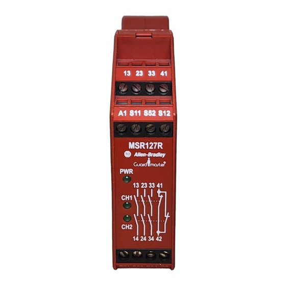
(a) Connections / Anschlüsse / Connexions
(b)
A1 & A2 = Power
S52 & S12 = Safety input (N/C)
S21 & S22 = Safety input (N/C)
S11 & S52 = Safety input (single channel) (N/C)
S12 & S34 = Monitoring feedback loop
Incorporating reset button
13 & 14
= Safety output 1 (N/O)
23 & 24
= Safety output 2 (N/O)
33 & 34
= Safety output 3 (N/O)
41 & 42
= Auxilary output (N/C)
S52
S12
13
23
33
Logic Ch1
Logic CH2
K2
K1
CH1
CH2
14
24
34
S22
13
23
33
A1
S11
S52
S12
(c) LED Indication
PWR (GREEN) - Illuminates when power on
CH1 (GREEN) - Illuminates when K1 is closed
CH2 (GREEN) - Illuminates when K2 is closed
S21
S22
S34
14
24
34
41
42
41
A2
42
Publicité

Manuels Connexes pour Allen-Bradley MINOTAUR MSR127R


Sommaire des Matières pour Allen-Bradley MINOTAUR MSR127R
- Page 1 MONITORING SAFETY RELAY MINOTAUR MSR127R-MSR127T ÜBERWACHUNGS-/SICHERHEITSRELAIS RELAIS DE SECURITE POUR CONTROLE Installation Instructions Einbauanleitung Notice D'installation RETAIN THESE INSTRUCTIONS DIESE ANLEITUNG AUFBEWAHREN CONSERVEZ CES INSTRUCTIONS Installation must be in accordance with the following steps and must be carried L’installation doit être effectuée conformément aux instructions suivantes, Die Installation muß...
- Page 2 Deutsch / Français (a) Wiring example 1 / Anschlußbeispiele 1 / Exemples de câblage 1 (b) Lichtschranke Ausgang 1 Ausgang 2 / Barrière photoélectrique Reset Light Curtain, 24VDC Out 1 Out 2 Out 1 Out 2 (c) Rückstellung / Initialisation (d) Lichtschranke, manuelle Rückstellung, überwachter Ausgang / Barrière photoélectrique, initialisation...
- Page 3 (a) Abnehmbare Klemmen - nur bei ‘P’- Position 1 Ausführungen / Bornes amovibles – (a) Removable Terminals disponibles sur versions P uniquement available on 'P' versions only (b) Um die Klemmen abzunehmen - Schraubenzieher in Position 1 ansetzen und langsam in Position 2 bringen/ Pour ôter les bornes : insérer un tournevis au repère 1 et baisser lentement jusqu'au repère 2...
- Page 4 REPARATION REPAIR REPARATUR Dans l'éventualité d'un problème technique ou d'une détérioration de cet If there is any malfunction or damage, no attempts should be made to repair it. Falls Fehlfunktionen oder Schäden auftreten, keine Versuche zur Reparatur appareil, il doit être remplacé immédiatement avant la remise en production de The unit should be replaced before machine operation is allowed.