Chapitres
Table des Matières

Sommaire des Matières pour Project 2000 12600 Série
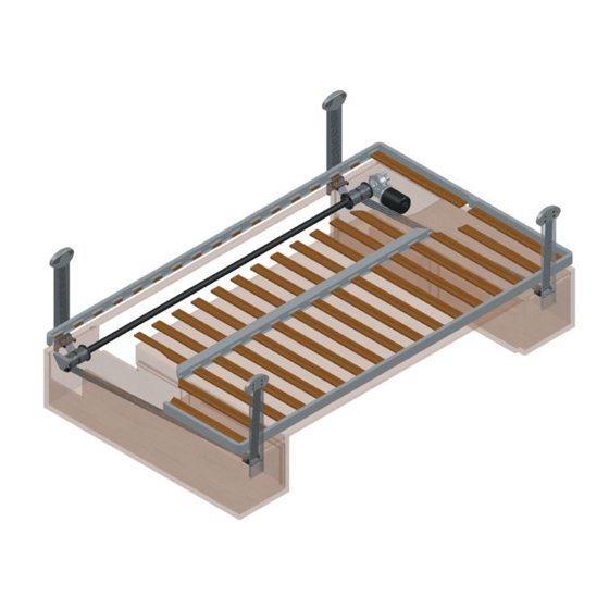
- Page 1 Manuale di uso e manutenzione Manual of use and maintenance Manuel d’utilisation et d’entretien Gebrauchs und Wartungshandbuch Serie Art. 12600 • ProBedLifting & E-LineBedLifting...
-
Page 2: Table Des Matières
INDICE 1.0 PREMESSA 1.1 IMPORTANZA DEL MANUALE, USO E CONSERVAZIONE DELLO STESSO. Questo manuale Vi aiuterà a conoscere e ad usare con il miglior rendimento il Vostro dispositivo sollevamento letto PROJECT 2000. Leggerlo attentamente prima di utilizzare la macchina. PREMESSA Il manuale è... -
Page 3: Informazioni Generali
2.1 DATI DI IDENTIFICAZIONE DEL COSTRUTTORE E DEI PRODOTTI. 5.1 INSTALLAZIONE MECCANICA: COSTRUTTORE: PROJECT 2000 S.r.l. Via Vivaldi 40/A – IT 50041 CALENZANO (FI) Procedere all’installazione del dispositivo sollevamento letto tenendo conto della portata massima. IL PIANO DEL LETTO TUTTO COMPRESO, DISPOSITIVO SOLLEVAMENTO LETTO, MATERASSO, CUSCINO, COPERTE E QUANT’ALTRO NON DEVE SUPERARE... -
Page 4: Installazione Elettrica
Posizionare le quattro piastre fissaggio cintura (TAV. A – Fig. A.2) in un punto idoneo che corrisponde al punto più alto che si vuol far raggiungere al dispositivo, tenendo conto dell’allineamento delle cinghie agli scorrevoli e della distanza minima che deve rimanere tra scorrevole e piastra fissaggio cintura (TAV. -
Page 5: Avviamento E Funzionamento
5.2.3 CABLAGGI Il letto si muove verticalmente all’interno di una struttura appositamente realizzata, ed il suo movimento è limitato da due estremi: - verso l’alto, il limite è rappresentato dal sensore di fine corsa; - verso il basso, il limite è rappresentato dal punto più basso programmato. Per questo motivo è... - Page 6 • è presente un comando al motore, c’è il ritorno del segnale contapassi, ma il sensore di fine corsa risulta premuto. 5.3 ENCODER MECCANICO CONNESSIONI DELLA SCHEDA La condizione di allarme viene resettata spegnendo e riaccendendo il controller. Se questo viene fatto senza aver risolto la causa, al primo movimento del letto si avrà...
- Page 7 3) Facendo scendere il letto premere il pulsante di fine corsa del punto più basso (quello montato sull’encoder meccanico) il letto si 5.3.2 CONNESSIONI DEL MOTORE deve arrestare immediatamente. Fatto questa verifica i fine corsa sono sincronizzati. SALITA DEL DISPOSITIVO Fine corsa salita (C-3) FIG.
-
Page 8: Messa In Servizio E Collaudo
Lo schema di Fig. 3.A riassume tutti i collegamenti da realizzare fra la scheda e gli altri elementi per ottenere un impianto correttamente 5.3.5 DISPOSITIVI DI SICUREZZA funzionante. Si ricorda che i collegamenti del motore (pin 3 e 7 del connettore 8 poli) e i collegamenti dell’alimentazione (pin 4 e 8 del connettore 8 5.3.5.1 PROTEZIONE CONTRO ACCESSI INDESIDERATI Il controller è... -
Page 9: Interventi Di Manutenzione
10.0 SMANTELLAMENTO E DEMOLIZIONE Il costruttore “Project 2000” garantisce 24 mesi i vari componenti del dispositivo sollevamento letto dalla data di acquisto del prodotto. I particolari difettosi non dovranno essere manomessi e dovranno essere accompagnati dal numero di matricola posto sulla targhetta La Ditta costruttrice ha progettato e realizzato i dispositivi sollevamento letto per una durata di almeno 500 ore di funzionamento inter- applicata sul dispositivo sollevamento letto. -
Page 10: Tavole
Il costruttore “Project 2000” può decidere di sostituire i particolari difettosi anziché di ripararli. Nel caso in cui la riparazione o la sostitu- zione risulti negativa, il cliente può... -
Page 11: Ed Identificabili Correttamente Nonostante L'usura
TABLE OF CONTENTS CONTROLLO ANNUALE ANNO _________ DATA ________________ N° CICLI__________ NON OK NOTE I segnali acustici e luminosi sono efficienti? Gli organi di comando per il sollevamento e l’abbassamento sono efficienti? Gli organi di comando per il sollevamento e l’abbassamento sono contrassegnati in maniera chiara e univoca ed identificabili correttamente nonostante l’usura? L’accoppiamento tra rullo/i porta cinghia e motoriduttore presenta giochi? Il motoriduttore è... -
Page 12: Introduction
• use when the vehicle is running MANUFACTURER: Project 2000 S.r.l. – Via Vivaldi, 40/A – IT 50041 Calenzano (FI) – VAT an tax No. 05025550483 The general warranty shall expire in case of: BED LIFTING SYSTEM SERIES 12600 •... -
Page 13: Mechanical Installation
MAXIMUM WEIGHT OF 400 KG. Fix the belt-fixing plates with suitable screws (we recommend 4.2x25 screws) in the four slots first, in 3.0 TECHNICAL INFORMATION order to adjust and correct any possible installation defect and then fix all of the remaining screws (TAB. A - Picture A.2) Place the bed frame inside of the vehicle on four temporary supports in order to keep it parallel to the vehicle floor. - Page 14 5.2.3 WIRING Logic ID Range Clamps Features - description Silk-screen printing MOT1 0 - 12Vdc CN1 - 8 Motor (BROWN) 12Vdc CN1 - 7 Positive power pole Timer 0 - 5Vdc CN1 - 6 Timer signal (GREEN) Limit switch 0 - 5Vdc CN1 - 5 End-of-stroke signal (ORANGE) MOT2...
-
Page 15: Security Devices
The bed moves vertically in a specific structure developed to this purpose and its stroke is limited by two ends: The causes can be the following: - on the upper side, the stroke is limited by an end-of-stroke sensor; • a command is sent to the motor but there is no feedback signal from the step counter;... - Page 16 5.3 MECHANICAL ENCODER 1) Control panel, by pressing the UP button the bed must go up and it must go down when pressing the DOWN button. CIRCUIT BOARD CONNECTION 2) When pressing the end-of-stroke button while lifting the bed to the highest position, the bed must immediately stop. 29/06/2011 3) Press the end-of-stroke button (the one mounted on the mechanical encoder) to set the lowest position while lowering the bed: the The circuit board is a controlling device equipped with: bed must immediately stop.
-
Page 17: Features - Description
5.3.2 MOTOR CONNECTIONS The diagram in picture 3.A summarizes all of the connections between the board and the other items that should be established in order for the system to work correctly. The motor connections (pin 3 and 7 of the 8-pole connector) and power connections (pins 4 and 8 of the 8-pole connector) must be carried out exactly as shown in the picture, paying attention to use cables with a minimum section of 4 mmq. -
Page 18: Start-Up And Testing
5.3.5 SECURITY DEVICES 8.0 IMPORTANT INFORMATION 5.3.5.1 PROTECTION AGAINST UNAUTHORIZED ACCESS The controller is equipped with a safety device to protect the system against unauthorized access, through activation in “ON” posi- • SAFETY DEVICES SHALL NOT BE TAMPERED WITH FOR ANY REASON. tion of the key switch located on the panel Picture 4.A;... -
Page 19: General Information On Safety Regulations
12.0 WARRANTY TERMS AND CONDITIONS The Manufacturer “Project 2000” guarantees the bed lifting system components for 24 months after purchase. Defective parts shall not be tampered with and they shall be returned together with the serial number indicated on the plate located on the bed lifting system. - Page 20 YEARLY CHECK YEAR _________ DATE ________________ No. of CYCLES__________ NOT OK NOTES Are warning sound signals and lights working? Are the control devices for lifting and lowering the system working? Are the control devices for lifting and lowering the system clearly marked so that they can be correctly identified despite wear? Are there any clearances in the belt roller/s and the gearmotor coupling? Is the gearmotor perfectly working in all of its mechanical functions?
- Page 21 TABLE DES MATIÈRES 1.0 INTRODUCTION 1.1 IMPORTANCE DU MANUEL, UTILISATION ET CONSERVATION. Ce manuel vous aidera à connaître et à utiliser au mieux votre dispositif de levage pour lit PROJECT 2000. Lire attentivement avant d’utiliser la machine. INTRODUCTION Le manuel est destiné à l’utilisateur et/ou agent d’entretien du dispositif de levage pour lit et fait pleinement partie de ce dispositif.
-
Page 22: Informations Générales
également pour les courroies qui vont dans la direction opposée (TAB. B - Fig. B.2) FABRICANT : PROJECT 2000 S.r.l. Via Vivaldi 40/A – IT 50041 CALENZANO (FI) Après avoir monté le dispositif de levage pour lit sous le plan du lit, enrouler les courroies sur les arbres en prêtant attention au sens de... -
Page 23: Branchements Du Moteur
rotation du moteur et en effectuant un pré-enroulement d’au moins deux tours (TAB. B - Fig. B .3) La carte est un contrôleur équipé avec: LES QUATRE COURROIES DOIVENT OBLIGATOIREMENT ÊTRE PRé-ENROULéES SUR AU MOINS DEUX TOURS AU POINT LE - alimentation 12Vdc, 25A max;... -
Page 24: Demarrage Et Fonctionnement
Les fils n° 5 et 4 sont le branchement pour le moteur, pour leur câblage se référer au schéma de la fig. 2. Le lit se déplace verticalement à l’intérieur d’une structure spécialement fabriquée, et son mouvement est limité par deux extrémités : Les fils n°... -
Page 25: Encoder Mécanique Branchement De La Carte
L’accès au fonctionnement normal est indiqué par l’allumage des deux led flèche sur le panneau. 5.3 ENCODER MéCANIQUE BRANCHEMENT DE LA CARTE La protection se remet en fonction lorsque l’on active la modalité faible consommation, ou au moment de l’extinction du contrôleur. 5.2.4.2.2 RETABLISSEMENT APRES ALARME La carte est un contrôleur équipé... - Page 26 Comment effectuer le contrôle de la correcte connexion de fin de course: 5.3.2 BRANCHEMENTS DU MOTEUR Panneau de commande : appuyer sur le bouton pour la remonte, le lit remonte et en appuyant sur le bouton « descente » le lit baisse. Pendant la remonte du lit, appuyer sur le fin de course pour le point le plus haut : le lit doit s’arrêter tout de suit Pendant la descente du lit, appuyer sur le fin de course pour le point le plus bas (monté...
-
Page 27: Dispositifs Mécaniques
Le schéma de la Fig. 3.A résume tous les branchements à effectuer entre la carte et les autres éléments pour obtenir une installation 5.3.5 DISPOSITIFS DE SECURITE 5.3.5.1 PROTECTION CONTRE DES ACCES NON DESIRES qui fonctionne correctement. L’ o n rappelle que les branchements du moteur (broches 3 et 7 du connecteur 8 pôles) et les branchements de l’alimentation (broches 4 et 8 Le contrôleur est équipé... -
Page 28: Interventions D'entretien
Pour des interventions plus complexes, il est nécessaire de faire appel à du personnel spécialisé. Le fabricant « Project 2000 » garantit les différents composants du dispositif de levage pour lit pendant 24 mois à partir de la date d’achat du produit. Les détails défectueux ne devront pas être altérés et devront être accompagnés du numéro de matricule indiqué... -
Page 29: Cahier De Controle Du Dispositif Pour Le Levage
: dans ce cas la réparation sera facturée. Le fabricant “Project 2000” peut décider de remplacer les détails défectueux au lieu de les réparer. Dans le cas où la réparation ou le rem- placement ne seraient pas satisfaisants, le client peut décider de demander une réduction du montant de la facture ou annuler l’achat. - Page 30 INHALTSVERZEICHNIS CONTROLE ANNUEL ANNEE _________ DATE ________________ N° CYCLES__________ PAS OK NOTE Est-ce que les signaux acoustiques et lumineux fonctionnent bien? Est-ce que les organes de commande pour lever et baisser le lit fonctionnent bien? Est-ce que les organes de commande pour lever et baisser le lit sont marqués de façon claire et univoque et on peut les bien identifier malgré...
-
Page 31: Vorwort
Gebrauch unter den in Punkt 4 beschriebenen Zuständen. 1.1 WICHTIGKEIT, ANWENDUNG UND AUFBEWARUNG DES HANDBUCHES ACHTUNG! Dieses Handbuch wird Ihnen helfen die Bett-Hubvorrichtung PROJECT 2000 kennenzulernen und zu benutzen, um diese vorteilhaft einzusetzen. BETT-HUBVORRICHTUNGEN können, so wie alle Geräte mit beweglichen Teilen, zur Gefahrenquelle werden, falls nicht auf angemessener Weise angewendet und/oder geschützt. -
Page 32: Mechanische Installation
Nachdem Sie die Hubvorrichtung unter das Bett montiert haben, wickeln Sie die Riemen auf die Wellen auf und achten Sie dabei 3.0 TECHNISCHE ANGABEN auf den Drehsinn des Motors. Den Riemen zum Anfang mindestens zwei Mal um die Welle wickeln (Vorwicklung) (Tafel B - Fig. B .3) AN DER TIEFSTEN STUFE DES BETTES MÜSSEN DIE VIER RIEMEN OBLIGATORISCH MINDESTENS ZWEI MAL UM DIE WELLE Technische Merkmale: Beziehen Sie sich auf das Identifikationsschild auf dem Produkt GEWICKELT WERDEN;... - Page 33 5.2.1 VERBINDUNGEN DER PLATINE 5.2.3 VERKABELUNG FIG. 1 – FASTON VERBINDER ANSICHT - SEITE DER KONTAKTE Siebdruck ID logisch Range Klemmen Merkmale – Beschreibung MOT1 0 - 12Vdc CN1 - 8 Motor (BRAUN) 12Vdc CN1 - 7 Pol positiv Einspeisung Schrittzähler 0 - 5Vdc CN1 - 6...
-
Page 34: Sicherheitsvorrichtungen
Das Bett bewegt sich im vertikalen Sinn auf einer dazu bestimmten Struktur und die Bewegung ist von den zwei Endstellungen ein- 5.2.4.2.2 WIEDERHERSTELLUNG NACH ALARM gegrenzt: Das Steuergerät kann aus zwei Gründen Alarm anzeigen (man erkennt den Alarmzustand an der rot blinkenden LED und da es nicht •... - Page 35 Siebdruck ID logisch Range Klemmen Merkmale – Beschreibung AUFSTIEG DER VORRICHTUNG CN1 - 8 Einspeisung Pol negativ MOT2 0 - 12Vdc CN1 - 7 Motor (GRAU) Endschalter (B) Aufstieg Unbenutzt CN1 - 6 Unbenutzt F.C. (C-5) CN1 - 5 Endschalter (C-5) (ORANGE) (C-1) 12Vdc CN1 - 4...
- Page 36 5.3.2 VERBINDUNG DES MOTORS Das Schema in Fig. 3.A fasst alle Verbindungen zusammen, die zwischen der Platine und den anderen Elementen aufzustellen sind, um somit eine korrekt funktionierende Anlage zu haben. Man erinnert daran, dass die Verbindungen des Motors (PIN 3 und 7 des 8-poligen Steckers) und die Verbindungen der Einspeisung (PIN 4 und 8 des 8-poligen Steckers) genau laut Figur durchzuführen sind, dabei darauf achten, dass die Kabel einen Querschnitt von mindestens 4 mm_ haben.
-
Page 37: Inbetriebnahme Und Abnahme
5.3.5 SICHERHEITSVORRICHTUNGEN 8.0 GRUNDLEGENDE HINWEISE 5.3.5.1 SCHUTZ VOR UNERWÜNSCHTEN ZUGÄNGEN Das Steuergerät hat einen Schutz, um nicht erwünschte Zugänge zu vermeiden „Schlüssel auf dem Bedienungspaneel“ Fig. 4.A, bei • DIE VERSCHIEDENEN SICHERHEITSVORRICHTUNGEN DÜRFEN AUF KEINEN FALL UNERLAUBT VERÄNDERT WERDEN. Schlüsselstellung in Position OFF ist das System blockiert. Zur Entriegelung der Schutzvorrichtung um an die normalen Funktionen zu •... -
Page 38: Allgemeine Hinweise Zu Den Sicherheitsnormen
Anlage verbunden wurde. In diesem Fall berechnet man Reparaturkosten. Der Hersteller „Project 2000“ kann sich entweder für den Ersatz der defekten Teile entscheiden oder diese reparieren. Im Fall einer negativ ausgehenden Reparatur oder Ersetzung kann der Kunde sich für eine Verminderung der Berechnung oder die Stornierung... - Page 39 JAHRESKONTROLLE JAHRE _________ DATUM ________________ N° ZYKLEN__________ NICHT OK NOTEN Sind die akustischen und visuellen Signale funktionstüchtig? Sind die Komponenten zum Heben und Senken funktionstüchtig? Sind die Komponenten zum Heben und Senken trotz Abnutzung klar und eindeutig gekennzeichnet und korrekt identifizierbar? Weist die Verbindung zwischen Gurthalterolle/n und Motoruntersetzungsgetriebe Spiel auf? Ist das Motoruntersetzungsgetriebe in allen mechanischen Funktionen funktionstüchtig? Ist das Brems- und Arretiersystem funktionstüchtig?
- Page 40 NOTE • NOTES • NOTE • NOTEN...
- Page 41 Via Vivaldi, 40/a • IT-50041 Calenzano (FI) Tel. +39 055 8825239 Fax +39 055 8878086 web: www.project-2000.it • E-mail: info@project-2000.it...