probst RG-20/80 Instructions D'emploi
Masquer les pouces
Voir aussi pour RG-20/80:
- Instructions d'emploi (49 pages) ,
- Instructions d'emploi (121 pages)
Publicité
Les langues disponibles
Les langues disponibles
Liens rapides
Publicité

Manuels Connexes pour probst RG-20/80


Sommaire des Matières pour probst RG-20/80
- Page 1 RG-20/80 Betriebsanleitung Operating Instructions Instructions d'emploi 54500002...
- Page 5 RG-20/80 Betriebsanleitung 54500002 Original Betriebsanleitung...
- Page 6 Störungsbeseitigung ........................19 Reparaturen ........................... 19 Prüfungspflicht ..........................20 Hinweis zum Typenschild ....................... 21 Hinweis zur Vermietung/Verleihung von PROBST-Geräten ............21 Entsorgung / Recycling von Geräten und Maschinen ..............21 Änderungen gegenüber den Angaben und Abbildungen in der Betriebsanleitung sind vorbehalten. 54500002...
- Page 7 DIN EN ISO 13857 Sicherheit von Maschinen - Sicherheitsabstände gegen das Erreichen von Gefährdungsbereichen mit den oberen und unteren Gliedmaßen Dokumentationsbevollmächtigter: Name: Jean Holderied Anschrift: Probst GmbH; Gottlieb-Daimler-Straße 6; 71729 Erdmannhausen, Germany Unterschrift, Angaben zum Unterzeichner: Erdmannhausen, 09.08.2024..............(Eric Wilhelm, Geschäftsführer) 54500002...
- Page 8 Sicherheit Sicherheit Sicherheitshinweise Lebensgefahr! Bezeichnet eine Gefahr. Wenn sie nicht gemieden wird, sind Tod und schwerste Verletzungen die Folge. Gefährliche Situation! Bezeichnet eine gefährliche Situation. Wenn sie nicht gemieden wird, können Verletzungen oder Sachschäden die Folge sein. Verbot! Bezeichnet ein Verbot. Wenn es nicht eingehalten wird, sind Tod und schwerste Verletzungen, oder Sachschäden die Folge.
- Page 9 Sicherheit Sicherheitskennzeichnung VERBOTSZEICHEN Symbol Bedeutung Bestell-Nr. Größe 29040210 Ø 30 mm Niemals unter schwebende Last treten. Lebensgefahr! 29040209 Ø 50 mm 29040204 Ø 80 mm 29040216 Ø 30 mm Greifgüter niemals außermittig aufnehmen, stets im 29040215 Ø 50 mm Lastschwerpunkt. 29040214 Ø...
- Page 10 Sicherheit Persönliche Sicherheitsmaßnahmen Jeder Bediener muss die Bedienungsanleitung für das Gerät mit den Sicherheitsvorschriften • gelesen und verstanden haben. Das Gerät und alle übergeordneten Geräte in/an die das Gerät eingebaut ist, dürfen nur von dafür • beauftragten und qualifizierten Personen betrieben werden. •...
- Page 11 Sicherheit Sicherheit im Betrieb 2.9.1 Allgemeines • Die Arbeit mit dem Gerät darf nur in bodennahem Bereich erfolgen. Das Schwenken des Gerätes über Personen hinweg ist untersagt. Der Aufenthalt unter schwebender Last ist verboten. Lebensgefahr! • Das manuelle Führen ist nur bei Geräten mit Handgriffen erlaubt. •...
- Page 12 Allgemeines Bestimmungsgemäßer Einsatz Das Gerät RG-20/80 dient ausschließlich zum Greifen, Transportieren und Verlegen von Betonrohren mit einem Außendurchmesser von 200 mm bis 800 mm. Das Gerät ist mit einer Einhängeöse für diverse Anschlagmittel ausgerüstet und kann somit an ein Trägergerät (z.B.
- Page 13 Allgemeines NICHT ERLAUBTE TÄTIGKEITEN: Eigenmächtige Umbauten am Gerät oder der Einsatz von eventuell selbstgebauten Zusatzvorrichtungen gefährden Leib und Leben und sind deshalb grundsätzlich verboten!! Tragfähigkeiten (WLL) des Gerätes dürfen nicht überschritten und Nennweiten/Greifbereiche dürfen nicht überschritten bzw. unterschritten werden. Alle nicht bestimmungsgemäßen Transporte mit dem Gerät sind strengstens untersagt: das Transportieren von Menschen und Tieren.
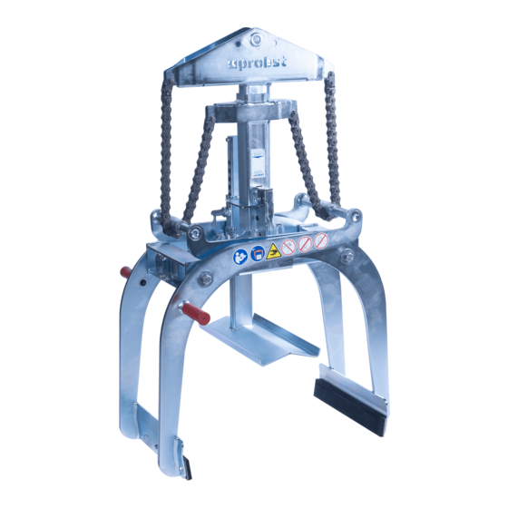
- Page 14 Allgemeines Übersicht und Aufbau Einhängebolzen für Kranhaken Wechselautomatik Federriegel Handgriff Höhenverstellbare Auflage Greifbacken Technische Daten Die genauen technischen Daten (wie z.B. Tragfähigkeit, Eigengewicht, etc.) sind dem Typenschild zu entnehmen. 54500002 10 / 21...
- Page 15 Installation Installation Mechanischer Anbau Nur Original-Probst-Zubehör verwenden, im Zweifelsfall Rücksprache mit dem Hersteller halten. Die Tragfähigkeit des Trägergerätes/Hebezeuges darf durch die Last des Gerätes, der optionalen Anbaugeräte (Drehmotor, Einstecktasche, Kranausleger etc.) und die zusätzliche Last der Greifgüter nicht überschritten werden! Greifgeräte müssen immer kardanisch aufgehängt werden, so dass sie in jeder Position frei...
- Page 16 Installation 4.1.4 Einstecktaschen (optional) Um eine sichere Verbindung zwischen dem Gabelstapler und der Einstecktasche (3) herzustellen, fährt man mit den Gabelstapler-Zinken (1) in die Einstecktasche (3) hinein. Danach arretiert man diese entweder mittels Arretierungsschrauben (2), welche durch eine vorzusehende Bohrung in die Stapler-Zinken (1) gesteckt wird, oder mittels einer Kette oder eines Seils (4), das durch die Ösen an den Einstecktasche (3) und um den Gabelträger () gelegt werden muss.
- Page 17 Einstellungen Einstellungen Einstellung des Greifbereichs Durch Änderung des Greifbereichs können mit dem Gerät unterschiedlich große Greifgüter (Betonrohre) gegriffen werden. Bevor ein Greifgut angehoben und versetzt werden kann, muss der entsprechende Greifbereich und die höhenverstellbare Auflage eingestellt werden. • Die Einstellung des Greifbereichs darf niemals auf beiden Seiten gleichzeitig erfolgen. Den Greifbereich immer zuerst auf der einen u.
- Page 18 Einstellungen 5.1.1 Einstellung der höhenverstellbaren Auflage Die Einstellung der höhenverstellbaren Auflage erfolgt folgendermaßen: • Federstecker nach oben ziehen und um 180° verdrehen. • Rechteckrohr verschieben, bis die richtige Eintauchtiefe eingestellt ist. Federstecker wieder nach oben ziehen und um 180° verdrehen. Rechteckrohr so lange hin- und herschieben, bis der Federstecker in das entsprechende Loch einrastet.
- Page 19 Bedienung Bedienung Bedienung allgemein Gerät mit der Einhängeöse am Trägergerät/Hebezeug befestigen. • Öffnungsweite und höhenverstellbare Auflage entsprechend dem zu hebenden Greifgut • (Betonrohr) einstellen. Gerät über dem Greifgut positionieren und absenken, bis Auflage passend aufliegt. • Sobald das Gerät komplett abgesetzt ist, entriegelt die Wechselautomatik und schließt beim •...
- Page 20 Bedienung Rohre müssen immer im Schwerpunkt gegriffen werden, da ansonsten Abgleitgefahr besteht! Die zu greifenden Betonrohre müssen vollständig ausgehärtet sein! Greifgüter können wegrutschen oder wegrollen, wenn sie im Gefälle, auf unbefestigtem oder unebenem Untergrund abgelegt werden! Tod und schwere Verletzungen können die Folge sein. Greifgüter immer nur auf waagrechtem, festem und ebenem Untergrund ablegen! Rohre prinzipiell gegen Wegrollen sichern, zum Beispiel mit Keilen.
- Page 21 Bedienung Darstellung der Wechselautomatik Das Gerät ist mit einer Wechselautomatik ausgerüstet, das heißt das ÖFFNEN und SCHLIESSEN der Greifarme erfolgt durch das Absetzen und Anheben des Gerätes. Bildliche Darstellungen der Schaltpositionen der Wechselautomatik: • Gerät ist durch das Trägergerät • Gerät wird auf das Greifgut •...
- Page 22 Wartung und Pflege Wartung und Pflege Wartung Um eine einwandfreie Funktion, Betriebssicherheit und Lebensdauer des Gerätes zu gewährleisten, sind die in der unteren Tabelle aufgeführten Wartungsarbeiten nach Ablauf der angegebenen Fristen durchzuführen. Es dürfen nur Original-Ersatzteile verwendet werden, ansonsten erlischt die Gewährleistung. Alle Arbeiten dürfen nur bei stillgelegtem Gerät erfolgen! Bei allen Arbeiten muss sichergestellt sein, dass sich das Gerät nicht unabsichtlich schließen kann.
- Page 23 Wartung und Pflege Störungsbeseitigung STÖRUNG URSACHE BEHEBUNG Die Klemmkraft ist nicht ausreichend, die Last rutscht (optional) Die Greifbacken sind abgenutzt Greifbacken erneuern (optional) Traglast ist größer als zulässig Traglast reduzieren Greifbereichs-Einstellung Es ist der falsche Greifbereich Greifbereich entsprechend auf die zu (optional) eingestellt transportierenden Greifgüter einstellen...
- Page 24 Die dementsprechenden gesetzlichen Bestimmungen u. die der Konformitätserklärung sind zu • beachten! • Die Durchführung der Sachkundigenprüfung kann auch durch den Hersteller Probst GmbH erfolgen. Kontaktieren Sie uns unter: service@probst-handling.de • Wir empfehlen, nach durchgeführter Prüfung und Mängelbeseitigung des Gerätes die Prüfplakette „Sachkundigenprüfung/ Expert inspection“...
- Page 25 (z.B. Kran, Kettenzug, Gabelstapler, Bagger...) mit zu berücksichtigen. Beispiel: Hinweis zur Vermietung/Verleihung von PROBST-Geräten Bei jeder Verleihung/Vermietung von PROBST-Geräten muss unbedingt die dazu gehörige Original- Betriebsanleitung mitgeliefert werden (bei Abweichung der Sprache des jeweiligen Benutzerlandes, ist zusätzlich die jeweilige Übersetzung der Original-Betriebsanleitung mit zuliefern)! Entsorgung / Recycling von Geräten und Maschinen...
- Page 26 (durch eine autorisierte Fachwerkstatt)! Nach jeder erfolgten Durchführung eines Wartungsintervalls muss unverzüglich dieser Wartungsnachweis (mit Unterschrift u. Stempel) an uns übermittelt werden. per E-Mail an: service@probst-handling.de / per Fax oder Post Betreiber: _ _ _ _ _ _ _ _ _ _ _ _ _ Gerätetyp:...
- Page 29 RG-20/80 Operating Instructions 54500002 Translation of original operating instructions...
- Page 30 Safety procedures .......................... 20 Hints to the type plate ........................21 Hints to the renting/leasing of PROBST devices ................21 Disposal / recycling of devices and machines .................. 21 We hereby reserve the right to make changes to the information and illustrations in the operating instructions.
- Page 31 Safety of machinery - safety distances to prevent hazard zones being reached by upper and lower limbs. Authorized person for EC documentation: Name: Jean Holderied Address: Probst GmbH; Gottlieb-Daimler-Straße 6; 71729 Erdmannhausen, Germany Erdmannhausen, 09.08.2024................(Eric Wilhelm, Managing Director) 54500002...
- Page 32 DIN EN 13155; UK regulation BS EN 13155; AS regulation AS 4991:2004. Authorized person for UK documentation: Name: Nigel Hughes Address: Probst Ltd ; Unit 2 Fletcher House; Stafford Park 17; Telford Shropshire TF3 3DG, United Kingdom Signature, information to the subscriber: Authorized person for AS documentation: Name: Will Freeman Address: Probst Australia Pty Ltd;...
- Page 33 Safety Safety Safety symbols Danger to life! Identifies imminent hazard. If you do not avoid the hazard, death or severe injury will result. Hazardous situation! Identifies a potentially hazardous situation. If you do not avoid the situation, injury or damage to property can result.
- Page 34 Safety Safety Marking PROHIBITION SIGN Symbol Meaning Order-No. Size 29040210 Ø 30 mm It is not allowed to stand under hanging loads. Danger to life! 29040209 Ø 50 mm 29040204 Ø 80 mm 29040216 Ø 30 mm Do not lift any components off-centre (always in centre of gravity). 29040215 Ø...
- Page 35 Safety Personal safety requirements Each operator must have read and understood the operating instructions (and all safety instructions). Only qualified, authorized personal is allowed to operate the device and all devices which are connected (lifting device/carrier). The manual guiding is only allowed for devices with handles. Otherwise there is a risk of injury to the hands! Protective equipment Protective clothing...
- Page 36 Safety Safety in operation 2.9.1 General • The use of the device is only permitted in proximity to the ground. Do not swing it over people heads. The stay under lifted load is forbidden. Danger to Life! • The manual guiding of the device is only allowed at the handles. •...
- Page 37 General Authorized use The device (RG-20/80) is exclusively used for gripping, transporting and laying concrete pipes with an outside diameter of 200 mm to 800 mm. The device is equipped with a lifting eye for various lifting tackle and can therefore be attached to a carrier (e.g.
- Page 38 General Survey and construction Survey and construction Suspension lug for crane hook Automatic release Spring bolt Handle Height adustable Rubbergripper support Technical data The exact technical data (carrying capacity / working load limit (WLL), dead weight, etc.) are listed on the type plate. 54500002 10 / 21...
- Page 39 Installation Installation Mechanical connection Use only original accessories, in case of doubt consult the manufacturer. Take care that the carrying capacity / working load limit (WLL) of the lifting device/carrier is not exceeded, through the load of the device, the optional attaching devices (turning device, fork sleeves, crane boom etc.) and the additional load of the gripping goods! Gripping devices always have to be gimballed, so they can swing freely in any position.
- Page 40 Installation 4.1.4 Fork sleeves (optional) In order to connect the forklift truck and the fork sleeves (3), the forklift truck forks (1) are inserted into the fork sleeves (3). The forks (1) are locked either by using the locking screws (2), which are inserted through a hole in the forks (1), or by using a chain or rope, which must be placed through the eyelet on the fork sleeves (3) and around the fork carrier ().
- Page 41 Adjustment of the gripping range 5.1.1 Adjustment of the gripping range By adjusting the gripping range, the device (RG-20/80) is suitable for different sizes of gripping goods (concrete tubes). Before the product can be lifted and transported, the gripping range has to be adjusted to the dimensions of the product.
- Page 42 Adjustments 5.1.2 Adjustment of the height adjusting support The height-adjustable support is adjusted as follows: • Pull the spring cotter pin upwards and turn it 180°. • Move the rectangular tube until the correct inside height has been adjusted. Pull the spring cotter pin upwards again and turn it by 180°.
- Page 43 Operation Operation Device operation Connect the device with the suspension bolt to the lifting equipment/carrier (e.g. with crane hook). • • Adjust the gripping range and the height support. • Lower the device on the gripping good (concrete tube) until the automatic release unlocks, when the device is lifted.
- Page 44 Operation The concrete pipes must be gripped in centre of gravity, otherwise there is a danger of slipping off! Be sure that the concrete tubes are completely hardened. Gripping goods can slip away or roll away if they are deposited on slopes, unpaved or uneven ground! Death and serious injuries can result.
- Page 45 Operation Picture of the automatic release The device is equipped with an automatic release, that means the OPENING and CLOSING of the gripping arms results through the set down and lifting of the device. Pictures of the positions of the automatic release: •...
- Page 46 Maintenance and care Maintenance and care Maintenance To ensure the correct function, safety and service life of the device the following points must be executed in the maintenance interval. Used only original spare parts, otherwise the warranty expires. All operations may only be made in closed state of the device! For all operations you have to make sure, that the device will not close unintended.
- Page 47 Maintenance and care Trouble shooting ERROR CAUSE REPAIR The clamping-power is not big enough, the load is slipping out (optional) The grippers are worn Replace the grippers (optional) The maximum load is exceed Reduce the weight of. the load (Adjustment of the gripping range) The actual opening width is not Adjust the gripping range according (optional)
- Page 48 1 year and all recognized errors are removed (→ DGUV norm 100-500). The corresponding legal regulations and the regulations of the declaration of conformity must be • observed! The expert inspection can also be done by the manufacturer Probst GmbH. • Contact us at: service@probst-handling.de •...
- Page 49 Example: Hints to the renting/leasing of PROBST devices With every renting/leasing of PROBST devices the original operating instructions must be included unconditionally (in deviation of the user´s country's language, the respective translations of the original operating instructions must be delivered additionally)!
- Page 50 After each completed performance of a maintenance interval the included form must be fill out, stamped, signed and send back to us immediately. via e-mail to service@probst-handling.de / via fax or post Operator: _ _ _ _ _ _ _ _ _ _ _ _ _...
- Page 53 RG-20/80 Instructions d'emploi 54500002 Traduction des instructions d'emploi originales...
- Page 54 Devoir de contrôle .......................... 20 Informations concernant la plaque signalétique ................20 Remarque concernant la location/le prêt des engins PROBST ............. 21 Elimination / recyclage des appareils et des machines ..............21 Nous nous réservons le droit de modifier les informations et les illustrations du mode d'emploi.
- Page 55 Sécurité des machines ― Distances de sécurité empêchant les membres supérieurs et inférieurs d'atteindre les zones dangereuses. Personne autorise pour EC-documentation: Nom: Jean Holderied Adresse: Probst GmbH; Gottlieb-Daimler-Straße 6; 71729 Erdmannhausen, Germany Signature, informations ou signataire : Erdmannhausen, 12.08.2024................(Eric Wilhelm, Directeur général)
- Page 56 Sécurité Sécurité Instructions de sécurité Danger mortel ! Indique un danger. Si elle n'est pas évitée, elle peut entraîner la mort et des blessures graves. Situation dangereuse ! Indique une situation dangereuse. Le fait de ne pas l'éviter peut entraîner des blessures ou des dommages matériels.
- Page 57 Sécurité Signalisation de sécurité PANNEAUX D’INTERDICTION Symbole Signification Réf. Taille 29040210 Ø30 mm Ne jamais se placer sous une charge suspendue. 29040209 Ø50 mm Danger de mort ! 29040204 Ø80 mm 29040216 Ø30 mm Ne jamais saisir d’objet de manière excentrée (toujours les saisir 29040215 Ø50 mm en leur milieu).
- Page 58 Sécurité Mesures de sécurité personnelle • Chaque opérateur doit avoir lu et assimilé la notice d’instructions de l’appareil, ainsi que les règles de sécurité. • L'appareil et tous les appareils sur et dans lesquels l'appareil est monté ne peuvent être utilisés que par des personnes dûment mandatées, qualifiées et habilitées.
- Page 59 Sécurité Sécurité en cours de fonctionnement 2.9.1 Généralités • Ne travailler avec l’engin qu’à proximité du sol. Il est interdit de faire passer l’engin au-dessus des personnes. • En règle générale, il est interdit de stationner sous une charge suspendue. Danger de mort ! •...
- Page 60 Généralités Utilisation conforme L'appareil RG-20/80 est exclusivement utilisé pour la préhension, le transport et la pose de tuyaux en béton d'un diamètre extérieur de 200 mm à 800 mm. L'appareil est équipé d'un œillet de suspension pour différentes élingues et peut donc être fixé sur un support (par ex.
- Page 61 Généralités NON AUTORISÉ ACTIVITES: Toute modification effectuée sur l’appareil de la propre autorité de l’utilisateur ainsi que l‘emploi par ce dernier de dispositifs auxiliaires éventuellement réalisés par lui-même, représentent un risque de danger corporel ou mortel et sont, en conséquence, fondamentalement interdits!! Les charges admissibles (WLL) de l'appareil ne doivent pas être dépassées et les diamètres nominaux/zones de préhension ne doivent pas être dépassés ou ne pas être atteints.
- Page 62 Généralités Vue d´ensemble et structure Œillet de transport Inverseur automatique Barre à ressort Poignée Support en hauteur Mâchoire Caractéristiques techniques Les caractéristiques techniques détaillées (par ex. charge maximale, poids propre, etc.) figurent dans la plaque signalétique. 54500002 10 / 21...
- Page 63 Installation Montage sur l’appareil porteur N’utiliser que des accessoires Probst d’origine, en cas de doute prendre contact avec le fabricant. La charge admissible de l’appareil porteur /engin de levage ne doit pas être dépassée par la charge de l’appareil et des appareils rapportés (moteur vireur, poches à emboîter, potence etc.) ainsi que par la charge supplémentaire des objets à...
- Page 64 Installation 4.1.4 Fourreaux (en option) Pour établir une liaison sûre entre le chariot élévateur et la poche d'insertion (3), on introduit les dents du chariot élévateur (1) dans la poche d'insertion (3). Ensuite, on les bloque soit au moyen de vis de blocage (2), qui sont introduites dans un trou à prévoir dans les dents du chariot élévateur (1), soit au moyen d'une chaîne ou d'une corde (4), qui doit être passée dans les œillets de la poche de rangement (3) et autour du tablier porte-fourche ().
- Page 65 Réglage Réglage Réglage de l’ouverture En changeant la plage de préhension, l'appareil peut être utilisé pour saisir des marchandises de différentes tailles (tuyaux en béton). Avant qu'un matériau à saisir puisse être soulevé et déplacé, il faut régler la plage de préhension correspondante et le support réglable en hauteur.
- Page 66 Réglage 5.1.1 Réglage du support Le support réglable en hauteur se règle comme suit : • Tirez la barre à ressort vers le haut et tournez-la de 180°. • Déplacer le tube rectangulaire jusqu'à ce que la profondeur d'immersion correcte soit réglée. Tirez à...
- Page 67 Maniement Maniement Maniement généralités • Fixer la pince pour tuyaux RG 20-80 avec l’œillet d’accrochage au moyen de levage. • Régler l’ouverture des mâchoires et le support en fonction du tuyau à transporter. • Descendre la pince sur le tuyau jusqu’à ce que le support s’y adapte et que l’inverseur automatique se verrouille. •...
- Page 68 Maniement Les tuyaux doivent toujours être saisis au centre de gravité, sinon ils risquent de glisser ! Les tuyaux en béton à saisir doivent être complètement durcis! Les grappins peuvent glisser ou rouler s'ils sont déposés sur une pente, sur un sol non pavé ou irrégulier ! Cela peut entraîner la mort et des blessures graves.
- Page 69 Maniement Images du système de changement automatique L'appareil est équipé d'un système de commutation entièrement automatique, c'est-à-dire que l'OUVERTURE et la FERMETURE des bras de préhension s'opèrent par le dépôt et le soulèvement de l'appareil. Représentations schématiques des positions de commutation du système automatique de changement. •...
- Page 70 Maintenance et entretien Maintenance et entretien Maintenance Pour que l´appareil fonctionne parfaitement, pour assurer sa sécurité de fonctionnement et une longue durée de vie, il est impératif d’effectuer les opérations de maintenance spécifiées dans le tableau ci- dessous aux intervalles prescrits. Utiliser exclusivement des pièces de rechange d’origine ;...
- Page 71 Maintenance et entretien Élimination des dérangements DÉRANGEMENT CAUSE DÉPANNAGE La force de serrage est insuffisante, la charge glisse. (optional) • • Les mâchoires sont usées. Remplacer les mâchoires. (optional) • • La charge est supérieure à celle Réduire la charge autorisée.
- Page 72 Observer les prescriptions correspondantes des associations professionnelles déclaration de conformité. • Le contrôle expert peut également être effectué par le fabricant Probst GmbH. Contactez-nous à : service@probst-handling.de • Lorsqu’un contrôle a été effectué et que les déficiences ont été réparées sur l´appareil, nous conseillons d’apposer la plaquette „CONTRÔLE DE SÉCURITÉ“...
- Page 73 Elimination / recyclage des appareils et des machines Remarque concernant la location/le prêt des engins PROBST Lors de chaque location/prêt d’un engin PROBST, les instructions d’emploi originales correspondantes doivent impérativement être jointes (si la langue n’est pas celle de l’utilisateur, une traduction des instructions d’emploi originales dans la langue adéquate doit être fournie) !
- Page 74 (signée et revêtue de votre cachet). par email à: service@probst-handling.de / par fax ou par courier. Opéateur: _ _ _ _ _ _ _ _ _ _ _ _ _ Modèle:...
- Page 75 43100386 21000226 21000226 20100017 43100345 21000171 21000134 20000037 43100346 siehe separate Liste see separate list 20440008 20100018 33100004 20100017 43100592 20250038 20530019 33100004 20100015 20440008 31600008 21700011 20000037 20000035 30360002 20000006 20400005 40110040 20530038 20100018 20000037 20440008 33100004 44500009 21600016 20100018 20540033 33100004...
- Page 76 20100015 31600008 21700011 30360002 © all rights reserved conform to ISO 16016 Datum Name Benennung Unterteil Erst. 7.9.2006 Dietrich.Pannier Gepr. 8.12.2014 J.Werner FTZ-uni/multi 15/RG 20-80 Artikelnummer/Zeichnungsnummer Blatt E43100346 Zust. Urspr. G083-20002 Ers. f. Ers. d.
- Page 77 A54500002 RG-20/80 29040056 29040638 Auf beiden Seiten / on both sides Erstellt/Created: Zuletzt geändert/Last changed: Blatt / Sheet: 1 / 1 26.10.2010 / Baumann, D. 05.07.2023 / Simon, Swen Version: Einige der Abbildungen sind möglicherweise optionales Zubehör des Gerätes/Some of pictures may be optional equipment of the device.
- Page 78 Bitte beachten Sie, dass das Produkt ohne vorliegende Betriebsanleitung in Landessprache nicht eingesetzt / in Betrieb gesetzt werden darf. Sollten Sie mit der Lieferung des Produkts keine Betriebsanleitung in Ihrer Landessprache erhalten haben, kontaktieren Sie uns bitte. In Länder der EU / EFTA senden wir Ihnen diese kostenlos nach.