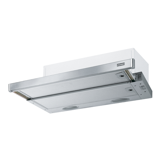
RECOMMENDATIONS AND SUGGESTIONS The Instructions for Use apply to several versions of this appliance. Accordingly, you may find descriptions of individual features that do not apply to your specific appliance. INSTALLATION • The manufacturer will not be held liable for any damages resulting from incorrect or improper installation.
CHARACTERISTICS Dimensions Min. Min. 500mm 650mm Components Ref. Q.ty Product Components Hood Body, complete with: Controls, Light, Blower, Filters Directional Air Outlet grille Reducer Flange ø 150-120 mm Closing element Ref. Q.ty Installation Components Screws 4,2 x 44,4 Screws 4,2 x 12,7 Screws 2,9 x 9,5 Q.ty Documentation Instruction Manual...
Page 5
INSTALLATION Drilling the Support surface and Fitting the Hood SCREW FITTING • The hood support surface must be 135 mm above the bottom surface of the wall units. • Drill the support with a ø 4,5 mm drill bit, using the drilling template provided.
Connections DUCTED VERSION AIR EXHAUST SYSTEM When installing the ducted version, connect the hood to the chimney using either a flexible or rigid pipe ø 150 or 120 mm, the choice of which is left to the installer. • To install a ø 120 mm air exhaust connection, insert the reducer flange 9 on the hood body outlet.
Page 7
Control panel M - V Light Switches the lighting system Light Switches the lighting system on and off. on and off. Motor Switches the extractor motor Motor Switches the extractor motor on and off. on and off. Speed Sets the operating speed of Speed Sets the operating speed of the extractor:...
Page 8
MAINTENANCE Grease filters CLEANING METAL CASSETTE GREASE FILTERS • The filters must be cleaned every 2 months, or more frequently in case of particularly heavy use of the hood. Filters can be washed in a dishwasher. • Pull out the sliding suction panel. •...
CONSIGLI E SUGGERIMENTI Questo libretto di istruzioni per l' u so è previsto per più versioni dell' apparecchio. É possibile che siano descritti singoli particolari della dotazione, che non riguardano il Vostro apparecchio. INSTALLAZIONE • Il produttore declina qualsiasi responsabilità per danni dovuti ad installazione non corretta o non conforme alle regole dell’arte.
Page 10
CARATTERISTICHE Ingombro Min. Min. 500mm 650mm Componenti Rif. Q.tà Componenti di Prodotto Corpo Cappa completo di: Comandi, Luce, Gruppo Ventilatore, Filtri Griglia direzionata Uscita Aria Flangia di riduzione D.150-120 Profilo chiusura Rif. Q.tà Componenti di Installazione Viti 4,2 x 44,4 Viti 4,2 x 12,7 Viti 2,9 x 9,5 Q.tà...
Page 11
INSTALLAZIONE Foratura Piano di supporto e Montaggio Cappa MONTAGGIO CON VITI • Il Piano di supporto della Cappa deve essere rientrante di 135 mm dal Piano inferiore dei Pensili. • Forare ø 4,5 mm il supporto utilizzando la Dima di foratura in dotazione.
Page 12
Connessioni USCITA ARIA VERSIONE ASPIRANTE Per installazione in Versione Aspirante collegare la Cappa alla tubazione di uscita per mezzo di un tubo rigido o flessibile di ø150 o 120 mm, la cui scelta è la- sciata all'installatore. • Per collegamento con tubo ø120 mm, inserire la Flangia di riduzione 9 sull’Uscita del Corpo Cappa.
Page 13
Quadro comandi M - V Luci Accende e spegne l’Impianto Luci Accende e spegne l’Impianto di Illuminazione. di Illuminazione. Motore Accende e spegne il motore Motore Accende e spegne il motore Aspirazione. Aspirazione. Velocità Determina la velocità di e- Velocità Determina la velocità di e- sercizio: sercizio: 1.
Page 14
MANUTENZIONE Filtri antigrasso PULIZIA FILTRI ANTIGRASSO METALLICI AUTOPORTANTI • Sono lavabili anche in lavastoviglie, e necessitano di essere lavati ogni 2 mesi circa di utilizzo o più frequentemente, per un uso particolarmente intenso. • Estrarre il carrello aspirante. • Togliere i Filtri uno alla volta, agendo sugli appositi agganci. •...
CONSEILS ET SUGGESTIONS La présente notice d' e mploi vaut pour plusieurs versions de l' a ppareil. Elle peut contenir des descriptions d' a c- cessoires ne figurant pas dans votre appareil. INSTALLATION • Le fabricant décline toute responsabilité en cas de dommage dû à une installation non correcte ou non conforme aux règles de l’art.
CARACTERISTIQUES Encombrement Min. Min. 500mm 650mm Composants Réf. Q.té Composants de Produit Corps Hotte équipé de:Commandes, Lumière, Groupe Ventilateur, Filtres Grille orientée Sortie de l ’Air Flasque de Réduction ø 150-120 mm Profil fermeture Réf. Q.té Composants pour l ’installation Vis 4,2 x 44,4 Vis 4,2 x 12,7 Vis 2,9 x 9,5...
INSTALLATION Perçage du Plan de support et Montage de la Hotte MONTAGE AU MOYEN DE VIS • Le Plan de support de la Hotte doit être monté plus en haut de 135 mm. par rapport au Plan inférieur des Armoires murales. •...
Branchements SORTIE AIR VERSION ASPIRANTE En cas d’installation en version aspirante, brancher la hotte à la tuyauterie de sortie via un tube rigide ou flexible de ø 150 ou 120 mm, au choix de l’installateur. • En cas de branchement avec un tube de ø120 mm, insérer le flasque de réduction 9 sur la sortie du corps de la hotte.
UTILISATION Tableau de commande M - V Lumières Allume et éteint l’éclairage. Lumières Allume et éteint l’éclairage. Moteur Allume et éteint le moteur Moteur Allume et éteint le moteur aspiration. aspiration. Vitesses Détermine les vitesses Vitesses Détermine les vitesses d’exploitation ainsi subdivi- d’exploitation ainsi subdivi- sées: sées:...
ENTRETIEN Filtres anti-graisse NETTOYAGE DES FILTRES ANTI-GRAISSE MÉTALLIQUES AUTO- PORTEURS • Les filtres peuvent être également lavés au lave-vaisselle; il faut les laver tous les 2 mois d’emploi environ, ou bien plus souvent, en cas d’emploi particulièrement intense. • Sortir le tiroir aspirant. •...
EMPFEHLUNGEN UND HINWEISE Di e se Gebrauchsanl e i t ung gi l t für mehrere Geräte-Ausführungen. Es i s t mögl i c h, dass ei n zel n e Ausstattungsmerk- mal e beschri e ben si n d, di e ni c ht auf Ihr Gerät zutreffen. MONTAGE •...
MONTAGE Bohren der Trägerplatte und Montage der Dunstabzugshaube MONTAGE MIT SCHRAUBEN • Die Hauben-Trägerplatte muss 135 mm oberhalb der Ober- schrank-Unterfläche positioniert werden. • Mit Hilfe des beiliegenden Bohrplanes Löcher ø 4,5 mm in die Trägerplatte bohren. • Mit Hilfe des beiliegenden Bohrplanes ein Loch ø 150 mm in die Trägerplatte bohren.
Anschluss der Abluftversion Bei Abluftbetrieb kann die Haube vom Installateur wahlweise mittels Rohr oder Schlauch (ø 150 oder 120 mm) an die Außenrohrleitung angeschlossen werden. • Bei Verwendung eines Anschlussrohres ø 120 den Reduzierflansch 9 am Haubenaustritt anbringen. • Das Rohr mit geeigneten Rohrschellen fixieren. Das hierzu erforderliche Material wird nicht mitgeliefert.
BEDIENUNG Bedienfeld M - V Beleucht. Schaltet die Beleuchtung ein Beleucht. Schaltet die Beleuchtung ein und aus. und aus. Motor Schaltet den Gebläsemotor Motor Schaltet den Gebläsemotor ein und aus. ein und aus. Geschw. bestimmt die Gebläsegech- Geschw. bestimmt die Gebläsegech- windigkeit und steuert fol- windigkeit und steuert fol- gende Geschwindigkeitsstu-...
WARTUNG Fettfilter REINIGUNG DER METALLFETTFILTER • Die Filter können im Geschirrspüler gereinigt werden und müssen nach spätestens zwei Monaten Betriebszeit oder, bei besonders intensiver Nutzung, häufiger gereinigt werden. • Den Wrasenleitschirm herausziehen. • Die Verriegelung des Fettfilters zuerst nach hinten, dann nach unten herausnehmen.
TAVSIYELER VE ÖNERILER Bu kullanma talimatι birden fazla cihaz modeli için geçerlidir. Cihazιnιza uymayan bazι donanιm özellikleri tarif edilmiş olabilir. MONTAJ • Yalnιş veya eksik montajdan doğan herhangi bir zararιn sorumluluğu üreticiye ait değildir. • Davlumbaz ile pişirici cihazιn ocak kιsmι arasιndaki minimum güvenlik mesafesi 650 mm.dir (bazı...
ÖZELLIKLER Boyutlar Min. Min. 500mm 650mm Parçalar Ref. Adedi Ürünün Davlumbaz gövdesi ile: Kontrol düğmeleri. Lamba, Üfleyici, Filtreler Yönlendirmeli Hava Çıkış Izgarası Redüksiyon Flanşı, ø 150-120 mm Kapatma elemanı Ref. Adedi Montaj Parçaları Vidalar 4,2 x 44,4 Vidalar 4,2 x 12,7 Vidalar 2,9 x 9,5 Adedi malzeme Kullanim Kilavuzu...
MONTAJ Destek yüzeyinin delinmesi ve davlumbaz montajı VİDALAR İLE MONTAJ • Davlumbazın destek yüzeyi, desteklerin alt yüzünden 135 mm içeride olması gerekmektedir. • Verilen kalıbı kullanmak sureti ile destekte ø 4,5 mm çapında bir delik açın. • Verilen kalıbı kullanmak sureti ile destek yüzeyinde ø 150 mm çapında bir delik açın.
Bağlantılar ASPİRATÖRLÜ MODEL HAVA ÇIKIŞI Aspiratörlü modelin montajı için, davlumbaz, montörün seçeceği 150 yada 120 mm çapında sert veya esnek bir boru ile çıkış kanalına bağlanmalıdır. • ø120 mm çapında boru ile bağlantı için, redüksiyon flanşını (9) davlumbaz gövdesi çıkışına yerleştiriniz. •...
KULLANIM Kumanda tablosu M - V Işıklar Aydınlatma tesisatını açıp Işıklar Aydınlatma tesisatını açıp kapatır. kapatır. Motor Hava çekme motorunu açıp Motor Hava çekme motorunu açıp kapatır. kapatır. Hız Çalışma hızını belirler: Hız Çalışma hızını belirler: 1. Az miktarda pişirme bu- 1.
BAKIM Yağ filtreleri MONTELİ METAL YAĞ FİLTRELERİNİN TEMİZLİĞİ • Bulaşık makinesinde yıkanabilirler, 2 ayda bir veya özellikle yoğun kullanım söz konusu ise daha sık yıkanmalıdırlar. • Emme arabasını çıkartın. • Kancalarına bastırmak sureti ile filtreleri teker teker çıkartın. • Filtreleri katlamadan yıkayın ve monte etmeden önce kurutun. (Zamanla filtre yüzeyinde meydana gelebilecek renk değişikli- ği filtrenin etkinliğinde kesinlikle bir azalmaya neden olmaz.) •...
RADY A DOPORUČENÍ Tento návod k použití je společný pro několik verzí přístroje. Je tedy možné, že bude obsahovat popis některých komponentů, které jsou součástí vybavení jiného přístroje než je Váš. INSTALACE • Výrobce odmítá jakoukoli odpovědnost za škody způsobené nesprávnou instalací, která neodpovídá příslušným předpisům.
HLAVNÍ PARAMETRY Prostorový rozměr Min. Min. 500mm 650mm Díly Č. Poč. Díly spotřebiče Těleso digestoře s: ovládáním, osvětlením, jednotkou ventilátoru, filtry Směrovatelná mřížka s výstupem vzduchu Redukční příruba ø 150-120 mm Uzavírací profil Č. Poč. Díly k instalaci Šrouby 4,2 x 44,4 Šrouby 4,2 x 12,7 Šrouby 2,9 x 9,5 Poč.
INSTALACE Vyvrtání podpůrné desky a montáž digestoře MONTÁŽ SE ŠROUBY • Podpůrná deska digestoře musí ustupovat o 135 mm vzhledem k dolní ploše závěsných skříněk. • Vyvrtejte ř 4,5 mm do podpůrné desky s pomocí vrtací šablo- ny, která je součástí vybavení. •...
Přípojky VÝSTUP VZDUCHU U NASÁVACÍHO PROVEDENÍ Při instalaci v nasávacím provedení připojte digestoř k výstupnímu potrubí prostřednictvím pevné nebo ohebné trubky ø 150 nebo 120 mm, kterou zvolí insta- lační technik. • K instalaci trubky ø 120 mm je nutné použít redukční ø...
POUŽITÍ Ovládací panel M - V Osvětlení Zapíná a vypíná osvětlení. Osvětlení Zapíná a vypíná osvětlení. Motor Zapíná a vypíná motor nasá- Motor Zapíná a vypíná motor nasá- vání. vání. Rychlost Určuje provozní rychlost: Rychlost Určuje provozní rychlost: 1. Minimální rychlost, 1.
ÚDRŽBA Tukové filtry Čištění kovových samonosných filtrů • Lze je mýt i v myčce; je nutné je mýt asi každé 2 měsíce pou- žívání, při obzvlášť intenzivním používání i častěji. • Vysuňte nasávací spodek. • Vytáhněte filtry jeden po druhém uvolněním příslušných háč- ků.
Page 40
Franke S.p.a. Via Pignolini,2 37019 Peschiera del Garda (VR) www.franke.it 436005705_ver4...